
|
|
Forum Index : Electronics : 6Kw Ozinverter build
| Author | Message | ||||
| poida Guru Joined: 02/02/2017 Location: AustraliaPosts: 1389 |
I found Mark's Mad controller board had very strange outputs on the 8010 pins. I connected a 3.000V source to Vfb, to allow the 8010 to run continuously during the testing without connection to a power board. The outputs would start at a high level near 4V top, -1V bottom waveform, then quickly move down to 2.5V top and -2.5V bottom. No worries, I must have the DSO inputs on AC coupling....idiot. Nope. No worries, there must be something wrong with my ground source choice. Maybe it's hanging off a dud capacitor or something, giving the AC coupling effect. Nope. All voltage regs are good, good grounds everywhere. It was the IR2110 chips. Both were removed and the 8010 outputs , all 4, now became correctly levelled at 0V low and 5V high. I wondered if the 8010 outputs were damaged, so I put a 1K resistor across each and saw all 4 outputs remain at 0V to 5V, as required by specs. They can drive 5mA, nothing wrong here. Specs say 20mA. I put new IR2110 chips in, measured 8010 outputs, still 0V and 5V. IR2110 outputs were 0V low and 17V high level, as expected. I hooked this up to my long suffering test power board (with too small caps, but that is for good reasons) and it ran fine. Mark gave me 3 other 8010 chips he thought produced the poor waveforms and all 3 tested fine. I have a great running Mad control board, with 3 spare 8010s here... I stopped and started the board using one of the "dodgy" 8010 repeatedly: The trace is AC volts out, time base is 10 seconds per division. 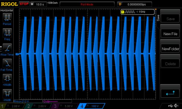 We all know it will blow on the 20th startup, right? wronger than a phone book full of wrong phone numbers |
||||
renewableMark Guru Joined: 09/12/2017 Location: AustraliaPosts: 1678 |
I hadn't replaced the 2110's after the last blow up, it just got tossed across the room ( surprised it still works) But I was replacing them each time something went pop, they are very cheap from China. Something else made it go bang 4 times in a row, but since the nano went on all smooth sailing so I can't explain it, but it has to be something. Each time it was rebuilt I would remove caps and feed it through resistors, check the wave then fit caps, that's when it went bang, but I'm using those caps now, apart from the small one that goes in the middle. I did test that one and it appeared fine. Cheers Caveman Mark Off grid eastern Melb |
||||
| poida Guru Joined: 02/02/2017 Location: AustraliaPosts: 1389 |
Sometimes I think we make the obvious mistake of sacrificing the Brown Chicken, instead of the White Chicken to the God of Good MOSFET Gate Drive. I know, I've made that mistake a few times... After hearing you spent 4 days rebuilding the boards, I'm surprised the board is still not in Earth orbit. We will find a reliable and affordable home brew inverter build system, for all. We will. wronger than a phone book full of wrong phone numbers |
||||
| Solar Mike Guru Joined: 08/02/2015 Location: New ZealandPosts: 1125 |
It might be a good idea to stop using dodgy (aka cheap clones\\copies\\2nds) from China and get quality guaranteed factory items from a reputable dealer, sans RS or similar, may cost more but if it blows, up you know wasn't those chips but something else......possibly; especially in these critical parts of the circuit. |
||||
| renewableMark Guru Joined: 09/12/2017 Location: AustraliaPosts: 1678 |
I was buying them from RS but had similar results, still have 4 in their nice anti electrostatic packs, made no difference. Don't know why the nano control board is different to the 8010 in my case, but it just works. Edit, I blew the machine up 4 times in a row, did no cap tests of sine wave, all fine then added caps and Bam! three times in a row, 4th was fine on start up but went bang on it's second restart. When nano got fitted to Mad power board all has been well, restarted dozens of times, I deliberately tried to make it pop, ran hairdryer and compressor on startup, gave it as much curry as I could, but no issue so far. But also can't explain why the Mad board ran the house trouble free for 6 months, then has issues. Poida has the Mad board running fine at his place, that was the exact one that ran my house totally offgrid for 6 months solid. There has to be something not right with my system somewhere. Johnmc found his solar output was connected too close to his inverter on a bussbar, rather than direct on the battery, that solved his issues overnight. I think I'll pull all the cabling apart, check all lugs/connections, just sit back, take my time and look closely at it all, that was something Mad told me to do 6 months ago, never had the time though, but will have to prioritise it now. Cheers Caveman Mark Off grid eastern Melb |
||||
| johnmc Senior Member Joined: 21/01/2011 Location: AustraliaPosts: 282 |
Mark I also placed a mild steel washer, between the terminals, on the solar output to the battery, so that the inverter to battery has the lest impedance. I done this after (I think it was Solar Mike said, he solved blow up problem on a 10 kw inverter system by adding the small resistance a steel washer on the supply. The above may all be suspect, but I have had no problem since changing the solar supply to the battery. Cheers john johnmc |
||||
| Tinker Guru Joined: 07/11/2007 Location: AustraliaPosts: 1904 |
Interesting idea, that steel washer trick. With my set up I do not think the cabling was ever an issue nor the cause for my inverter failures. The set up looks like this: 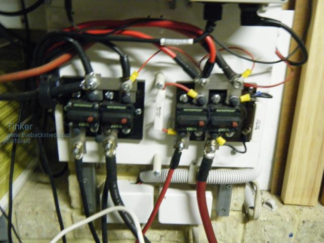 There are C/B in the positive and negative cables. On top are the inputs from two solar controllers (one is a spare, not turned on) and the thick wires go directly to the battery bank. There is a Hall sensor in the negative lead to the battery. On the bottom of the breakers are the outputs to my two inverters, each powering a different area. Yes, I do know these breakers are not rated for the voltage and for that reason are oversized so they do not trip. Their function is to isolate the inverters from the battery so I do not have to disconnect live cables when the inverter gets worked at. I do have dedicated DC breakers in my inverters to handle overloads. All the cables (input & output) are quite short, ~1m max. and fairly beefy. Both inverters still run the EG8010 / IR2110 combination and have the totem pole drivers. Shortly the control boards will be replaced with the nano type. Just to give you another idea as I think it might help if you can look at the many different set ups here and compare them to yours. Klaus |
||||
| tinyt Guru Joined: 12/11/2017 Location: United StatesPosts: 431 |
I looked at my reverse schematic of the oztules control pcb. ON - OFF control section is shown with J9 for the switch connection. If you are using this or something similar: 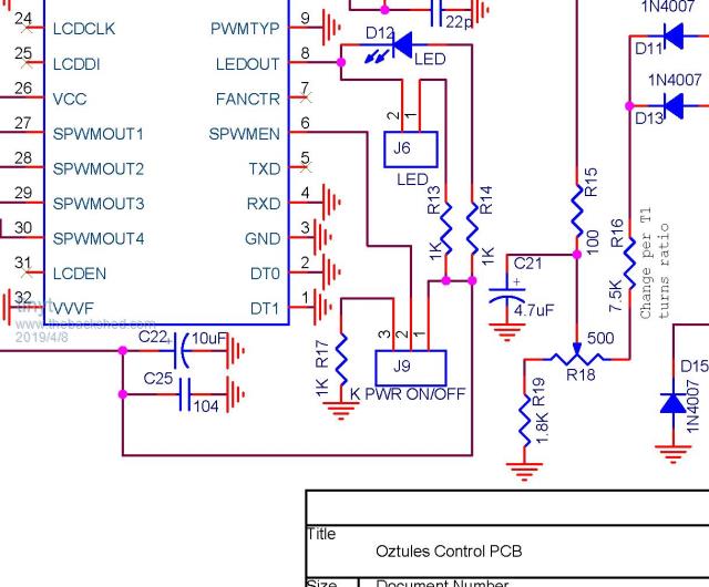 Assuming that an SPDT switch is used and the switch COM is at J9-2 and the other switch terminals are at J9-1 and J9-3 respectively. If the switch is operated, during the short transition time between contacts, switch COM will float to an indeterminate voltage (neither 0 or 5). Maybe this affects the EG8010. Maybe it is better to permanently connect the 1K pull-down resistor to J9-2 and connect an SPST switch between J9-2 and J9-1 to avoid misbehavior of the EG8010. Just my guess. |
||||
| renewableMark Guru Joined: 09/12/2017 Location: AustraliaPosts: 1678 |
Thanks for the input everyone, Tiny the Mad control board is different, and there was an update/fix done to the board to sort out the switch issue. 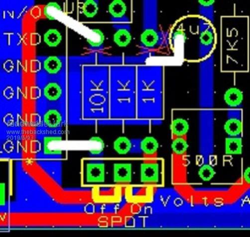 I'll try that mild steel washer, my solar input is connected to a fuse point 30cm from the battery. I thought it was far enough away and close enough to the battery not to cause an issue, but perhaps I'm having the exact problem John did. I'll go direct to battery with the washer. On page 83 I was looking at the pulses that the solar input was causing on the DC supply to the inverter, you can see pulses there. Cheers Caveman Mark Off grid eastern Melb |
||||
| renewableMark Guru Joined: 09/12/2017 Location: AustraliaPosts: 1678 |
Jeeezus, light bulb moment. Those blow up problems coincided with me adding more solar panels to the system. Never even thought about that. Edit, just went and flipped off the breakers to those extra panels, I'll leave them off till the battery wiring is redone. That might have been it, maybe maybe not?? Cheers Caveman Mark Off grid eastern Melb |
||||
| renewableMark Guru Joined: 09/12/2017 Location: AustraliaPosts: 1678 |
Just another update, no problems since all power inputs/outputs have been connected directly to the battery. Looks like even though I was using a very short cable to a buss bar that was enough to cause trouble. Lesson learned, all connections direct to battery. Cheers Caveman Mark Off grid eastern Melb |
||||
Madness Guru Joined: 08/10/2011 Location: AustraliaPosts: 2498 |
I have Negative and Positive Bus Bars made of 30X10X200MM copper with M8 threads, Brass bolts nuts and washers, cables to the battery and inverter are 15mm diameter wire(with insulation over 20MM). There is a small resistance via the 500A Midnite shunt on the negative Bus Bar to the battery. Everything is connected to those 2 Bus Bars, I have never had an issue with this wiring setup. There are only 10 types of people in the world: those who understand binary, and those who don't. |
||||
| johnmc Senior Member Joined: 21/01/2011 Location: AustraliaPosts: 282 |
I have to agree with Mark Until I only connected direct from the battery to the inverter did my unexplained fireworks stop. Interesting note, in the Swiss Studer off grid inverter, installing manual page 19 that the inverter must be connected directely to the battery and all other sources of power or consummers must be connected to the battery so that the battery acts as a buffer. A pdf copy of the studer here I hope I have not mucked up the address . cheers john johnmc |
||||
| johnmc Senior Member Joined: 21/01/2011 Location: AustraliaPosts: 282 |
The address does not work, but if you edit the address and remove https://www.thebackshed.com/forum/ from the front of the address then the pdf file will down load. maybe some one can tell me were I goofed up cheers john  johnmc |
||||
| Warpspeed Guru Joined: 09/08/2007 Location: AustraliaPosts: 4406 |
It all gets to a point where some of you really high power 48v guys might like to start thinking about a 100v system. Cheers, �Tony. |
||||
| renewableMark Guru Joined: 09/12/2017 Location: AustraliaPosts: 1678 |
I think the big difference is you mainly rely on GTI's providing the back charging power. John and myself had big amounts of panels feeding DC to the system. When I got past 8kw of panels hooked up that's when the trouble started. Placing those charge connections directly to the battery solved the problems. Cheers Caveman Mark Off grid eastern Melb |
||||
| Madness Guru Joined: 08/10/2011 Location: AustraliaPosts: 2498 |
Mark I have 1 KW connected via the GTI regulator that I have mentioned to you, another 4.5KW that is coming in via a Midnite MPPT charge controller and a futher 8.5KW of panels connected via 2 GTI's. Most of the battery charging is not done by the GTI's as I have AC loads such as my HWS and AC's that consume a lot of the GTI's output. There are only 10 types of people in the world: those who understand binary, and those who don't. |
||||
| renewableMark Guru Joined: 09/12/2017 Location: AustraliaPosts: 1678 |
Ahh ok, didn't know about the other 4.5kw. Even with 8kw my system was fine, going past that is when the problems started. Probably got a lot to do with the cable size from battery to buss bar, compared to cable size from buss bar to inverter as well. Cheers Caveman Mark Off grid eastern Melb |
||||
