
|
|
Forum Index : Electronics : Bryan's Inverter build
| Author | Message | ||||
Bryan1 Guru Joined: 22/02/2006 Location: AustraliaPosts: 2138 |
Ok I desoldered the 10 pin connector and clearly saw the H02 pin connection didn't have any solder so now the 10 pin connector sit about 5mm high as I soldered the top pads  Now tried again and still voltage to R52 so thought ok the only thing this can be is the ribbon connector Got out my 10 pin ribbon connector for my AVRDude as shown belowH02 L02 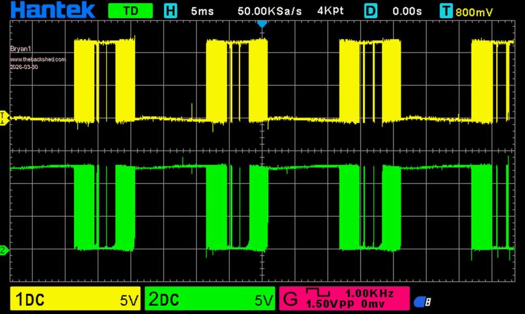 H02 L01 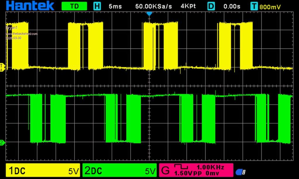 H01 L01 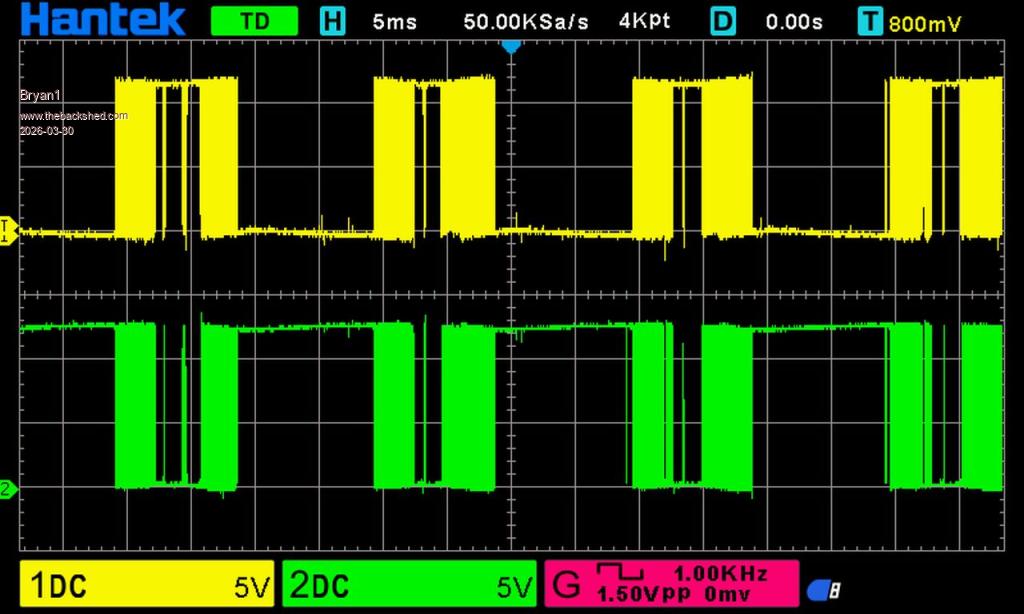 L02 L01 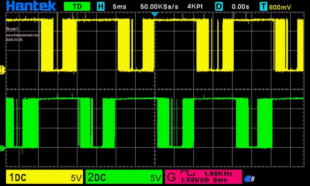 So hopefully these scope pic's are right |
||||
| Bryan1 Guru Joined: 22/02/2006 Location: AustraliaPosts: 2138 |
Now while I had the board running decided to take some voltage checks, the 18V zener was around 18 volts and the TIP25 measured right. Taking voltage reading at the mosfets pads where the positive probe is on Vbat+(26.03 volts) and the negative probe used for the test. L01 G 16.94 D 9.92 S 26.03 H01 G 9.90 D 0 S 9.90 L02 G 17.2 D 10.3 S 26.03 H02 G 10.3 D 0 S 10.3 |
||||
| tinyt Guru Joined: 12/11/2017 Location: United StatesPosts: 561 |
To confuse the enemy?  |
||||
| phil99 Guru Joined: 11/02/2018 Location: AustraliaPosts: 3317 |
So it would seem, converted to ground ref. Vs = 26.03 WRT Gnd WRT + WRT Gnd Vgs L01 L01 Vds G 16.94 9.09 9.09 Vgs D 9.92 16.11 16.11 Vds S 26.03 0 H01 G 9.90 16.13 0 D 0 26.03 9.90 S 9.90 16.13 L02 G 17.2 8.83 8.83 D 10.3 15.73 15.73 S 26.03 0 H02 G 10.3 15.73 0 D 0 26.03 10.3 S 10.3 15.73 |
||||
| Bryan1 Guru Joined: 22/02/2006 Location: AustraliaPosts: 2138 |
Well just sacrificed another 4 mosfets  soldered one on each leg then set it all up turned it on saw the AC voltage rise to 168 volts then a tick tick tick started on the power board which caused the lcd to flicker so that the end of trying to get this inverter to work as I do think the power board is shot. soldered one on each leg then set it all up turned it on saw the AC voltage rise to 168 volts then a tick tick tick started on the power board which caused the lcd to flicker so that the end of trying to get this inverter to work as I do think the power board is shot. |
||||
| Godoh Guru Joined: 26/09/2020 Location: AustraliaPosts: 675 |
Sorry to hear of how much trouble you are having getting the inverter to work Bryan. I hope that Aaron has the other power board going and that that sorts it all out. If all else fails then it may be time to get an aliexpress board and put that in. They seem to work without blowing up. Good luck Pete |
||||
| Bryan1 Guru Joined: 22/02/2006 Location: AustraliaPosts: 2138 |
Yea Pete I am thinking a Ali board may be the go just need to find a good one as on looking at Mikes inverter it is a 48 volt inverter and I'm not going the expense of getting new batteries just to go 48 volts for my shed when this 735AH forklift battery still has alot of life left in it I did find those old 190 panels were having a hard time keeping the battery up so I put 3 off 330 watt panels on the front of my shed so up until after lunch they are putting 30 amps in and for the time in weeks the Victron MPPT was showing the batteries in asborb mode. Now typically when I put those panels up for the first 4 days every morning was cloudy and Murphy was laughing  Regards Bryan |
||||
| Godoh Guru Joined: 26/09/2020 Location: AustraliaPosts: 675 |
aliexpress board 24 volt |
||||
| KeepIS Guru Joined: 13/10/2014 Location: AustraliaPosts: 2196 |
Wiseguys inverter will run from 24 volts to 56 volts, it totally depends on your toroid. The Inverter you built is basically no different to the Ali Inverters. You cannot power up an inverter with a fault with 60000uf of CAPS in circuit - PERIOD! NANO:Inverter V 8.2ks - Linux AvrDude GUI script V4.1 |
||||
| Bryan1 Guru Joined: 22/02/2006 Location: AustraliaPosts: 2138 |
Thanks for that Pete just ordered one now is that the same one as you have mate |
||||
| Godoh Guru Joined: 26/09/2020 Location: AustraliaPosts: 675 |
HI Bryan, the ones I have are 5kw and a 3kw board. There are a couple of manufacturers but they all seem pretty similar. I have been running mine now for around 5 years and not had a blowup yet (leaning on a wooden bench now) I usually ask the seller to supply diagrams, sometimes they come in chinese characters but othertimes they have english instructions. The instructions are pretty basic, but they work out. There are only a few connections to make, but not many. Good luck Pete |
||||
| tinyt Guru Joined: 12/11/2017 Location: United StatesPosts: 561 |
I have made three systems using similar inverter power boards from aliexpress. The ones I bought are reliable unless abused . The HVAC load that abused it has an LRA of 148A or 34kVA. That burned board is the one that I am using now after several band-aid fixes and blow ups. Note that as is, it uses an EGS002 module and you have to modify the EGS002 to avoid blow-ups. I think the modification instructions are also here in this forum. Also, some comes with un-documented SPWM board marked 'CENTURY Inverter SPWM DRIVE' which uses a different asic instead of the EG8010. So, you might have to buy an EGS002 module also. Edited 2026-04-01 23:32 by tinyt |
||||
| Godoh Guru Joined: 26/09/2020 Location: AustraliaPosts: 675 |
I did modify the EGS002 boards as was described by Oztules on this site. Whether the newer boards have been modified i don't know, one would hope that the manufacturers would have sorted the problems by now. As I said I have never blown any of mine up. I have been trying to start a 2.2kilowatt hydraulic pump, my 24 volt 5kw inverter goes out on overload trying to start the pump. But when I spin it up with a pneumatic rattle gun it runs well on the inverter. Bryan if you need the modifications for the EGS002 board I am fairly sure I have them written down somewhere. Good luck Pete |
||||
| Bryan1 Guru Joined: 22/02/2006 Location: AustraliaPosts: 2138 |
I do have a couple of those boards here I bought a while ago so this morning I will have a look and see if they are actually EGS002 boards. So if any mods are needed I can do it to one of the boards I have here so it's already to run to run when the inverter arrives. Edited 2026-04-02 07:15 by Bryan1 |
||||
| Bryan1 Guru Joined: 22/02/2006 Location: AustraliaPosts: 2138 |
Ok just had a look at those EGS boards 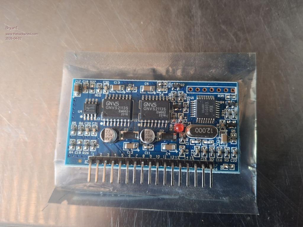 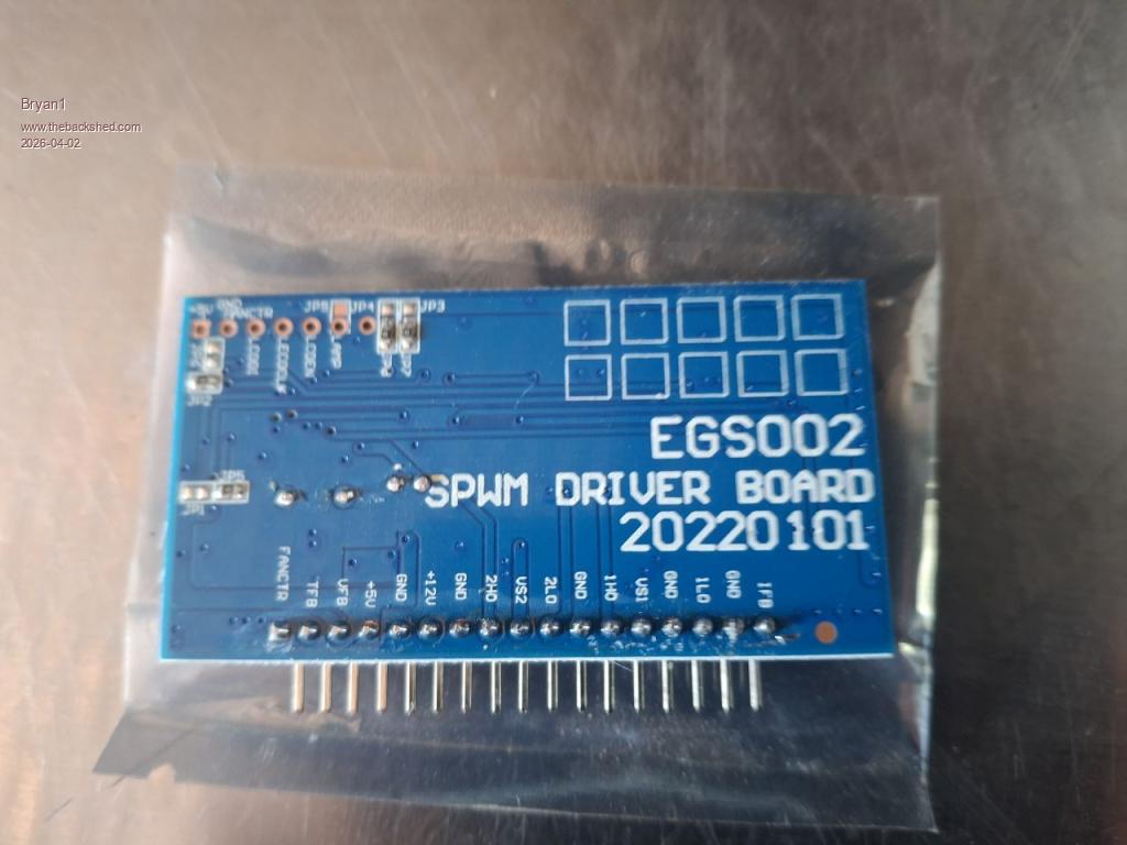 So I do have the EGS002 boards here so what mod's are needed are needed to do this board.I did look at that link TinyT put up and there is a picture of the mod's he did so so is that what I need to do. Now what I found with that inverter build I would put up a post then just go do the change only to find another post said to do more checks so no more making that mistake. |
||||
| Godoh Guru Joined: 26/09/2020 Location: AustraliaPosts: 675 |
Hi Bryan, so to modify the EGS 002 board First remove the IC4 , it is the small chip on the left of the board. Then put a jumper wire to connect the pads where pins 1 and 4 of the chip were. Then short the pads where pins 7 and 8 were. That is all I have done on mine and had no problems. From what I remember the board has some sort of overload mechanism that tends to blow up the mosfets on the main power section if they are mistreated. Getting rid of U4 allows the overload section on the main board to do its job. My abuse by trying to start my wood splitter have only ever resulted in the inverter shutting down, then automatically restarting after about 10 seconds. Good luck Hopefully one day you may find what is wrong with your wiseguy board. cheers pete |
||||
| KeepIS Guru Joined: 13/10/2014 Location: AustraliaPosts: 2196 |
Hi Pete, just to clarify, it's not a wiseguy inverter or board. NANO:Inverter V 8.2ks - Linux AvrDude GUI script V4.1 |
||||
| Godoh Guru Joined: 26/09/2020 Location: AustraliaPosts: 675 |
HI KeepIS, I did think that Bryan started the build a long time ago. I just thought he may have changed to the newer design. Thanks for the clarification Pete |
||||
| Bryan1 Guru Joined: 22/02/2006 Location: AustraliaPosts: 2138 |
Yea Pete that inverter build was a Madboard one that I spent ages to build and it is sad it's now on the scrap pile. Now I pinched this pic from TinyT's thread 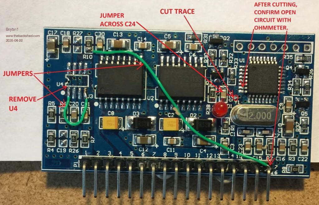 So with his mod yes the U4 chip is removed and pins 1 and 4 had the jumper wire, now the 7-8 pins weren't shorted. Anyway got a couple of weeks before the board arrives so plenty of time to get my head around whats needs to be done. Regards Bryan |
||||
| tinyt Guru Joined: 12/11/2017 Location: United StatesPosts: 561 |
Here is the modification in schematic form. The U4 mod basically disables the SD(shutdown) signal to the IR2110 chips. The trace cut and long jumper changes FANCTR to external SPWM ENABLE (inverter Start/Stop switch), alternate is fixed enable via U4 pin 7 to pin 8 jumper. The C24 jumper disables IFB signal to the EG8010 chip (allows overload abuse). Your choice to incorporate these two mods. .jpg) Edited 2026-04-02 13:17 by tinyt |
||||
| The Back Shed's forum code is written, and hosted, in Australia. | © JAQ Software 2026 |
