
|
|
Forum Index : Electronics : Bryan's Inverter build
| Author | Message | ||||
Bryan1 Guru Joined: 22/02/2006 Location: AustraliaPosts: 2155 |
Ok went and had some lunch and while going to the shops for some grub came up the idea of just using some circuit breakers so each inverter can be run without back feeding.  So with the shed feed AC wires they went into the top of the circuit breakers where one wire was common on the output and with the other wire I used 2 circuit breakers so to complete the AC only one switch is turned on So now back running on the Kipoint until I get this heat problem sorted on L02. Now thinking about that 2 of the drain PCB pads didn't accept solder so when removing the mosfets before could of taken the pcb pad when I unsoldered them. So to get a good contact for the drain pin which goes to the top layer I could scratch the silk screen to reveal fresh copper then solder the drain to that. All this could done with the inverter in place as it is the 2 outer mosfets so what do you guy's think of this hair brained idea ? Regards Bryan |
||||
| Bryan1 Guru Joined: 22/02/2006 Location: AustraliaPosts: 2155 |
Ok I found a fan with a connector and it sat nicely on the VS2 side so just used a bit of duct tape to hold the fan in place for testing. Now the heatsink was on 44C so when the inverter booted up that fan turned on straight away and it took about 5 minutes to get it down under 30C. Now while typing this message I went and had a look at the HS temp where I saw it turn on at 36C and about a minute later it was back to 35C and now down to 32C.So this fan can stay on as it's doing to job I did block 3 of side vents with duct tape so when the Toroid fan goes on the air escape is on the top left above the TIP25 heatsink.Tonight I will switch back to the Kipoint for overnight and tomorrow some real testing can be done. Anyway as the energy meter is working when the fridge isn't on the average draw is under 200 watts which includes all my shed lights this computer and my shed boombox. I did turn on all my machine VFD's and with all three going only about 600 watts Regards Bryan Edited 2026-04-09 17:01 by Bryan1 |
||||
| Bryan1 Guru Joined: 22/02/2006 Location: AustraliaPosts: 2155 |
As I saw it cycling nicely decided to leave the inverter going overnight and when I turned everything off the energy meter was showing 4-5 watts on standby , the only current draw will be my shed fridge. Now checked the current draw using my clamp meter where 3-4 amps was shown.So tomorrow time to test my mig welder and see if it works then the fun can really start. |
||||
Revlac Guru Joined: 31/12/2016 Location: AustraliaPosts: 1285 |
hat seems to be too much heat at idle, it should be just on ambient temp when there is no load on the inverter, and current would be just less than 1Amp (with no load on the 230vac output) going by the numbers on the previous page. Be good to check the rating on the welder, the one I have requires 10Kva when flat out (think it was that or another welder?), even when only light welding the initial arc puts a surge on the inverter as it tries to fill the capacitor bank in the welder. I was welding with the Mad inverter yesterday and have no fan on it at all, and heatsink temp is barely noticeable over the ambient temp Cheers Aaron Off The Grid |
||||
| Bryan1 Guru Joined: 22/02/2006 Location: AustraliaPosts: 2155 |
Aaron it was only the L02 heatsink that was getting warm and by setting the fan turn on for 35C with that fan duct taped on the temp doesn't go over 36C and it soon drops back to 29C. Watching it today the fan would cycle about 5 times an hour where it took less than 5 minutes to get back down to 29C. Now it was showing on the energy meter around 0.5 amps on standby so I will see in the morning how the inverter went. Now with my Unimig viper 182 they do say 7Kva on the plate so it will be interesting to see how it goes. |
||||
| tinyt Guru Joined: 12/11/2017 Location: United StatesPosts: 561 |
Maybe, that mosfet is bad or it is the only one working properly for the L02 group. You can try removing it and re-test with the same load and see if the temperature has spread evenly among the remaining L02 mosfets. If so, solder in a new mosfet and re-test. Edited 2026-04-09 23:02 by tinyt |
||||
| Bryan1 Guru Joined: 22/02/2006 Location: AustraliaPosts: 2155 |
Ok new morning for testing Saw the HS was sitting on 29C and the TOR 23 so turned on the shed for a average 200-300 watt current draw. Now I have a single and dual old heating elements so decided to use those for the fist load test. 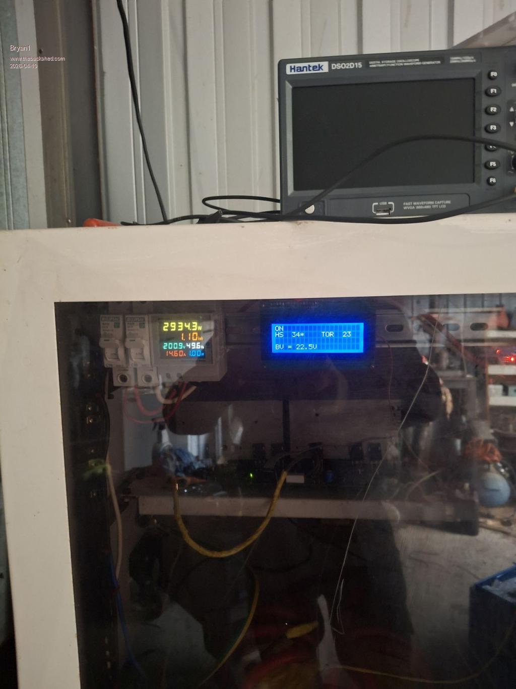 So 3Kw so far  Now the HS and TOR have around 6 to 11 C difference and watching this morning the HS came on after 25 minutes and ran for 4 minutes, so I do think it's best to leave it and see how it goes. |
||||
| Bryan1 Guru Joined: 22/02/2006 Location: AustraliaPosts: 2155 |
Ok ran the test again and saw 3.4Kw load then it dropped to 3Kw so thought best to know what the DC current is at 3Kw 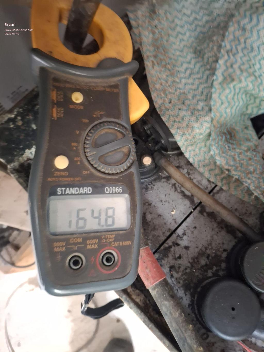 |
||||
| Godoh Guru Joined: 26/09/2020 Location: AustraliaPosts: 678 |
Hi Bryan, sounds like the inverter is working, the current at 3kw load seems a bit high. That would mean the inverter is only running at 76% efficiency. Are you sure that there aren't other loads on? As your loads are resistive I would not expect the inverter to be pulling 3900 watts to run a 3000 watt load. Pete |
||||
| Bryan1 Guru Joined: 22/02/2006 Location: AustraliaPosts: 2155 |
Hi Pete the single element is 1.5Kw and the dual element is 2.4Kw so yea of the element ratings it is 3.9Kw Also I do have the shed power load going so with the shed fridge going that may count for 300 watts. Now I do have an electric 1800 watt oven here so decided to put all 3 elements on 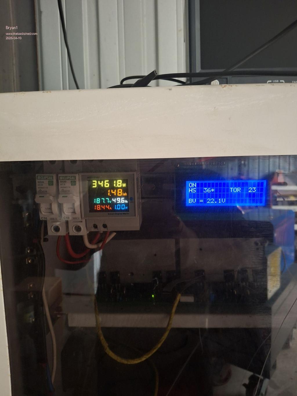 The DC current draw 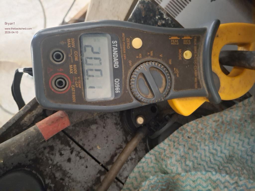 |
||||
| Godoh Guru Joined: 26/09/2020 Location: AustraliaPosts: 678 |
Ok that sounds better. Pretty impressive that it is running that sort of load now. Is the small screen on the right showing temperature, if so that is also pretty good. Good luck with the welder etc. I can weld with my 180 amp mig but my inverter goes out on overload if I wind the current up too much. Still it does what I want, Nice to see it up and running now Pete |
||||
| Bryan1 Guru Joined: 22/02/2006 Location: AustraliaPosts: 2155 |
Yes Pete the LCD shows the temps and with the HS temp it will rise to 36C then the fan turns on and cools it down to 29C then the cycle repeats. The L02 heatsink is the only one warming up but these load tests do prove the inverter can handle the big currents so although there is a problem I'm going to see how it goes long term as it just works |
||||
| tinyt Guru Joined: 12/11/2017 Location: United StatesPosts: 561 |
Observations: BV = 22.1 volts (from picoverter) DC current = 200.1 Amperes (clamp meter) Inverter Input Power draw = 22.1 x 200.1 = 4422.2 VA or Watts AC load = 3461.8 Watts (from Multi-Function meter, pF = 1) Difference = 4422.2 - 3461.8 = 960 Watts. Edited 2026-04-10 13:21 by tinyt |
||||
| KeepIS Guru Joined: 13/10/2014 Location: AustraliaPosts: 2199 |
For a start, how about making the Inverter regulate correctly, all efficiency readings should be ignored until then. NANO:Inverter V 8.2ks - Linux AvrDude GUI script V4.1 |
||||
| Bryan1 Guru Joined: 22/02/2006 Location: AustraliaPosts: 2155 |
Keepis I left this inverter running overnight where that multi function unit said 4-5 watt and it was still the same this morning. Over night when the fridge run didn't make a huge difference in the over night low of the batteries. In fact it was good 1/2 a volt higher using the app for the Victron MPPT than the last few days and yes I do use SG as a reading of battery charge. Now I just took some temp readings with my infrared temp gauge where the mosfets on L01 are about 2C lower than L02, now looking at the 32C I saw on the mosfets on the outer mosfets the inner mosfet that used for the test is the same as the L01 mosfets. I am thinking of making the lower temp cut off for HS to 33C as from several temp tests do confirm that 32-33C reading. 4.4Kw so far is a good sign I think too and seeing 18.5 amps on the AC side does make me want to see 20 amps Also while doing these test I see the AC voltage drop under the load now the 49.6Hz shown on the multi function used didn't budge under load so I do think that is a good sign this inverter is working correctly. Edited 2026-04-10 14:00 by Bryan1 |
||||
| KeepIS Guru Joined: 13/10/2014 Location: AustraliaPosts: 2199 |
The Nano frequency will not shift with load or regulation, the AC on that Mains monitor should not drop more than a volt or two, depending on the quality of the PF factor calculations for a given load with AC monitor quality. The picture showed 187v on the AC meter @ 3.4kW, that is a nothing load, AC should not drop unless, wiring, toroid or VFB regulation are not working correctly. Or - due to toroid design or very low DC input, causing close to 99% PWM drive at low power, leaving no headroom for higher load current regulation. Or the photo is wrong? . Edited 2026-04-10 14:37 by KeepIS NANO:Inverter V 8.2ks - Linux AvrDude GUI script V4.1 |
||||
| Godoh Guru Joined: 26/09/2020 Location: AustraliaPosts: 678 |
Nicely spotted KeepIS. I didn't look at the energy meter and see how low the voltage had dropped that low. That is definitely something that needs addressing. Pete |
||||
| Bryan1 Guru Joined: 22/02/2006 Location: AustraliaPosts: 2155 |
Keepis I bought that energy meter on ebay and off memory it was about $60, now I used my DMM to measure the AC voltage and it was 0.5 volts lower than the energy meter with a 200 watt current draw. as the fridge was running. When I do the next test tomorrow I will use my DMM for the AC measurement and yes if the voltage does vary it may be time to unsolder the VS and battery heavy wires and make up a new power board as I do have a couple of them here. |
||||
| Bryan1 Guru Joined: 22/02/2006 Location: AustraliaPosts: 2155 |
Ok just had to try another test With the single element 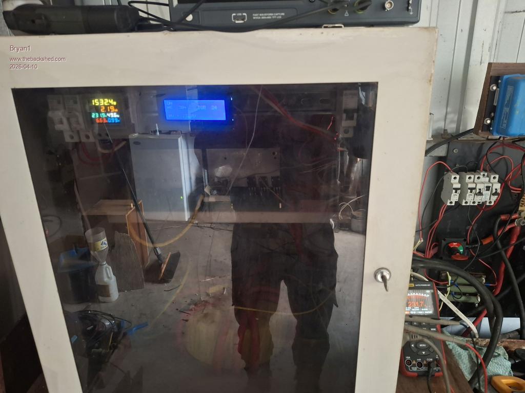 Now with the single element and the toaster oven 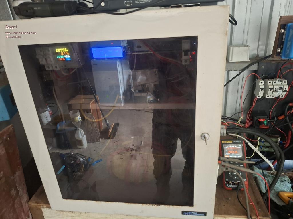 So at 1.5Kw no voltage drop but at 2.8Kw the voltage drops so yes a new problem to try and solve. Now the toroid temp hasn't risen and is at ambient temp so I think that is a good sign That ching inverter board will be here next week so I can do the mod's for that and test it while I'm waiting for new parts to arrive for making the new power board. Until then I will leave this inverter going and I have set the Kipoint to fall back on if needed. Edited 2026-04-10 16:03 by Bryan1 |
||||
| KeepIS Guru Joined: 13/10/2014 Location: AustraliaPosts: 2199 |
Those energy meters are quite accurate, I've used many of these over the years and currently have 3 in the Inverter switchboard panel, all are within 500mV of each other. Try testing with purely resistive loads when comparing them against a True RMS DVM. EDIT: I wrote this while you were posting your photos above, so you have now confirmed the accuracy of the Meter and the problem you have. . Edited 2026-04-10 16:10 by KeepIS NANO:Inverter V 8.2ks - Linux AvrDude GUI script V4.1 |
||||
| The Back Shed's forum code is written, and hosted, in Australia. | © JAQ Software 2026 |
