
|
|
Forum Index : Microcontroller and PC projects : PIO explained PICOMITE
| Author | Message | ||||
| Volhout Guru Joined: 05/03/2018 Location: NetherlandsPosts: 5923 |
chapter 4 - new: WRAP and WRAP TARGET enhanced JMP The state machines in the PIO are especially usefull when they can repeat tasks (independent of the ARM). As we have seen in previous examples, there is always an uncoditional JMP at the end of the PIO program. This JMP is the reason that the code repeats. But the PIO designers envisioned that every single program running in a PIO would have such a JMP and saw the disadvantage of that JMP. 1/ It eats up 1 instrcution cycle (delay) 2/ It eats up 1 program memory location That is where the state machine WRAP and WRAP TARGET are important. WRAP TARGET: this label is placed at the location where the JMP ends up. WRAP: this label is placed after the instruction of the PIO program, where the JMP would start. Using WRAP is a configuration of the state machine. It is not in the program. Below example shows how it works. Note that using WRAP and WRAP TARGET is immediate (no delay) and is no program instruction. This piece of code is the 2 tone siren (thanks to phil99). 'line code comment ' 0 Ā E081 SET GP0 output '.wrap target ' 1 Ā E001 Ā Ā ĀSET gp0 high ' 2 Ā 00C5 Ā Ā ĀJMP (GP2=1) to 5, (skip instructions 3 & 4) ' 3 Ā E001 Ā Ā ĀSET gp0 high ' 4 Ā E000 Ā Ā ĀSET gp0 low ' 5 Ā E000 Ā Ā ĀSET gp0 low '.wrap ' 6 Ā 0001 Ā Ā ĀJMP 0001 The WRAP label is placed to avoid the original JMP. The WRAP TARGET is placed before line 1. When this WRAP configuration is added, the state machine executes follwing sequence: 0,1,2,3,4,5, 1,2,3,4,5, 1,2 etc... The JMP instruction can be removed, it is not used anymore. So WRAP = 5, WRAP TARGET = 1 (from line 5 go to line 1) The WRAP=5 and WRAP TARGET=1 values are programmed in the EXECCTRL configuration (see chapter 3). EXECCTRL a,b,c a/ the pin number where conditional JMP looks at (GP2 in our program) b/ WRAP TARGET address (1 in above example) c/ WRAP address (5 in above example). This leads to following program for the 2 tone siren, using WRAP. Note: because the JMP instrcution is gone, a 1 cycle delay is added to line 5. 'disconnect ARM from GP0. - 1000Hz / 1500Hz Square Wave SetPin gp0,pio1 'configure pio1 p=Pio(pinctrl 0,1,,,,gp0,) e=Pio(execctrl 2,1,5) <-------we filled wrap and wrap target in here f=1000 * 6 'Hz 'line code comment ' 0 Ā E081 SET GP0 output '.wrap target ' 1 Ā E001 Ā Ā ĀSET gp0 high ' 2 Ā 00C5 Ā Ā ĀJMP (GP2=1) to 5, (skip instructions 3 & 4) ' 3 Ā E001 Ā Ā ĀSET gp0 high ' 4 Ā E000 Ā Ā ĀSET gp0 low ' 5 Ā E000 Ā Ā ĀSET gp0 low, dly=1 '.wrap 'program pio1 PIO program line 1,0,&hE081 PIO program line 1,1,&hE001 PIO program line 1,2,&h00C5 PIO program line 1,3,&hE001 PIO program line 1,4,&hE000 PIO program line 1,5,&hE100 'start the pio1 code PIO start 1,0 'toggle GP2 in MMBasic SetPin gp2,dout SetPin gp8,fin Do ĀPin(gp2) = Not Pin(gp2) 'toggle pin GP2 Ā'Print Pin(gp8) ĀPause 2000 Loop End - new: PIO PROGRAM versus PIO PROGRAM LINE In our previous examples we have programmed the PIO line by line. I find that illustrating and educating. But in some cases the PIO program is a small basic block in a larger MMBasic program. It may be desirable to have a more compact method to program the PIO. That is why PROGRAM PIO exists. This is a command that programs the complete 32 word program memory from an integer array. For our short programs that is not a big gain, but once you have to program 32 words, the code is much more compact. You have to dimension an integer array (64 bit values), and fill that array with the 16 bit program instructions (4 instructions per array cell). Your array must be 32/4=8 wide (or 0...7). These 4 instructions map as follows: 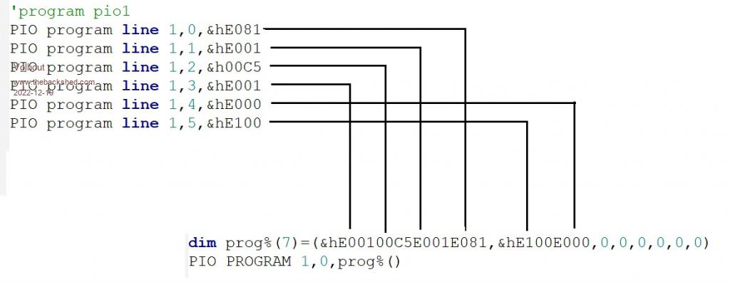 Programming the PIO, using this alternative method would look like this: 'disconnect ARM from GP0. - 1000Hz / 1500Hz Square Wave SetPin gp0,pio1 'configure pio1 p=Pio(pinctrl 0,1,,,,gp0,) e=Pio(execctrl 2,1,5) f=1000 * 6 'Hz 'line code comment ' 0 Ā E081 SET GP0 output '.wrap target ' 1 Ā E001 Ā Ā ĀSET gp0 high ' 2 Ā 00C5 Ā Ā ĀJMP (GP2=1) to 5, (skip instructions 3 & 4) ' 3 Ā E001 Ā Ā ĀSET gp0 high ' 4 Ā E000 Ā Ā ĀSET gp0 low ' 5 Ā E000 Ā Ā ĀSET gp0 low, dly=1 '.wrap dim prog%(7)=(&hE00100C5E001E081,&hE100E000,0,0,0,0,0,0) PIO PROGRAM 1,prog%() 'write the configuration (note we added "e") PIO init machine 1,0,f,p,e,,0 'start the pio1 code PIO start 1,0 'toggle GP2 in MMBasic SetPin gp2,dout SetPin gp8,fin Do ĀPin(gp2) = Not Pin(gp2) 'toggle pin GP2 Ā'Print Pin(gp8) ĀPause 2000 Loop End Or, very compact, without any comments, for the 5kbyte programming challenge dim prog%(7)=(&hE00100C5E001E081,&hE100E000,0,0,0,0,0,0):PIO PROGRAM 1,prog%() PIO init machine 1,0,6000,Pio(pinctrl 0,1,,,,gp0,),Pio(execctrl 2,1,5),,0 PIO start 1,0 - new exercise The exercise this chapter, is combining all the knowlege we have acquired so far in a real challenge: Using 5 outputs GP0 to GP4 create a night rider scanner (LED LIGHT traveling back and forth) that can be switched ON and OFF from MMBasic from the keyboard. Aim for 2 scans per second. Edited 2022-12-19 21:51 by Volhout PicomiteVGA PETSCII ROBOTS |
||||
| Mixtel90 Guru Joined: 05/10/2019 Location: United KingdomPosts: 8899 |
Can anyone tell me what the default font/size is for the manual? Mick Zilog Inside! nascom.info for Nascom & Gemini Preliminary MMBasic docs & my PCB designs |
||||
| Volhout Guru Joined: 05/03/2018 Location: NetherlandsPosts: 5923 |
Yes, please... I am honoured by your offer.... I'll put in some extra effort to make this a success... Volhout PicomiteVGA PETSCII ROBOTS |
||||
| phil99 Guru Joined: 11/02/2018 Location: AustraliaPosts: 3288 |
One solution, though I am sure there are less clumsy ways of doing it. > ? MM.INFO(CPUSPEED) 48000000 > LIST ' - Ch 4, 5 LED scanner 2.86 Hz 'disconnect ARM from GP0 to GP4. SetPin gp0,pio1 SetPin gp1,pio1 SetPin gp2,pio1 SetPin gp3,pio1 SetPin gp4,pio1 'configure pio1 p=Pio(pinctrl 0,5,,,,gp0,) e=Pio(execctrl 0,1,8) f=732 Ā'Hz - AS LOW AS IT WILL GO WITH OPTION CPUSPEED 48000 'line code Ā comment ' 0 Ā E09F Ā SET GP0 - GP4 output ' 1 Ā FF01 Ā SET gp0 high, others low, delay 31 ' 2 Ā FF02 Ā SET gp1 high, others low, delay 31 ' 3 Ā FF04 Ā SET gp2 high, others low, delay 31 ' 4 Ā FF08 Ā SET gp3 high, others low, delay 31 ' 5 Ā FF16 Ā SET gp4 high, others low, delay 31 ' 6 Ā FF08 Ā SET gp3 high, others low, delay 31 ' 7 Ā FF04 Ā SET gp2 high, others low, delay 31 ' 8 Ā FF02 Ā SET gp1 high, others low, delay 31 ' Wrap to line 1 'program pio1 Dim a%(7) = (&hFF04FF02FF01E09F,&hFF04FF08FF10FF08,&hFF02,0,0,0,0,0) PIO program 1,a%() 'write the configuration (note we added "e") PIO init machine 1,0,f,p,e,,0 'start the pio1 code PIO start 1,0 SetPin gp8,fin Do Pause 2000 Print Pin(GP8) Loop End > pio stop 1,0 > pio start 1,0 > ' Or >PIO EXECUTE 1,0,&hE080 Ā' switch all pins off >PIO EXECUTE 1,0,&hE09F Ā' switch all pins on Edited 2022-12-20 17:22 by phil99 |
||||
| Volhout Guru Joined: 05/03/2018 Location: NetherlandsPosts: 5923 |
@phil99, Great solution !! That is what I like about this. Of coarse I had my own idea's how I would do it ready, but you have found new ways. I did not consider changing the CPUSPEED lower that 126MHz. But you can !! And offering 2 ways to start-stop the leds 1/ PIO start and PIO stop 2/ PIO EXECUTE a command that switched the pins to input (LED off) and to output (LED ON) while the PIO is running. I am enjoying this very much. Thank you !!! Volhout My solution would use the same PIO SET commands, but interleave them with WAIT's for GPx, each having delay 31. So the program would be double the size. In the next chapter we will learn how to use the X and Y registers to achieve (amongst other) longer delays.... PicomiteVGA PETSCII ROBOTS |
||||
| Volhout Guru Joined: 05/03/2018 Location: NetherlandsPosts: 5923 |
The previous exercise was perfectly demonstrated by phil99, who used all tricks we learned so far, and one more.... One other solution could have been (using many more program cells): ' 5 LED scanner 'disconnect ARM from GP0 to GP4. SetPin gp0,pio1 SetPin gp1,pio1 SetPin gp2,pio1 SetPin gp3,pio1 SetPin gp4,pio1 setpin gp5,dout 'PIO will read but MMBasic will set this pin 'configure pio1 p=Pio(pinctrl 0,5,,,,gp0,) Ā'5 pins SET starting GP0 e=Pio(execctrl 0,1,18) Ā Ā Ā'wrap=18, wrap target = 1 f=2000 Ā'Hz 'program pio1 pio program line 1,0,&hE09F 'set GP0..GP4 output '.wrap target PIO program line 1,1,&hFF01 'set gp0 high, dly=31 PIO program line 1,2,&h3F85 'wait for GP5 to be high, dly=31 PIO program line 1,3,&hFF02 'set gp1 high, dly=31 PIO program line 1,4,&h3F85 'wait for GP5 to be high, dly=31 PIO program line 1,5,&hFF04 'set gp2 high, dly=31 PIO program line 1,6,&h3F85 'wait for GP5 to be high, dly=31 PIO program line 1,7,&hFF08 'set gp3 high, dly=31 PIO program line 1,8,&h3F85 'wait for GP5 to be high, dly=31 PIO program line 1,9,&hFF10 'set gp4 high, dly=31 PIO program line 1,10,&h3F85 'wait for GP5 to be high, dly=31 PIO program line 1,11,&hFF08 'set gp3 high, dly=31 PIO program line 1,12,&h3F85 'wait for GP5 to be high, dly=31 PIO program line 1,13,&hFF04 'set gp2 high, dly=31 PIO program line 1,14,&h3F85 'wait for GP5 to be high, dly=31 PIO program line 1,15,&hFF02 'set gp1 high, dly=31 PIO program line 1,16,&h3F85 'wait for GP5 to be high, dly=31 PIO program line 1,17,&hFF01 'set gp0 high, dly=31 PIO program line 1,18,&h3F85 'wait for GP5 to be high, dly=31 '.wrap 'write the configuration PIO init machine 1,0,f,p,e,,0 'start the pio1 code PIO start 1,0 'control leds "1"=ON, "0"=OFF, "x"=exit do Āa$=inkey$ Āif a$="1" then pin(gp5)=1 Āif a$="0" then pin(gp5)=0 Āpause 20 loop until a$="x" pio stop 1,0 End chapter 5 : the X and Y registers The PIO state machines have 2 registers, 32bit wide, that can be used for counting. These are called X and Y (probably in heritage of the 6502 ?). The registers can be used to COUNT DOWN only. So not count up, only count down. If you really have to count up, you count down, and then invert the end result. So you can do things like (pseudo code) set pin output .wrap target set X=31 label1: set pin high decrement X and jump (X<>0) to label 1 set X=31 label2: set pin high decrement X and jump (X<>0) to label 2 set pin low .wrap The SET instruction to set a value of 31 to register X is one of the few instructions to fill X (and Y) with a value. So the use of X and Y is pretty limitted until we discuss the ISR and OSR registers (next chapter). 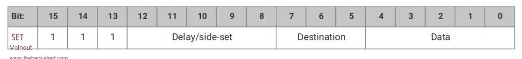 DELAY: discussed before DESTINATION: "001" set X value ("010" set Y value) DATA: the binary data to set X (or Y) to. Only 5 LSB bits, the other bits (31...5) are set to 0 SET X=31, dly=0 translates to 111 00000 001 11111 = 1110 0000 0011 1111 = &hE03F The decrement and jump instruction is a conditional JMP, the JMP instruction we have used before. But it can take X or Y as a condition and POST DECREMENT the X or Y register. So first it checks if X (or Y) equals zero. If not, it decrements the value, and makes the jump When X equals zero, the next instruction is executed.  DELAY: discussed before , let's set it to 31 CONDITION: "010" jump when X<>0, decrement X. "100" does the same for the Y register. ADDRESS: where to jump to JMP (X<>0) X-- ADDRESS, dly=31 translates to 000 11111 010 ADRES = 0001 1111 0100 address = &h1F4x So our program will become line code comment 0 Ā Ā ĀE081 set GP0 output .wrap target 1 E03F set X=31 2 E001 set GP0 high 3 1F42 JMP (X<>0) X-- 2, dly=31 4 E03F set X=31 5 E000 set GP0 low 6 1F45 JMP (X<>0) X-- 5, dly=31 .wrap The 2-3 loop and the 5-6 loop rotate 31 times, decrementing X to zero. Each loop has 2 instructions and 31 additional delays. So each loop takes 33x31 cycles, or roughly 1000. With a 2kHz state machine clock we would blink the LED at GP0 with roughly 1 Hz. Above program requires a pincontrol to use GP0, and execute control with wrap=6, wrap target =1 ' using X in a count down 'disconnect ARM from GP0. SetPin gp0,pio1 'configure pio1 p=Pio(pinctrl 0,1,,,,gp0,) Ā'1 pin SET starting GP0 e=Pio(execctrl 0,1,6) Ā Ā Ā 'wrap=6, wrap target = 1 f=2000 Ā'Hz 'program pio1 pio program line 1,0,&hE081 'set GP0 output '.wrap target PIO program line 1,1,&hE03F 'set X=31 PIO program line 1,2,&hE001 'set GP0 high PIO program line 1,3,&h1F42 'JMP (X<>0) X-- 2, dly=31 PIO program line 1,4,&hE03F 'set X=31 PIO program line 1,5,&hE000 'set GP0 low PIO program line 1,6,&h1F45 'JMP (X<>0) X-- 5, dly=31 '.wrap 'write the configuration PIO init machine 1,0,f,p,e,,0 'start the pio1 code PIO start 1,0 End This chapter is the last chapter where we will be blinking LED's. Next chapter will discuss the use of the FIFO, and then things get exciting. So buckle up..... The exercise this chapter is: adapt above program to do the same using the Y register. Edited 2022-12-22 07:32 by Volhout PicomiteVGA PETSCII ROBOTS |
||||
| phil99 Guru Joined: 11/02/2018 Location: AustraliaPosts: 3288 |
' using Y in a count down 'disconnect ARM from GP0. SetPin gp0,pio1 'configure pio1 p=Pio(pinctrl 0,1,,,,gp0,) Ā'1 pin SET starting GP0 e=Pio(execctrl 0,1,6) Ā Ā Ā 'wrap=6, wrap target = 1 f=2000 Ā'Hz 'program pio1 PIO program line 1,0,&hE081 'set GP0 output '.wrap target PIO program line 1,1,&hE05F 'set Y=31 PIO program line 1,2,&hE001 'set GP0 high PIO program line 1,3,&h1F82 'JMP (Y<>0) Y-- 2, dly=31 PIO program line 1,4,&hE05F 'set Y=31 PIO program line 1,5,&hE000 'set GP0 low PIO program line 1,6,&h1F85 'JMP (Y<>0) Y-- 5, dly=31 '.wrap 'write the configuration PIO init machine 1,0,f,p,e,,0 'start the pio1 code PIO start 1,0 SetPin gp6,fin,10000 Do ĀPause 10000 ĀPrint Pin(GP6) Loop End Edited 2022-12-22 09:31 by phil99 |
||||
| Volhout Guru Joined: 05/03/2018 Location: NetherlandsPosts: 5923 |
Hi Phil99, That is a quick response. Looks like you solved this between breakfast and lunch... This is correct. The exercise was simple. And correctly solved. Up to now we have been playing with things that could simply be resolved in MMBasic also. Blinking LED's, sound in a buzzer, reading a GP input pin state. The next chapter will form the basis for a real project: a multifunction counter. So a real measurement device that can accurately measure puls width, period, frequency up to 40MHz. A practical device will consist of - hardware: input circuit, so we can als measure signal that are not 3.3V logic - hardware: and LCD (or LED) display that shows the measured result - hardware: push buttons to select the range and function - PIO code: the heart of the insrument doing the fast sampling - MMBasic program: the user interface and math (PIO cannot do math). In this course we will design the PIO code. Once we have the PIO code, community members can step in to design a board, write a nice user interface, or design a nice input circuit. Next chapter we will design the pulse width measurement core in PIO. Volhout PicomiteVGA PETSCII ROBOTS |
||||
| Volhout Guru Joined: 05/03/2018 Location: NetherlandsPosts: 5923 |
Chapter 6 : FIFO and ISR The PIO state machines have been used for stand alone manipulation of PIO pins up to now. But the power of PIO in combination with the ARM inside the RP2040 is where the real strength is. For that purpose there is a "gateway" between the PIO and the ARM processor : the FIFO's. The ARM processor can read 32 bit data from the PIO through a read FIFO, and can write 32 bit data through a write FIFO. In this chapter we will focus on the read FIFO. The FIFO is 4 words deep. So it will fit 4 32bit words. Each state machine has it's own FIFO's. In MMBasic you can read the FIFO with the PIO READ command PIO READ a,b,c,d a/ the PIO number b/ the state machine number c/ the number of words to read d/ the destination of the data. Must be an integer, can be a variable, or an array when multiple words are read. So reading 2 words from state machine 3 in PIO 1 would be: DIM values%(1) PIO READ 1,3,2,values%() Before MMBasic can read usefull data from the FIFO state machine, the PIO state machine must first write data into the FIFO. And there is only 1 possible way to do that: PUSH. The PUSH instruction can put data from the state machine into the FIFO. But it can push only 1 register: the ISR register. There are no provisions in the PIO too PUSH the X register, or the Y register, or pin states. Only the ISR register can be pushed into the FIFO. We will detail the ISR register later, let's first focus on the PUSH instrcution itself.  DELAY/SIDE SET : we have discussed delay before IFF: If Full (we will not detail this here) BLK: Blocking Blocking: this is like the WAIT instruction. In case the FIFO is full, stop the state machine until it can push data into the fifo. When block is used, no data get's lost. But the state machine stops. In some cases that is desirable, sometimes it is better to leave the state machine working, and discard the data that does not fit in the FIFO. It depends on the speed of the ARM processor if blocking occurs. Since the PIO can run much faster than MMBasic can execute, this must be carefully considered. The ISR The ISR register (Input Shift Register) is designed to gather data from the PIO, like shift data in read from PIO pins. Like SPI, you give X clocks, and read the SPI register to see what Āhas come in on the MISO pin. But the PIO is more flexible, it can also shift in multiple bits at a time (i.e. 8 bits, 32bits). But you need a PIO program to do that. Using the ISR to shift IN data is something for future chapter. For now we will use the ISR register to get data from the PIO to the ARM. We have seen in previos chapter that the X register can be used as a counter. Lets count things, and tell MMBasic what we counted. The data would go like this X -----> ISR -----> FIFO ------> MMBasic Above we have explained how to get data from the FIFO in MMBasic The PUSH instruction forces the ISR value into the FIFO But how do we get the X value into the ISR: the MOV instruction 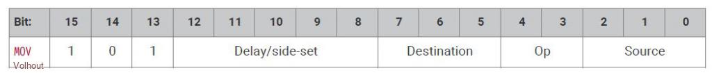 The MOV instruction is used to copy data from one register to another. It can be used to copy data from SOURCE (i.e. X) to DESTINATION (i.e. ISR), and on the way doing this also do some basic manipulation (like invert the data). DELAY/SIDE SET : discussed before DESTINATION: "110" for ISR OP(eration): "00"=none, "01"=invert,"10"=bit reversed SOURCE: "001" for X, "010" for Y, "011" for NULL (&h0) Read chapter 3.4.8 on the RP2040 manual for all the options. For now we have all the block to have MMBasic read data from the PIO state machines. Let's get started on our big project: the multifunction counter. Multifunction counter. A multifunction counter is a test instrument that can be used to measure frequencies, pulse width, count events. The picomite already has the basic functionality to do this build in through the MMBasic SETPIN GPx,FIN or CIN commands. Inside MMbasic these functions are software functions with limitted bandwidth (500kHz). The PIO can outperform MMBasic because it is so fast. To create a multifunction counter we will have to do some system engineering first. What should the multifunction counter have: 1/ A input for logic signal 2/ A AC input for analog signals (needs amplifier, to measure crystal oscillators or so) 3/ B input for logic signal (think of START = A, STOP = B, or frequency ratio A/B) 4/ Diagnostics indicators (like a "GATE" LED). Gate OUT logic signal is also a nice feature 5/ human interface (buttons/display) To keep this compatible with the VGA picomite, it is best if we limit to the GP0...GP5 IO pins for the PIO. First we determine that the A pinput will be GP0, and the B input will be GP1. The PIO can sample these pins, in fact each state machine can. So we can have multiple statemachines looking at the same pin, at the same time. So below is possible: GP0 - tested by state machine 1 to determine pulse width high - tested by state machine 2 to determine pulse width low - tested by state machine 3 to measure frequency - drive by MMbasic PWM as a test signal. Lets determine GP2 is the GATE output to drive an LED, or a GATE output signal. That leaves GP3,4,5 for future enhancements. The beauty of PIO in MMBasic is that we can re-program the PIO when the multifunction counter changes the test function. So we get a very versatile instrument, that we can expand by software update. The first function we will focus on is measuring pulse width. pseudo code set X=0 wait pin=1 label: inc X jmp (pin=1) label mov X to ISR push ISR to FIFO The counting loop consists of the "inc" and the "jmp" instruction. So 2 instructions per cycle. With a PIO running at 63MHz (16ns), the resolution is 33ns. Quite good. BUT.... The PIO does not know how to increment a value. So we have to use a trick. We count down, and then invert. set X=-1 (X = &hffffffff) wait pin=1 label: jmp X-- next (count down, always jump to next instruction) jmp (pin=1) label mov -X to ISR (ISR becomes -X) push ISR to FIFO The only thing in above pseudo code that needs explanation is the set X=-1. The SET command can only set values up to 31 (5 bits) into the X register. It cannot be used to put the value &hffffffff into the X register. But the MOV command can. It can move the value 0 (NULL) into the X register INVERTED. See above explanation of the fields in the MOV instruction. MOV X=-1 => 101 00000 001 01 011 = 1010 0000 0010 1011 = &hA02B Similar we decode the instruction to move -X to ISR (see above explanation of the fields) MOV ISR=-X => 101 00000 110 01 001 = 1010 0000 1100 1001 = &hA0C9 So our complete program looks like: 'line Ā code Ā Ācomment '.wrap ' 0 Ā Ā A02B Ā ĀMov X=-NULL ' 1 Ā Ā 2080 Ā ĀWait until GP0=1 ' 2 Ā Ā 0043 Ā ĀJMP (x<>0) x--, 3 (always go to next instruction, decrement x) ' 3 Ā Ā 00C2 Ā ĀJMP (GP0=1), 2 ' 4 Ā Ā A0C9 Ā ĀMOV ISR = -X (invert result) ' 5 Ā Ā 8000 Ā ĀPush noblock (ISR->FIFO) '.wrap target The PIO program in MMBasic is: 'PIO measure pulse from GP0 'The program uses a PMW at GP0 output to generate a test frequency, just to test the function ' The PIO program ------------------------------------------------------------------- 'configure the PIO sequencer clock and pin registers p0=0 Ā Ā Ā Ā Ā Ā Ā Ā Ā'no IO pins used except PIN in JMP (not part of this register) e0=Pio(execctrl 0,0,5) Ā Ā Ā'use pin gp0, wrap target = 0, wrap = 6 f0=63e6 Ā Ā Ā Ā Ā Ā Ā Ā Ā Ā Ā '63MHz PIO frequency for high resolution ' PIO1 program, measure period on GP0 (depends on PIN setting EXECCTRL register) ' the period is 2*TC*count%, where TC= PIO clock frequency ' 'line Ā code Ā Ācomment '.wrap ' 0 Ā Ā A02B Ā ĀMov X=-NULL ' 1 Ā Ā 2080 Ā ĀWait until GP0=1 ' 2 Ā Ā 0043 Ā ĀJMP (x<>0) x--, 3 (always go to next instruction, decrement x) ' 3 Ā Ā 00C2 Ā ĀJMP (GP0=1), 2 ' 4 Ā Ā A0C9 Ā ĀMOV ISR = -X (invert result) ' 5 Ā Ā 8000 Ā ĀPush noblock (ISR->FIFO) '.wrap target PIO program line 1,0,&hA02B PIO program line 1,1,&h2080 PIO program line 1,2,&h0043 PIO program line 1,3,&h00C2 PIO program line 1,4,&hA0C9 PIO program line 1,5,&h8000 'PIO1 and setup the machine, and start it. PIO init machine 1,0,f0,p0,e0,,0 PIO start 1,0 'The MMBasic program -------------------------------------------------------- 'generate 1khz test tone on GP0 SetPin gp0,pwm PWM 0,1000,50 'The actual measurement routine DIM count% 'read the top of the PIO FIFO one word at at time. Since you start measuring at a 'random moment, the first reading can be wrong (incomplete cycle). Do ĀPIO READ 1,0,1,count% Ā Ā 'reads the fifo register Āpulsewidth = 2 * (1e6/f0) * count% Āprint "the pulse width measured is ";pulsewidth;" us" ĀPause 100 Loop While Inkey$="" PIO stop 1,0 End The result is: the pulse width measured is Ā1.145741936e+08 us the pulse width measured is Ā500 us the pulse width measured is Ā500 us the pulse width measured is Ā500 us the pulse width measured is Ā500 us the pulse width measured is Ā500 us the pulse width measured is Ā500 us the pulse width measured is Ā500 us the pulse width measured is Ā500 us If you wonder why the result is 500 (exactly, MMBasic displays 500.000000 as 500): both PWM and PIO run of the same crystal. So it is always exact.... The exercise for this chapter is to write/adapt above code for statemachine 1 to do the pause measurement (negative pulse). This is not 100% straightforward since the JMP instruction can only JMP at pin=high. Happy designing. When the pulse and pause time are added together in MMBasic you have the period time. Remember statemachine 1 has it's own FIFO.... This was quie a bit of new stuff. There is a lot to digest. The next chapter in our series will be released after Christmas. Merry Christmas all, stay safe ! Volhout P.S. for those impatient, but don't open until you have given it a deep thought. pico_pio_pause_measure2.zip Edited 2022-12-23 23:14 by Volhout PicomiteVGA PETSCII ROBOTS |
||||
| matherp Guru Joined: 11/12/2012 Location: United KingdomPosts: 11488 |
Volhout Can I add my thanks to the others for your work on this. It really is great stuff Merry Christmas to you and yours Peter |
||||
| Mixtel90 Guru Joined: 05/10/2019 Location: United KingdomPosts: 8899 |
This is excellent stuff. :) ĀThanks, Volhout. I've uploaded the PDF so far to my Dropbox account but be warned, it's about 7.5MB. I tried zipping it but it doesn't make much difference. Once again, if anyone knows the default font/size used for the manual I'd like to do this to match. I'm sure it would make Geoff's job easier (although from the look of it it's almost a manual in its own right!). Edited 2022-12-24 07:57 by Mixtel90 Mick Zilog Inside! nascom.info for Nascom & Gemini Preliminary MMBasic docs & my PCB designs |
||||
TassyJim Guru Joined: 07/08/2011 Location: AustraliaPosts: 6537 |
I will guess at Times New Roman 11 point VK7JH MMedit |
||||
| phil99 Guru Joined: 11/02/2018 Location: AustraliaPosts: 3288 |
Haven't looked at the correct solution yet, but have got it close to working properly. > LIST 'PIO measure spaces between pulses from GP0 using PIO 1,1 'The program uses a PMW at GP0 output to generate a test frequency, just to test the function ' The PIO program ------------------------------------------------------------------- 'configure the PIO sequencer clock and pin registers p0=0 Ā Ā Ā Ā Ā Ā Ā Ā Ā'no IO pins used except PIN in JMP (not part of this register) e0=Pio(execctrl 0,0,6) Ā Ā Ā'use pin gp0, wrap target = 0, wrap = 6 f0=63e6 Ā Ā Ā Ā Ā Ā Ā Ā Ā Ā Ā '63MHz PIO frequency for high resolution ' PIO1 program, measure period on GP0 (depends on PIN setting EXECCTRL register) ' the period is 2*TC*count%, where TC= PIO clock frequency ' ' Ā Ā Ā Ā Ā Ā Ā Ā Ā Ā Ā Ā Ā Ā Ā Ā Ā Ā Ā line Ā code Ā Ācomment '.wrap target PIO program line 1,0,&b1010000000101011' 0 Ā Ā A02B Ā ĀMov X=-NULL PIO program line 1,1,&b0000000011000001' 1 Ā Ā 00C1 Ā ĀJMP (GP0=1), 1 - do nothing while GP0=1 PIO program line 1,2,&b0000000001000011' 2 Ā Ā 0043 Ā ĀJMP (x<>0) x--, 3 (always go to next instruction, decrement x) PIO program line 1,3,&b1010000011001001' 3 Ā Ā A0C9 Ā ĀMOV ISR = -X (invert result PIO program line 1,4,&b0000000011000110' 4 Ā Ā 00C6 Ā ĀJMP (GP0=1), 6 PIO program line 1,5,&b0000000000000010' 5 Ā Ā 00C2 Ā ĀJMP to 2 Ā- loop while GP0=0 PIO program line 1,6,&b1000000000000000' 6 Ā Ā 8000 Ā ĀPush noblock (ISR->FIFO) '.wrap 'PIO1 and setup the machine, and start it. PIO init machine 1,1,f0,p0,e0,,0 PIO start 1,1 'The MMBasic program -------------------------------------------------------- 'generate 1khz test tone on GP0 SetPin gp0,pwm PWM 0,1000,20 'use 50% and you can't tell a pulse from a space! 'The actual measurement routine Dim count% 'read the top of the PIO FIFO one word at at time. Since you start measuring at a 'random moment, the first reading can be wrong (incomplete cycle). CLS Do PIO READ 1,1,1,count% Ā Ā 'reads the fifo register pulsewidth = 4 * (1e6/f0) * count% Print "the pulse width measured is ";pulsewidth;" us" Text 1,99,"The PW measured is "+Str$(pulsewidth)+" uS Ā Ā ",,,2 Pause 200 Loop While Inkey$="" PIO stop 1,1 End > With PWM at 20% Saved 2112 bytes > RUN the pulse width measured is Ā329.7777778 us the pulse width measured is Ā800.0634921 us the pulse width measured is Ā800.0634921 us the pulse width measured is Ā800.0634921 us the pulse width measured is Ā800.0634921 us the pulse width measured is Ā800.0634921 us the pulse width measured is Ā800.0634921 us > Edited 2022-12-24 17:29 by phil99 |
||||
| Volhout Guru Joined: 05/03/2018 Location: NetherlandsPosts: 5923 |
Good job! You are 1 count of. And you could correct that in the mmbasic code. Simply count%=count%-1 The trick was in the swap of the 2 JMP instructions. Enjoy Christmas.... PicomiteVGA PETSCII ROBOTS |
||||
| Mixtel90 Guru Joined: 05/10/2019 Location: United KingdomPosts: 8899 |
Manual on my Dropbox replaced. Font changed. Some fixes. Mick Zilog Inside! nascom.info for Nascom & Gemini Preliminary MMBasic docs & my PCB designs |
||||
| Tinine Guru Joined: 30/03/2016 Location: United KingdomPosts: 1646 |
Don't forget that we now have Inc count% - 1  |
||||
| phil99 Guru Joined: 11/02/2018 Location: AustraliaPosts: 3288 |
Option 3 pulsewidth = 4 * (1e6/f0) * (count% - 1) |
||||
| Geoffg Guru Joined: 06/06/2011 Location: AustraliaPosts: 3362 |
Sorry Mick, when you first asked I did not realise that you were talking about the PicoMite User Manual. Body text is Times New Roman 11pt Section headers are Arial 20pt with the style Heading 1 Subheadings are Arial 12pt Bold with the style Heading 2 Code is Courier 11 indented by 0.64cm I could send you the source to the manual if you like. Then you can just replace the content and keep the various styles. Geoff Geoff Graham - http://geoffg.net |
||||
| phil99 Guru Joined: 11/02/2018 Location: AustraliaPosts: 3288 |
Jamming pulse and pause together. 'PIO measure pulse from GP0 'The program uses a PMW at GP0 output to generate a test frequency, just to test the function ' The PIO program ------------------------------------------------------------------- 'configure the PIO sequencer clock and pin registers p0=0 Ā Ā Ā Ā Ā Ā Ā Ā Ā'no IO pins used except PIN in JMP (not part of this register) e0=Pio(execctrl 0,0,5) Ā Ā Ā'use pin gp0, wrap target = 0, wrap = 6 f0=63e6 Ā Ā Ā Ā Ā Ā Ā Ā Ā Ā Ā '63MHz PIO frequency for high resolution ' PIO1 program, measure period on GP0 (depends on PIN setting EXECCTRL register) ' the period is 2*TC*count%, where TC= PIO clock frequency ' 'line Ā code Ā Ācomment '.wrap ' 0 Ā Ā A02B Ā ĀMov X=-NULL ' 1 Ā Ā 2080 Ā ĀWait until GP0=1 ' 2 Ā Ā 0043 Ā ĀJMP (x<>0) x--, 3 (always go to next instruction, decrement x) ' 3 Ā Ā 00C2 Ā ĀJMP (GP0=1), 2 ' 4 Ā Ā A0C9 Ā ĀMOV ISR = -X (invert result) ' 5 Ā Ā 8000 Ā ĀPush noblock (ISR->FIFO) '.wrap target PIO program line 1,0,&b1010000000101011 '&hA02B PIO program line 1,1,&b0010000010000000 '&h2080 PIO program line 1,2,&b0000000001000011 '&h0043 PIO program line 1,3,&b0000000011000010 '&h00C2 PIO program line 1,4,&b1010000011001001 '&hA0C9 PIO program line 1,5,&b1000000000000000 '&h8000 'PIO1 and setup the machine, and start it. PIO init machine 1,0,f0,p0,e0,,0 'PIO measure pause (pulse low) from GP0 'The program uses a PMW at GP0 output to generate a test frequency, just to test the function ' The PIO program ------------------------------------------------------------------- ' configure the PIO 1 sequencer 1 clock and pin registers p1=0 Ā Ā Ā Ā Ā Ā Ā Ā Ā'no IO pins used except PIN in JMP (not part of this register) e1=Pio(execctrl 0,6,11) Ā Ā Ā'use pin gp0, wrap target = 6, wrap = 11 f1=63e6 Ā Ā Ā Ā Ā Ā Ā Ā Ā Ā Ā '63MHz PIO frequency for high resolution ' PIO1 program, measure pause on GP0 (depends on PIN setting EXECCTRL register) ' The pause is 2*TC*count%, where TC = PIO clock frequency ' The state machine code starts at address 6 since adress 0..5 are occupied by the PULSE ' measurement designed previously, running on state machine 0. ' ' 'line Ā code Ā Ācomment '.wrap target ' 6 Ā Ā A02B Ā ĀMov X=-NULL ' 7 Ā Ā 2000 Ā ĀWait until GP0=0 ' 8 Ā Ā 00CA Ā ĀJMP (GP0=1) 10 Ā Ā (jump out of the loop when GP0=1) ' 9 Ā Ā 0048 Ā ĀJMP (X<>0) X--, 2 Ā(decrement X and always jump back to 8) ' A Ā Ā A0C9 Ā ĀMOV ISR = -X Ā Ā Ā (invert result) ' B Ā Ā 8000 Ā ĀPush noblock Ā Ā Ā (ISR->FIFO) '.wrap target PIO program line 1,6,&hA02B PIO program line 1,7,&h2000 PIO program line 1,8,&h00CA PIO program line 1,9,&h0048 PIO program line 1,10,&hA0C9 PIO program line 1,11,&h8000 'PIO1 and setup the machine, and start it from address 6. PIO init machine 1,1,f1,p1,e1,,6 PIO start 1,1 PIO start 1,0 'The MMBasic program -------------------------------------------------------- 'generate 1khz test tone on GP0 SetPin gp0,pwm PWM 0,1000,40 'The actual measurement routine DIM count% 'read the top of the PIO FIFO one word at at time. Since you start measuring at a 'random moment, the first reading can be wrong (incomplete cycle). Do ĀPIO READ 1,0,1,count% Ā Ā 'reads the fifo register Āpulsewidth = 2 * (1e6/f0) * count% ĀPIO READ 1,1,1,count% Ā Ā 'reads the fifo register Āpausewidth = 2 * (1e6/f1) * count% ĀPeriod = pulsewidth+pausewidth Āprint "Mark ";pulsewidth;" us", "Space ";pausewidth;" us","Period ";Period;" us","Frequency "1e06 / Period;" Hz" ĀPause 200 Loop While Inkey$="" PIO stop 1,0 PIO stop 1,1 End Edited 2022-12-24 22:06 by phil99 |
||||
| Mixtel90 Guru Joined: 05/10/2019 Location: United KingdomPosts: 8899 |
It's ok, Geoff. I've got the body text now. Only a few headers to bother about really. Hopefully AbleWord will cope - it has done so far. :) I don't use MS Word - never have. Mick Zilog Inside! nascom.info for Nascom & Gemini Preliminary MMBasic docs & my PCB designs |
||||
| The Back Shed's forum code is written, and hosted, in Australia. | © JAQ Software 2026 |
