
|
|
Forum Index : Electronics : 150V 45A MPPT - roll your own
| Author | Message | ||||
renewableMark Guru Joined: 09/12/2017 Location: AustraliaPosts: 1679 |
Getting back to Oz post..... bastards, we got mail today stamped 14th April. Good work with the boards mate, will you be able to gang them up on one "set of brains" That would be handy. Having something you can fix is the ultimate, even if it cost more (which it doesn't), all the commercial stuff has built in failure time, all the units running hot are just stressing themselves. Those commercial units relying on a $2 fan to cool them will go pop one day you are at work, next day you're stuffed if you don't have a spare. My system is fantastic, but it needs more redundancy and "more spares".... I love spares. Cheers Caveman Mark Off grid eastern Melb |
||||
| wiseguy Guru Joined: 21/06/2018 Location: AustraliaPosts: 1298 |
Excellent results Peter & Nicks - I was not expecting to see such an appropriate piece of hardware for a prototype. Also good to see you giving that Eltek a good workout - they are a nice piece of kit. With regard to dummy loads I reckon your Variac code coupled with an output stage and transformer driving a fan heater (or two) would make an easily adjustable 50 (100A) load - with out the steam/sauna effect. ĀI also agree your solution is easy/fast low cost and quite adequate. What is the type number of the current sensor you are using ? I note there are a number of variations re current, unipolar/bipolar types and mv/A to choose from. With regard to the ringing of the choke it appeared to be ~ 200kHz which is quite normal and although I sometimes do damp it as it looks nicer, it mainly causes issues on AM radios that are nearby when undamped. There is an unusual effect I noticed some years ago that highest efficiency is achieved if the next turn on coincides with one of the ringing cycles at the exact lowest point, either side of that and the efficiency is slightly less - overall something of monumental inconsequence for the small extra gain involved (less than 1% in my project). Edited 2020-04-21 20:05 by wiseguy If at first you dont succeed, I suggest you avoid sky diving.... Cheers Mike |
||||
| poida Guru Joined: 02/02/2017 Location: AustraliaPosts: 1482 |
Yes, very much this! there is a huge area of switching power supply design that endeavors to use this particular effect. It's called resonant switching. It tries to switch things when the voltage and or current is minimum. That way the switching losses are small. wronger than a phone book full of wrong phone numbers |
||||
| poida Guru Joined: 02/02/2017 Location: AustraliaPosts: 1482 |
The current sensors are cheap aliexpress clones of the Aleggro parts. These cost $1.78US each and are 50 Amp bipolar things. The RS-Components parts are these are $11 AU each and 100A bipolar. I know, +/- 50A and +/- 100A are different parts. I made a mistake. I would prefer to use LEM current sensors, probably the the 16A nominal types like these ones You can get 3 of these out of a broken Aerosharp PCB. I have collected a few here already. The PCB is completed so there is no easy way to modify it to use these better parts. It is quite something to see the 10 litre plastic bucket of water heat up to 90 C in about 9 minutes. And the heatsink remaining cold to the touch. The inductor core gets to about 35 C as does it's winding. Any hints for TO-247 package insulation that is not silpad? I want to use something with better heat conduction than silpad. Mica? Kapton tape? I am using right now some MYLAR tape from the wrapping of a toriod transformer. (once the switches connect to the diodes via the heatsink we will see some big sparks I think) wronger than a phone book full of wrong phone numbers |
||||
| wiseguy Guru Joined: 21/06/2018 Location: AustraliaPosts: 1298 |
For this type of application the unipolar current sense devices are better as they have a better range. The bipolar types are usually arranged to output half Vcc at zero current (ie 2.5V for a 5V supply). This may be handy in a DC current monitor as if you accidentally get the current direction wrong, with a minor software fix you can still measure current ok, but half the range was already lost due to measuring DC with an Bipolar/AC part. The main downfall is a loss of dynamic range. With unipolar current sensors they usually arrange zero current to be 0.1 x Vcc (0.5V for a 5V supply) so we can almost double our dynamic range & thus resolution, but get the current direction right or its a PCB modification - unless you mount it on the pcb reverse side - (flow thru type only!) and change a couple of the small tracks. I have successfully used an ACS715 for 60A measurement despite their current max of 20A/30A. The trick was to use a shunt resistor/s which can either be SMD parts or just using a PCB track in parallel with the current path, (the track dimensions will vary depending on the PCB thickness used). I chose to use the 20A part as it had good dynamic range & itĀran the part cooler due to 30% less current flowing through it. I also found that the temperature drift difference between a good SMD resistor and the PCB track was quite small. ĀThe resistance of the hall effect internals Āis ~ 0.0012 ohms and W/W low temperature Ācoefficient 0R002s were readily available from digikey. I am well aware of resonant supplies, but usually only in continuous mode applications. The effect I referred to (and of course it is a resonance artefact) is only seen in PWM buck discontinuous mode and can be seen on every Vmin of the ringing waveform. ĀBut due to PWM it is a moving target to try to take advantage of and it is only there whilst in discontinuous mode. Incidentally for half bridge and full bridge resonance applications it is easy to generate the appropriate phase shift waveforms for experimentation by using a PWM IC at double the frequency and with some simple gating and a couple of flip flops, one triggering on the positive transitions the other on the negative transitions, voila! we have phase shifted 50% duty cycle outputs. I have not used mylar or Kapton for thermal conductive applications so cant comment on their suitability. For thermal management I have used quality silpad material for years, prior to that I used mica washers and silicon grease. ĀNot all silpads are equal and I would avoid materials without a data sheet from questionable suppliers. ĀIf better (lower) thermal resistance is required than the silpad material offers, consider mounting the device using only thermal grease onto a larger piece of aluminium (or copper) bar (min 4mm thick - I use 6mm min) to act as a heat spreader and then use sil pad (and insulating washers) between the increased thermal area and the heatsink. I dont concur with mounting parts direct to Aluminium for electrical and thermal conductivity although I know some advocate this. ĀAluminium oxidises quite readily and the sanding/machining of the parts for better flatness will still microscopically have many air voids - I would think 10 - 25% (or more) of the surfaces cant touch due to air voids and air is a very poor conductor of heat. However when looking at efficiencies of 96+%, heat generation for FETs is very low already and not usually a problem. ĀIf you are thinking of the diode heat they actually become more efficient at higher temperature and exhibit lower forward voltage drop at higher temperatures - within reason so again silpad material is usually fine for diodes too. Others may have more to add to this thermal management topic too. Edited 2020-04-22 08:11 by wiseguy If at first you dont succeed, I suggest you avoid sky diving.... Cheers Mike |
||||
| renewableMark Guru Joined: 09/12/2017 Location: AustraliaPosts: 1679 |
Hey Poida, I have some spare copper bar, it's only 3.2mm x 19mm though. Got it from Here great prices there, and they will (crudely) cut smaller lengths off a long piece if needed. Ask for the entire length price too though as sometimes it's not much more to buy the length. Funny thing I have noticed (not scientifically tested like you do) is the duty cycle seems to effect the fets heat a lot. My pwm diy gets quite hot at 60-80%, low % it's bugger all and flat out very little too. If I'm home and notice this, part of the array gets manually shut down, then the feed gets up to 90's % and things cool down again. Probably over complicating it but you could link over temp to ssr's on panel arrays, way too much trouble though. Easiest fix is a BIG heat sink, and heat sinks don't break easy. Mine got some perforated metal added to the top, the extra surface area is amazing at drawing heat, BIG difference since that got put on. Cheers Caveman Mark Off grid eastern Melb |
||||
| Warpspeed Guru Joined: 09/08/2007 Location: AustraliaPosts: 4406 |
Mike, part of the problem is that all of the heat coming out of a mosfet package has to travel through a fairly small copper footprint area. That can be made a lot worse by interposing any type of electrical insulator, or bolting the thing down directly onto something that is fairly thin. A large temperature gradient can build up right beneath the mosfet, and can become a significant issue. What I do if pushing things to the limit thermally, is place a slab of copper directly under the mosfet, that spreads the heat fairly efficiently into a much larger footprint. Then insulate the copper slab, with a large silpad, or bolt it to a thinner sheet of aluminium. A short piece of Mark's copper busbar beneath each mosfet might do wonders. Edited 2020-04-22 09:56 by Warpspeed Cheers, ĀTony. |
||||
| wiseguy Guru Joined: 21/06/2018 Location: AustraliaPosts: 1298 |
Hi Tony not trying to be argumentive but I thought I said the same ting. " If better (lower) thermal resistance is required than the silpad material offers, consider mounting the device using only thermal grease onto a larger piece of aluminium (or copper) bar (min 4mm thick - I use 6mm min) to act as a heat spreader and then use sil pad (and insulating washers) between the increased thermal area and the heatsink ." And if the small copper area is compromised by imperfect contact - at a microscopic level there is a large percentage of air voids hence use silicon grease. "all of the heat" is also a subjective comment = very little heat might be emanating from a well designed class D output stage (in this case a buck stage), From a less well designed stage not being driven through the linear region fast enough driving less well designed chokes etc = more heat to get rid of. Poida already said "And the heatsink remaining cold to the touch". If at first you dont succeed, I suggest you avoid sky diving.... Cheers Mike |
||||
| poida Guru Joined: 02/02/2017 Location: AustraliaPosts: 1482 |
It seems that with 20KHz PWM and 57V In, 45V OUT at 45A the MOSFETS and diodes remain cool after a 10 minute test with the heatsink I am using. I want to ensure reliable performance so I think silpad type material is all I need. The MYLAR tape is much less than 0.1mm thick and I can not risk using it in the finished device - it's OK for testing on the bench. The electrical insulating property is the important one. Joining the MOSFET Drains to the (MOSFET)diode's drains would be connecting DC IN to the switch/inductor node. This would happen if I use no insulation. The temperature increase under full load appears to me minor and can be ignored apart from "just put them on a big heat sink and move on" We have COVID-19 slowing down postage and freight, so I am only using what I have at hand at home and at work. I can't buy more parts for this since I don't want to wait 4 weeks for a "1 week delivery" any more. So I use the 100A bipolar Allergo sensors. They are 20mV/A and with the 5V/1024 counts ADC resolution I will get 4 counts/Amp. And I will rip some silpad out of some equipment I have here at work. Order replacement to come in a months time. It's time to start work on the MPPT code. So far I have only had a basic buck converter program driving it. Thanks to all for your time and advice. wronger than a phone book full of wrong phone numbers |
||||
| Warpspeed Guru Joined: 09/08/2007 Location: AustraliaPosts: 4406 |
Oh sorry ! I missed that bit. Cheers, ĀTony. |
||||
| renewableMark Guru Joined: 09/12/2017 Location: AustraliaPosts: 1679 |
Hey Poida, is it possible to do a feed current (to the battery) max limit? Probably easy to do with one unit, but would that be possible if two or three units were ganged up together? If you can manage that, it really would be a bloody ripper for people like me with big solar arrays. Being able to draw as much power as possible while not cooking the battery till it gets to absorb voltage is a big advantage. What can happen here in Melb is you have a battery on say 54-55v and you have a 12kw array hooked up, suddenly the cloud lifts to bright sun at noon and there is a horrendous over supply possibly over current cooking the battery. Till the controller gets to absorb mode where current is limited this is a dangerous time for those with a big array and partly cloudy day, clearing to sun, then cloud, then full sun, etc. To play it safe, sometimes I turn off some of the array just to make sure an over current doesn't happen while I'm out. This clearly misses out on valuable charging potential. . Edited 2020-04-23 17:03 by renewableMark Cheers Caveman Mark Off grid eastern Melb |
||||
| ryanm Senior Member Joined: 25/09/2015 Location: AustraliaPosts: 203 |
Once poida has figured out all of the analog buck converter vodoo magic (not my strong suit) I was looking at making some sort of communication interface between the parallel boards / TCP connection back to a monitoring server. Do you have an idea of what nano pins will available poida? |
||||
| poida Guru Joined: 02/02/2017 Location: AustraliaPosts: 1482 |
Ryanm: I suspect I will design the controller to use softwareserial communication, using a pair of digital pins, or maybe the existing rx/tx pins of d0/d1. I find it useful in firmware development to leave d0/d1 alone, used only for upload of firmware and debug data transfers. Again in testing I found I2C to be very sensitive to EMI and causing unreliable execution/rebooting etc. I expect to have a simple API: send ^1 <cr> to get the device type/version. Other data will be available "vin" = Volts IN, "Iout" = Current output, etc. if (i == 12) Serial.println(vin); if (i == 13) Serial.println(vout); if (i == 14) Serial.println(iin); if (i == 15) Serial.println(iout); if (i == 16) Serial.println(hs_temp); if (i == 17) Serial.println(inductor_temp); if (i == 18) Serial.println(track_mode); if (i == 19) Serial.println(pwm); if (i == 20) Serial.println(nvt.total_energy + hours_energy); if (i == 1 ) Serial.println("mppt controller v.1"); wronger than a phone book full of wrong phone numbers |
||||
| poida Guru Joined: 02/02/2017 Location: AustraliaPosts: 1482 |
I have built two boards now. board #1 uses 2 of FDH055N15A for the MOSFET switches, and two HY5110 as diodes It had two cheap Allegro current sensor clones from aliexpress. It now has two very nice LEM LTSR-15 NP current sensors. The LEM sensors offer a lot less noise in the output. board #2 uses 2 of IRFP4321PBF for the switches and 2 HY5110 as diodes. It uses 2 genuine Allegro 100A bipolar current sensors. It appears to me that the IRFP4321 board has a bit more ringing on the switch ON and OFF events and it seems to run a bit hotter. Both MOSFET parts are a similar price. Initial experiments with mppt code were disappointing due to large noise components in the 2 input quantities (Vin and Iin), which made any computation using these signals quite useless. As a result, I removed the cheap Allegro sensor clones (happily destroying one in the process) and fitting the LEM parts. EMI is an ever present issue for me. The best result I have is from having a 470R/10uF RC filter on the Nano board for all channels (Vin, In, Vout, Iout). Even though there is LP filters for the current sensors on the buck converter board, the wiring on the board plus the 4 inch ribbon cable picks up a bucket load of noise, with frequencies in the noise way too high to digitally filter. Here is a graph of a 2kW test, showing how good the noise it now using on-board LP filters. No digital filtering is used in this test. Blue is PWM/10, Red is Vin (Volts), Green is Vout, Purple is Iout (Amps), Orange is Iin, and Grey is Power Out (Watts/10) I drive the controller via a potentiometer by hand. There is NO LP filter on Vin, and so it shows some noise. But there IS filtering on Iin, Vout and Iout. Note that this is converting 2kW. 57.8V input. A non-trivial experiment. 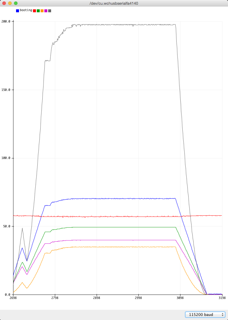 It has been a bit of work and some frustration this weekend but things are in a good place for me to start work on mppt code. I have seen the simulated solar panel, effected from a buck converter and some custom code does not work at all well. I had to chuck that idea in the round file bin and think again. What resulted is I have hacked into the Manson 30V 5A bench supply and have janked into the current limit circuit. This as it happens rides on the high side of the output, 30V. All I needed was to alter the voltage across the 5K pot. Thinking why not use a digital pot (they are isolated from SPI or I2C bus, great!) but I did not have any at hand. The solution and it is an ugly one but it works - was to capacitively couple PWM to the two terminals of the 5K pot. Again, I used an Arduino Uno. Some simple code and a voltage divider giving the code the output voltage lets me produce a solar panel-esq Current v Voltage curve. Much better. The code outputs a PWM depending upon the bench supply's output voltage. I get something like 4.5A constant current limit from 5V up to 25V and then linearly reduce the current limit from 4.5A to 1A at 30V. Somewhere around 25V is maximum power (25V x 4.5A) and my mppt code had better find it. Probably next weekend is the time to develop some working mppt code that uses real world data acquired from noisy and relatively low resolution sources. wronger than a phone book full of wrong phone numbers |
||||
| poida Guru Joined: 02/02/2017 Location: AustraliaPosts: 1482 |
Mark, there will be user defined maximum output current. For two reasons at least: 1 to protect the device 2 to protect the battery This is a primary design outcome of the controller. wronger than a phone book full of wrong phone numbers |
||||
| renewableMark Guru Joined: 09/12/2017 Location: AustraliaPosts: 1679 |
Thanks mate, is it feasible to have a few units running and have them talking to each other and have a total amps output limit on the combined output? There might be a scenario where 4 units are running. Each one having 40A potential, if max on each one is set to 40A then at Noon sun there may be a total of over 120A which may be too much for a particular bank. When it's cloudy, you want each one running max. You could overcome the overall max amps problem by setting each one to max 25A. But in the morning an east array could be producing a welcome 40A, so that wouldn't want to be wasted of course. It's a tricky issue, I have no idea how easy it is to fix with software. Cheers Caveman Mark Off grid eastern Melb |
||||
| Warpspeed Guru Joined: 09/08/2007 Location: AustraliaPosts: 4406 |
Peter, I have attempted to build a few of these myself over the years, and its a very difficult and frustrating thing to get working without hitting some nasty control loop characteristics. I would very respectfully like to suggest some of the problems I struck and what I did about them. Flat out full power MPPT duty cycle control is dead easy, no issues, its all as simple as it appears. Constant current maximum charge limiting should be pretty straightforward too. The knotty problem happens during the final stages of absorb charging, where you need to throttle back the current very low to maintain a constant battery terminal voltage. In theory it should be controllable right down to zero power flow, but the buck converter will definitely go discontinuous on you at some point. When that happens, the entire control loop changes its characteristics drastically, and your very careful PID tuning suddenly turns to crap, and the whole thing goes totally haywire. I wrestled with this problem for a very long time, and never solved it entirely. Even my backup commercial Chinese Blue Sky charge controller goes a bit spastic in the final stages of absorb charge, but the current jumping around all over the place does not seem to cause any problems with the battery. It just looks ugly on my digital amp meter. Anyhow, my best shot at this so far, has been to use two control loops. A fast acting inner control loop to keep the buck converter on the rails, and a very slow acting outer control loop to adjust the power flow to your algorithm of choice. I have had great success with a hysteric buck regulator that self oscillates, maintaining a constant low amplitude output ripple current. The whole thing is just an oscillator, and the frequency and duty cycle self adjust over a very wide range, so it never goes discontinuous. Just have the software set an output current set point with an d/a converter, and the hysteric regulator switches on and off either side of that set point. There is no PID to tune, and transient response is excellent without any stability issues (is oscillating already!) Your top level software algorithm just commands the hysteric regulator what the output current needs to be to do the job. It requires a very high inductance choke and a Hall sensor, and the small amplitude triangular ripple current coming from the Hall sensor switches the buck converter on and off. Its really simple, easy to get going, and trouble free. There are probably better approaches to this, but this has given me my best results so far after a lot of different attempts and failures. Cheers, ĀTony. |
||||
| poida Guru Joined: 02/02/2017 Location: AustraliaPosts: 1482 |
initial fun with mppt simulation. The below code makes a simulated solar panel with a certain current/volts curve. Green is current, light Blue is power, the X axis is volts. The cross is where the mppt algorithm is at any time. The noise can be controlled by pressing "n" or "N" to decrease/increase It seems the mppt algo has stuffed up and not found max power. It does find it easily with zero noise. 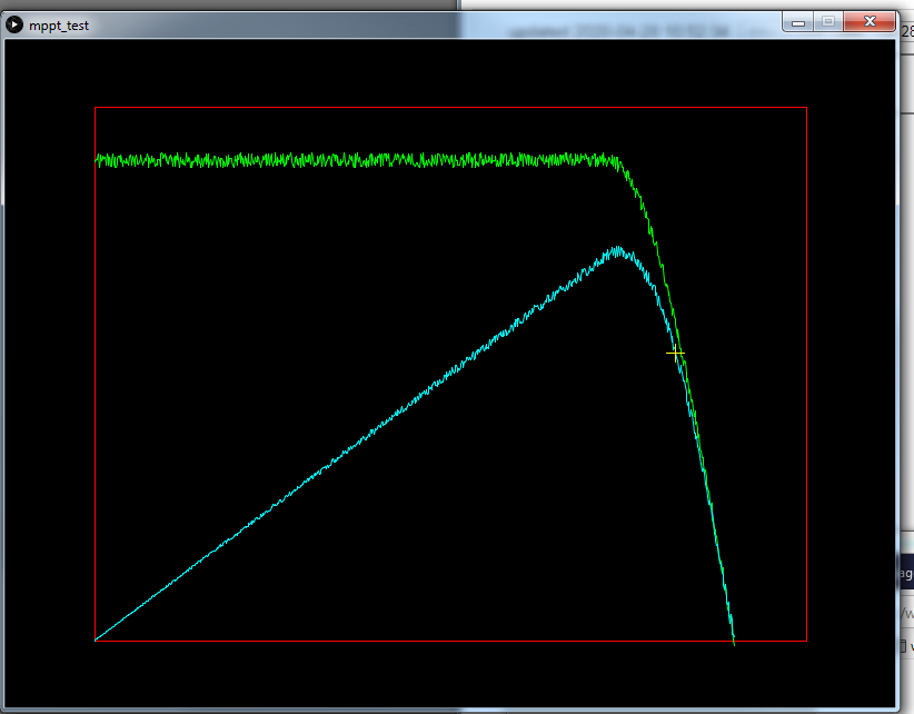 to run this, you will need "Processing" a free and open source programming environment I would put it in the CODE /CODE container but that removes square backets and that is a pain. float[] volts,amps; int np, pwm; float vknee, vmax, imax,gr; float pwr, old_pwr; int pwm_dir; float sx,sy,ox,oy; void setup() { np = 800; // the number of pwm steps volts = new float[np]; amps = new float[np]; pwm = 10; // just start somewhere vmax = 50.0; vknee = 40.0; imax = 10.0; gr = 0.15; // random (+/- this) is added to amps size(800,600); ox = 0.1 * width; oy = 0.9 * height; sx = 0.8 * width; sy = -0.8 * height; init(); draw_it(); old_pwr = 0.0; } void init() { int i,k; float v,kv,t; for (i=0; i < np; i++) { v = 50.0 * (float)(i)/(float)(np-1); if (v < vknee) amps[i] = imax ; else { t = (vmax - v)/(vmax - vknee); kv = cos((1.0 - t)*3.14159*0.5); amps[i] = kv * imax ; } volts[i] = v; } } void draw_it() { int i,k; float v,kv,t; background(0); float x,y,x2,y2; stroke(255,0,0); line(ox,oy,ox,oy+sy); line(ox,oy+sy,ox+sx,oy+sy); line(ox+sx,oy+sy,ox+sx,oy); line(ox+sx,oy,ox,oy); stroke(0,255,0); x2=0; y2=0; for(i=0,k=0; i < np; i++) { x = ox + sx * 0.9 * (float)(i)/(float)np; y = oy + sy * 0.9 * (random(-gr,gr) + amps[i])/imax; if(k == 0) { k=1; line(x,y,x,y); } else { line(x2,y2,x,y); } x2=x; y2=y; } stroke(0,255,255); x2=0; y2=0; for(i=0,k=0; i < np; i++) { x = ox + sx * 0.9 * (float)(i)/(float)np; y = oy + sy * 0.9 * ((random(-gr,gr) + amps[i])/imax)*(volts[i]/vmax); if(k == 0) { k=1; line(x,y,x,y); } else { line(x2,y2,x,y); } x2=x; y2=y; } } void draw() { float x,y; // perturb and observe // A naive approach - works with noise free data // but NFG when there is noise. // get the power now pwr = volts[pwm] * (amps[pwm] + random(-gr,gr)); // has it increased since last time? if so, keep increasing voltage (or pwm, same thing) if (pwr > old_pwr) pwm_dir = 5; // has it decreased since last time, if so, keep decreasing voltage if (pwr < old_pwr) pwm_dir = -5; // alter the voltage as required pwm += pwm_dir; // and record the current operating power for next time through the loop old_pwr = pwr; if (pwm < 1) pwm = 1; if (pwm >= np) pwm = np-1; // draw a cross where pwm is (i.e. operating voltage) draw_it(); stroke(255,255,0); x = ox + sx * 0.9 * (float)(pwm)/(float)np; y = oy + sy * 0.9 * (amps[pwm]/imax)*(volts[pwm]/vmax); line(x-8,y,x+8,y); line(x,y-8,x,y+8); } void keyReleased() { if (key == 'n') gr *= 0.7; if (key == 'N') gr *= 1.5; } wronger than a phone book full of wrong phone numbers |
||||
| noneyabussiness Guru Joined: 31/07/2017 Location: AustraliaPosts: 527 |
rs current sense A suggestion for the current sense, i know its a little late, but this part can use virtually any current shunt, with calculations made in software... very easy to communicate with, and accurate... I used this part on a project recently, and was impressive... better by far than using a standard rail to rail op amp in differential mode.. I think it works !! |
||||
| wiseguy Guru Joined: 21/06/2018 Location: AustraliaPosts: 1298 |
Hi Peter, as you know software is not my forte but I have been looking at and trying to understand the code. I am not sure about the section that says increase voltage or pwm same thing. Maybe this is a source of the behaviour that you are not happy with. To me voltage when charging a battery will remain constant (output side not input) however current and power are variables we can watch and alter. ĀThe input volts are part of the discussion and max power occurs around the knee, altering pwm will alter the current and therefore power however as we increase PWM the current to the battery will increase but as current increases the input voltage decreases. ĀOutput or battery voltage will stay quite stable in this process - if you are using a resistive load then it behaves totally differently to a fixed voltage sink load (battery). The part that read "increase voltage or pwm same thing" doesn't apply to the input or output volts in normal operation ? I havent really thought much about it but max power to a resistive load and max power to a battery will probably occur at different places - I have to go out right now will think a bit more about this on my return. So maybe I just dont understand your code and you already know all this but thought I would mention it in case it helps. Edited 2020-04-28 12:45 by wiseguy If at first you dont succeed, I suggest you avoid sky diving.... Cheers Mike |
||||
| The Back Shed's forum code is written, and hosted, in Australia. | © JAQ Software 2026 |
