
|
|
Forum Index : Electronics : 150V 45A MPPT - roll your own
| Author | Message | ||||
renewableMark Guru Joined: 09/12/2017 Location: AustraliaPosts: 1678 |
What are the carriers doing? Placing chinese products in quarantine for a few weeks before touching it and passing it on? Wouldn't blame them. the bits that come in the letterbox have been sodden with glen 20 before I touch them. Cheers Caveman Mark Off grid eastern Melb |
||||
| Volhout Guru Joined: 05/03/2018 Location: NetherlandsPosts: 3590 |
Yes, that is very good practise. @ capacitors parallel with different values. That will give a wideband decoupling. Excellent. Volhout PicomiteVGA PETSCII ROBOTS |
||||
| poida Guru Joined: 02/02/2017 Location: AustraliaPosts: 1392 |
Here is the tracking for AusPost They've had it since 2nd April. Nothing but praise for JCLPCB. wronger than a phone book full of wrong phone numbers |
||||
| renewableMark Guru Joined: 09/12/2017 Location: AustraliaPosts: 1678 |
Yeah, oz post are certainly in go slow mode. I got sent something express post (next day), it was meant to be here Tuesday, but only got here today (thursday). Maybe they have all joined a union, I explained to my son today union workers lean on shovels, smoke ciggarettes and eat meat pies watching the private contractors work. They get paid nicely each week, while the contractors send their bills in and get stuffed around for months to finally get their money, months after spending big $ on materials to do the job they were "so lucky to get" You can guess I don't do work for builders anymore and give them a dirty tirade when they call, most hang up after a minute, but some will cop a good 5 minuites of a blasting before hanging up. Cheers Caveman Mark Off grid eastern Melb |
||||
| poida Guru Joined: 02/02/2017 Location: AustraliaPosts: 1392 |
So I just tried the small ferrite bead on the drain of the switch. Oscillations are back. 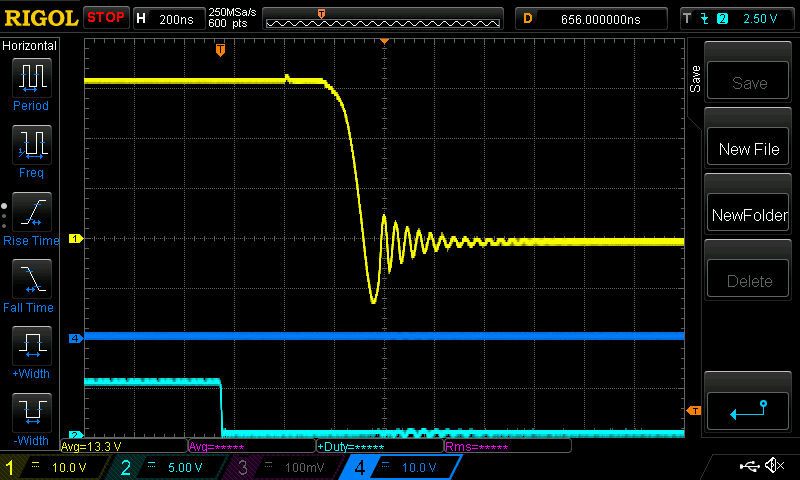 and with no bead 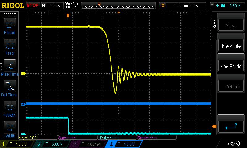 Hardly any difference with or without a bead on the drain. So the bead stays on the source. The input current, for the standard test case of 30V in and 15V/5A out is for the three cases of bead on drain, no bead and bead on source: 2.63A, 2.64A, 2.65A with uncertainties of about +/- 0.03A Efficiency for the bead on source situation is 93-94% The next problem is a DC load of a good size. I want to have a variable load for 50V at 45A. This means the load will be 1 Ohm at full power. I like the idea of a 1 Ohm resistor in a bucket of water, with the 50V switched into it using a 20KHz PWM. I might only need a couple of HY4008 for this. Stick them on a heatsink, drive their gates with a TLP250 or IR22184 or something. No need to get too precious with it. Have a potentiometer controlling PWM duty cycle. I would be wise to wind the 1 Ohm resistor in a way to minimise inductance (1/2 turns one way, and 1/2 turns the opposite way) 50V at 50A = 2500W and that is as powerful as a hot water urn or kettle. Probably can't use copper wire, I would need 46 metres of 1mm diameter copper when it's 7mOhom/foot. Steel wire maybe? The small galavinised wire 0.75mm diameter from Bunnings is about 0.45 Ohm/foot Maybe use a couple of 4 foot lengths in parallel, in water. This is what the weekend is for. wronger than a phone book full of wrong phone numbers |
||||
| Volhout Guru Joined: 05/03/2018 Location: NetherlandsPosts: 3590 |
hi poida, In the past I used to buy a few of these cheap electric heaters (fan an heater wire in one housing). These where damn cheap (some 20 dollar). And you could vary the load by turning heaters ON and OFF (sometimes they even have a half power setting). Not sure however if the fans work at DC... Volhout PicomiteVGA PETSCII ROBOTS |
||||
| poida Guru Joined: 02/02/2017 Location: AustraliaPosts: 1392 |
Lightning struck the lavatory (as my dad would say) The boards have arrived. Top quality as always. I plan to build 2 boards, one for software development and various investigations such as sensed input quality and noise levels, etc. The other is to be used as a MPPT charge controller, taking over from the 45A Morningstar PWM. And tomorrow I build the 50A DC load. Good grief...50A DC load..am I on drugs or what? wronger than a phone book full of wrong phone numbers |
||||
| wiseguy Guru Joined: 21/06/2018 Location: AustraliaPosts: 1017 |
Nah your not on drugs but they may be required later.... Cant you use a grid feed inverter to just send the energy back to the mains? Good way to get rid of excess energy & doesn't need a heat sink ! Second idea power up a 48V inverter and run a 240V 2.4kW fan heater ? Edited 2020-04-17 20:58 by wiseguy If at first you dont succeed, I suggest you avoid sky diving.... Cheers Mike |
||||
| Solar Mike Guru Joined: 08/02/2015 Location: New ZealandPosts: 1129 |
Last time I made a load like that was many years ago, used a 555 timer with adjustable duty cycle switching npn transistors driving 2N3055 power devices; the resistance coil was wound on a ceramic former submerged in a 4l tin of transformer oil. Mosfets are easier to use here, BUT... you will need an inductive choke in series with your circuit to average out the pwm pulses to a more constant current load, else the test PV controller sense circuitry will see a very non linear load, may upset it a bit. Cheers Mike |
||||
| poida Guru Joined: 02/02/2017 Location: AustraliaPosts: 1392 |
Thanks Mike and Mike and Volhout for the advice. I built the first board today using 150V FDH055N15A MOSFETS and HY5110 as diodes with gate tied to source. 2x each. 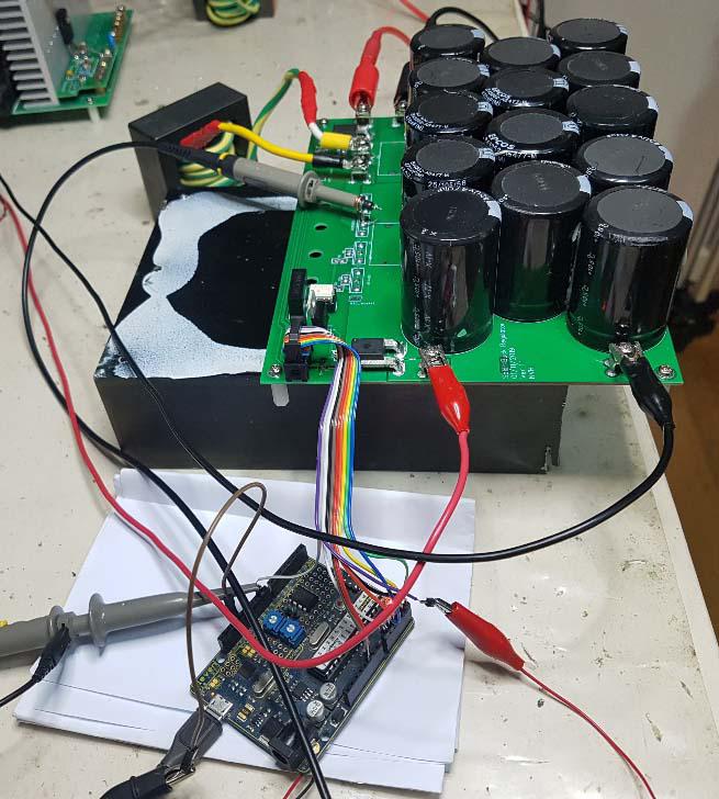 30V 2.71A in, 15.6V 5A out. Efficiency is (15.6 x 5) / (30 x 2.71) = 95.9 % Oh yeah. It appears to me quite clearly it's beer o'clock. wronger than a phone book full of wrong phone numbers |
||||
| nickskethisniks Guru Joined: 17/10/2017 Location: BelgiumPosts: 428 |
OH  It's so rewarding seeing someone used my design .I hope transmitted noise, EMI, stuf like that is not to high due to pcb layout. I've tried to keep the powerpart and signal lines away from each other. Put a foil (MKT)capacitor close to Drain and GND, mosfets and diodes close to each other. Maybe adding a 100nF ceramic close to drain and gnd would benefit the design. Don't know if the MKT on the output is a benefit. The list of the things you can test now is endless.  I keep following this thread with great interest! |
||||
| poida Guru Joined: 02/02/2017 Location: AustraliaPosts: 1392 |
Nicks, EMI is big. But your PCB layout is good I think. here is a plot of PWM% x 100, Vin, Vout, Iout, Iin Blue: PWM Red: Vin = Volts input Green: Vout = Volts output Purple: Iout = current output, uncalibrated, in ADC counts Orange: Iin = current input, uncalibrated, in ADC counts 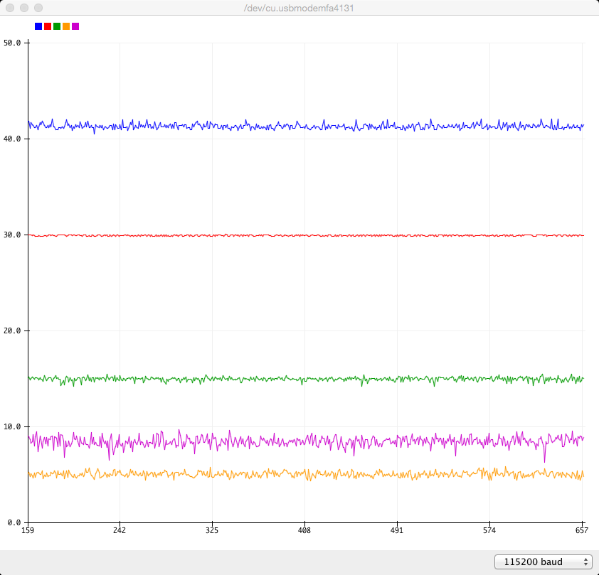 lots of noise. The PWM is driven by the output voltage, which contains noise. I think I will make a small board that has an Arduino Nano on it and some low pass filtering within millimeters of the Nano ADC inputs. Even 5 inches of wiring from the 10 wire ribbon from the the PCB picks up a lot of EMI. It is hard to filter out high frequency EMI that is of a higher frequency than the sample rate. Always there will be aliasing of those high frequencies, unless we LP filter it prior to sampling. The current sensors used with this board are not genuine parts, they are some I got from aliexpress for less money and I thought "are they any good?" Well, they are about 1 ADC count = 0.66 Amps and there is a lot of noise from the buck converter. I think the PCB is nearly exactly correct. Maybe a few things can be done (silk screen showing resistor and cap values..) Some snubbing of the switch/inductor node will be good too. I just placed a 104 cap and 100R in series with that node and ground. 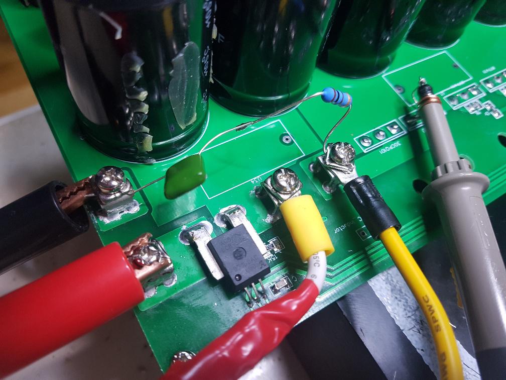 before: 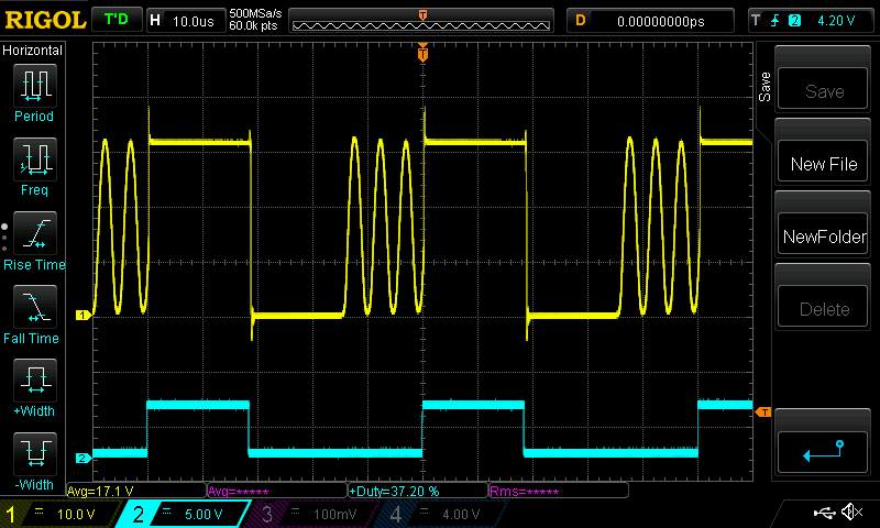 after: 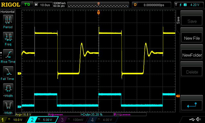 I just guessed some values, of course better values will have even less oscillation. That is, critically damped. Probably tomorrow I try with 53V in and 25V out to see how things go. (I think the HY5110 is a better and cheaper diode than the one you used in your system. But I am always happy to be proven incorrect... )Edited 2020-04-18 21:32 by poida wronger than a phone book full of wrong phone numbers |
||||
| poida Guru Joined: 02/02/2017 Location: AustraliaPosts: 1392 |
But please note, this is only 30V in, 15V out at about 2 Amps so it's running discontinuous. I expect it to be in continuous mode for most of it's operating life. So those oscillations are not very important. among may variations in your design, I used 470uF 450 caps. These were available at zero cost from defunct Areosharp inverter boards I had. I know you used 1,000uF caps. That will smooth out the output a bit more. I just checked, there is only +/- 100mV ripple on the output at 15V at 6 Amps. Maybe the caps are enough for these low power tests. Edited 2020-04-18 21:47 by poida wronger than a phone book full of wrong phone numbers |
||||
| poida Guru Joined: 02/02/2017 Location: AustraliaPosts: 1392 |
Now for a bit of pressure testing... I have the board now connected to a spare 48V SLA battery via some 4mm2 cables from 10 meters away. That is DC IN. There is a 20A AC contact breaker in series with the supply and it appears it's about as useful as tits on a bull. But it still functions as a switch. The load is a few meters of the 0.75mm galvanised steel wire, wound around a small concrete paving stone, all in a 10 litre bucket of (now quite warm!) water. It's resistance is about 1 Ohm. That is one Amp per Volt. 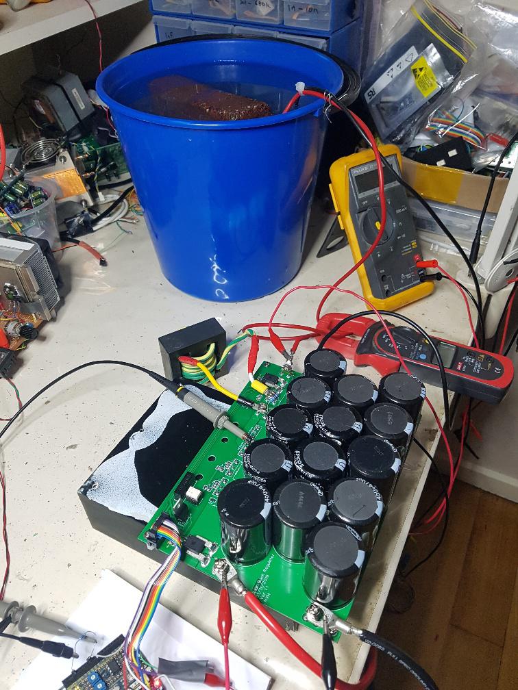 The below graph is the Arduino Serial Plotter output for Vin, Vout, Iin and Iout as Blue, Red, Green and Orange respectively. Calibration for current is a bit dodgy, I can not seem to get acceptable accuracy and offset nulling. The current sensors are about 0.7 Amps/ ADC count. That is not sensitive enough for me. No magic smoke was lost, even going to 40A or more. Nominal Vin is about 51V, I vary Vout via a potentiometer. There is something special about cranking up the output to 45V at 45A just from a simple twiddle of the fingers. POWER! 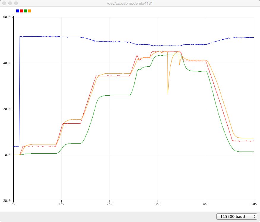 You can see the Orange line hit the hard limit of 45A and the PWM is quickly reduced, and then when reduced, it climbs back up again. I have no idea why the Output voltage did not drop as well. Nothing gets warm even during this test, except the water. The only thing that has increased in temperature is the inductor winding and that is only about 3 degrees more than ambient. The heatsink is still cold to touch. (150V MOSFETs, 100V HY5110 as diodes. 2x each.) This is going to fly I tells ya. Edited 2020-04-19 17:46 by poida wronger than a phone book full of wrong phone numbers |
||||
Ralph2k6 Senior Member Joined: 24/09/2017 Location: AustraliaPosts: 129 |
This has been an exciting journey Poida, thank you so much for sharing the grisly details as you progress. That efficiency is epic!  Ralph |
||||
| poida Guru Joined: 02/02/2017 Location: AustraliaPosts: 1392 |
I've nearly boiled the bucket of water. It's steaming. The only change is to use the Eltek 57V 2000W switchmode supply for DC IN. Below shows V set point, Vin, Vout, Iin, Iout which is Blue, Red, Green, Orange and Purple. I run it up to 1/2 power, then go to about 2060W. 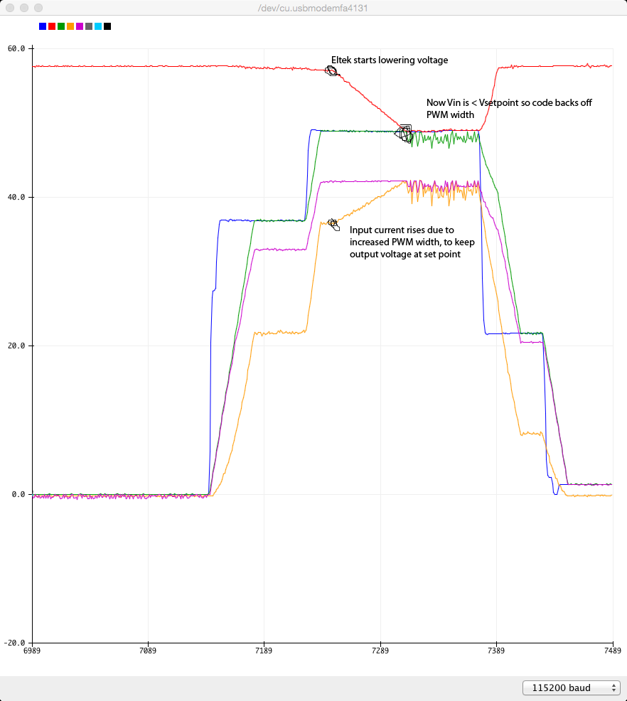 We can see the Eltek think "oh, more than 2000W, I will reduce voltage until things get acceptable" Meanwhile the buck converter increases PWM width due to falling input voltage. And then Vin becomes less than the set point voltage. My code then backs off PWM width until Vin is > V set point. Resulting from these tests today the heatsink gets about 5 C warmer, the inductor about the same. And I have some very disgusting smelling hot water in the bucket. Also I have this: 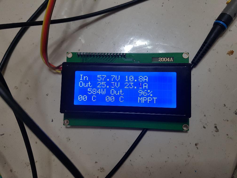 The converter's vital signs. It's only as accurate as the current sensor resoulution etc so I use it as a guide. For proper measurements I use the 3 Fluke DMMs and DC current meter. Edited 2020-04-20 15:37 by poida wronger than a phone book full of wrong phone numbers |
||||
| renewableMark Guru Joined: 09/12/2017 Location: AustraliaPosts: 1678 |
Nice work mate, looks like I'll have to put one of these on the project list. Still waiting for my BIG plug to hook into the changeover switch to finish off my Warpinverter project. What's the parts list for this unit? Cheers Caveman Mark Off grid eastern Melb |
||||
| Warpspeed Guru Joined: 09/08/2007 Location: AustraliaPosts: 4406 |
What kind of plug is that Mark ? + Cheers, �Tony. |
||||
| renewableMark Guru Joined: 09/12/2017 Location: AustraliaPosts: 1678 |
This one I have a changeover switch the sparky fitted to the cuircuit board in the house, that has cabling going to the garage where there is a socket that the inverter plugs into, currently that's the Madinverter, but I can just pull that plug and swap it out with whatever inverter or generator that has that corresponding plug to go into it. Cheers Caveman Mark Off grid eastern Melb |
||||
| poida Guru Joined: 02/02/2017 Location: AustraliaPosts: 1392 |
Mark, it's not ready for Prime Time Viewing yet. There are a couple of things I would want to change with the PCB. But you are looking at a handfull of SMD resistors and caps from Alltronics, about $10 2 x good 150V MOSFETS and 2x current sensors and one DC-DC converter from RS-Components, $38. You can find 14 x big capacitors from busted Areosharps or whatever, no need to fit 14 x 10,000uf in that case just fit 5 of those if you have them. I used the 470uF 450V items that were used in large numbers on the Aerosharp boards since they came for free. Thanks mate. The PCBs used 2 oz copper, the cost was about $100 for 5 boards, you could do it for less with slower delivery times. One 47uH big current inductor, using the big ferrite cores from RS-Compnents that I like. I am working on the design of the controller. It will be a small board with a 10 pin connector that goes to the main power board. It will work fine with or without the LCD. And it will need a 12V supply from battery to drive the small board as well as the DC-DC converter. And a big heatsink, probably any offcut from something we would have built as an inverter. The MOSFETS and MOSFET/diodes do not get hot at all. Anything would do if it weighs about 1 kg. Cost for me is $10(SMD bits) + $20 (PCB) + $38 for RS parts. I had the inductor and heatsink as spares. This is a 45A MPPT controller that will not need any cooling fan and will as a result run at high efficiency, for about $100. Victron offer one for $400. Yeah, but you can't repair it. Morningstar 45A MPPT is a lot more $$ and you can't repair it. (don't beleive me? ask them for a circuit diagram..) wronger than a phone book full of wrong phone numbers |
||||
