
|
|
Forum Index : Microcontroller and PC projects : HC-12 Wireless Serial Module
| Author | Message | ||||
| Alastair Senior Member Joined: 03/04/2017 Location: AustraliaPosts: 161 |
Tony, My comments were made more with hobbyists in mind rather than the education scene. Like Stan I still use the Picaxe for simple tasks but find the extra capabilities of the MM increasingly makes it the processor of choice. I taught in the University sector for many years and increasingly found that students were not interested in the history of technical development ie how we got to here and why. They saw little point in understanding what was inside the black box, just wanted to get on with the higher level stuff. 'Why learn what is inside the box and how it works? We just want to learn how to use the box.' Personally I believe that one cannot intelligently use a box unless you know how it works and hence its limitations. This is not the prevailing attitude now. The curriculum cram ie the vast amount of knowledge we need to impart also bears upon this. Anyway we seem to have strayed from the topic of this thread - the HC-12. cheers alastair Cheers, Alastair |
||||
GoodToGo! Senior Member Joined: 23/04/2017 Location: AustraliaPosts: 188 |
***Warning! Off Topic response below!!*** Back in the day, when I was getting all learned about the B727, we were taught the absolute in's and out's of the Sperry Sp50 and Sp150 autopilot as a part of the course. And I mean in's and out's, down to what each op-amp did. At the time I thought it was pretty pointless, after all, if it shat itself, you just 'changed the box'. However the 727 was a real troubleshooters jet. If there was a fault, out came the Wiring Diagram Manual, a multimeter and away you went. I always said it was a simple jet, but complicated. (Take a look in the cockpit to see what I mean about complicated) Fast forward to now, and with the 787, there is no, "what is inside the box" as a part of the course, as it's just chippery, and software (black magic). If it poops itself, you follow a Fault Isolation Manual, change the box, card, GPM or whatever, reload the software and away you go. It's now become a complicated jet, to make things simple. It's interesting watching younger guys (smart ones as well I might add), who don't have a solid background in troubleshooting, struggle with relatively easy faults, because they have followed the manual to it's conclusion and yet haven't been able to fix the defect. When gently 'shoved' in another direction, their eyes open wide and they usually remark "but the computer says......". Computer's lie sometimes..... I guess what I'm getting at, is that the goings on behind the scenes, aka blackbox stuff, has now become extremely involved and complicated, to make things easier for the end user. So while it's useful to know the limitations, etc, is it really important to know the absolute in's and out's of every 1 and 0 just to be able to use it? I don't know the inner workings of the Pic32 chip, but MMbasic has made it easy to work with. And I also reckon the whole workings of that goddamn Sperry Sp50 could now be done on a Micromite!  Think I might go have a glass of red........  Cheers! GTG! ...... Don't worry mate, it'll be GoodToGo! |
||||
| Intellecta Newbie Joined: 07/05/2016 Location: AustraliaPosts: 22 |
Dear Alastair, To stay on topic - just a short post. Was not comparing education applications, black box inside virtues of knowledge, etc, Just wanted to see if someone could consider a blockly type programming environment for the micromite. There is phenomenal horspepower in the forum. Maybe do a kickstarter or whatever. Seems to be a good environment for other chips. Tony Pugatschew |
||||
| Alastair Senior Member Joined: 03/04/2017 Location: AustraliaPosts: 161 |
*****further off topic warning*******javascript:AddSmileyIcon(' ')Tony, sorry if I got the wrong end of the stick. certainly a drag and drop IDE would speed development. I guess since the MM environment is largely not for profit, there is going to be a limit to the time folks can justify on building stuff. Having said that the talent certainly exists and many examples of shared code snippets attest to that. I recently started to use PureBasic for PC development of apps to primarily work with my MM projects. They have a number of productivity tools which will help greatly to speed development. The form designer - drag and drop especially. I have been toying with writing a tool for my own use to layout MM GUI elements with the code blocks standardised. There are a couple of intelligent touch displays which have this. If I do something I will put it up and then hope one of the bright young things will run with it! @GTG know exactly what you mean. A year or two ago a friend of mine was having trouble with the highly computerised engine in his 4wd. It would idle and run under light load ok but as soon as the foot went down it lacked power and ran rough. He had it in to the dealers who immediately connected up all the diagnostic gear but to no avail. Several hour$ later - sorry mate don't know. I was intrigued and asked him to start it up. It seemed ok but just did not sound quite right at idle. Being an old timer I used a piece wood dowel to act as a 'stethoscope' ie put one end on the engine and the other on the skull near your ear and you can hear all the noises. One of the injectors sounded different to the others. I bet him that it was dirty/blocked/sticking. No fault code as it was electrically ok. He took it out and had it cleaned - problem solved. Not claiming to be especially smart - just that I was focused on the symptoms and observations not what the computer said. Hope the red was a good one. As I get older I won't waste time on cheap wine there are only so many glasses left. Just received an E28 from Rictech in NZ. What a lovely little module. Looking forward to trialing it for some simple projects I have in mind. cheers Cheers, Alastair |
||||
| manuka Newbie Joined: 18/12/2006 Location: New ZealandPosts: 19 |
Great posts guys,especially Alistair's "pointed stick",& although tending OT I feel a Kiwi comment called for ! As a career e-educator (community college/university-but now retired) I often encountered issues re "a need to know the basics". Although these may help firm up students academic rigour,some content tended padding (often with little application) dubiously added by course supervisors... Given the white hot e-pace,clashes tended to develop with what SHOULD have been covered - back in the mid '90s datacomms & the Internet in particular (then WiFi in the early 2000s) tended ignored in preference to the likes of Maths. Nerds may have great software insights but lamentable communications skills. Best not get me going on tool usage - I've had students who've never stripped a wire & seen the copper inside for heavens sake ! Course content is endlessly debateable -who knows what won't later be useful? Case study 1: Near the end of an intensive year long PC/networking slanted electronics course I'd a commercial employer (instrumentation & petrol pumps etc) phone in asking for "start ASAP" prospects. Aside from e-skills his firm needed a NZ mains wiring certificate to be already passed. This cert. involved lots of Ohm's Law, First Aid, Aus/NZ standards & demonstrated safe mains wiring skills, & although easy enough was considered pretty basic & something few in the class of 30 had yet bothered looking at. Only a single student (& not the top one) HAD this cert. The lad promptly zipped downtown,was interviewed & firmed up the job by days end. He started as the course ended soon afterwards,at top $$$$$ + car. His nerdy mates were predictably green with envy. Case study 2: An old time WW2 digger (& radio ham) I knew in my teens related that he'd mentioned his Morse & radio skills at Army call up. He was promptly transferred to signals,promoted & went on to spend much of the bitter '44-'45 Italian winter campaign in a cozy radio truck while his mates were shivering in the blizzards. Case study 3: Although by then I'd put in a decade of senior high school teaching,the interviewer for a polytech position I'd applied for mentioned that my ham radio & e-hobbiest background was considered more valuable than my degree! (This was in 1979 & thus "pre PC") Stan. |
||||
| Alastair Senior Member Joined: 03/04/2017 Location: AustraliaPosts: 161 |
Oh dear, I had promised myself that I would not continue this off-topic thread diversion. but...... The following contains broad sweeping statements so do not be picky. There are/have been basically 3 approaches to the achievement of professional qualifications. 1. Apprenticeship style = start working on job and study in parallel. Emphasis on gaining practical skills and the knowledge base grows in parallel. 2. Undergraduate course with field work placements embedded. Intern year(s) following graduation to gain final accreditation. 3. Study any degree you wish to prove that you can assimilate knowledge, apply it, think and make logical conclusions. Preferably work in the real world for a period of time to gain 'life skills' and maturity. Enter a PG course in the specialised field often not having practical application until later in the course. Followed by internship and then right of practice. If the initial degree is not directly relevant then the student has more work to do. Outcomes show no significant difference after the initial early dropout is accepted. This is not greatly different to what is seen in style 2 courses due to aptitude and course awareness. There tend to be 3 classes of workers = A- will get hands dirty, B- may get hands dirty, C- prefer not to get hands dirty. Class A tend now to gain qualifications in course type 1. Class B have largely moved from style 1 to type 2 and some into type 3 Class C have increasingly moved from style 2 to 3. This is the trend in Aus and internationally. Old time practitioners tend to be highly critical of the day 1 performance of new workers and conveniently forget the intern aspect. Evidence after one to two decades suggests that after 3 years the new style practitioner is at least as capable as the old style and is able to operate far more flexibly in the modern workplace. They are adaptable and tend to take on more specialised training and change roles or fields. When I returned to academia after half a professional working life the above transitions were well underway. I was initially skeptical but became convinced that the results spoke for themselves. It definitely leads to a more flexible workforce which is essential in the modern world for both the workplace and worker. Able practitioners tend to succeed regardless of training. They learn the skills and knowledge required. If they move on, they adapt. We are still doing it. Even in our dotage we are learning new skills and exploring new areas. The comments we made earlier re unthinking reliance on technology is I would suggest a much broader issue. I see it everywhere. Google is your friend! Do not try and think through a problem just use technology to find the answer. If it does not pop out then ? I do think there is a great danger in the use of computers at the earliest ages in education. Kids need to learn to explore and think before they are immersed in the virtual world. @Stan - I really now think we should let this diversion die. In a real world we would continue over a glass of something - in this virtual world the thread needs to return. cheers Cheers, Alastair |
||||
| manuka Newbie Joined: 18/12/2006 Location: New ZealandPosts: 19 |
Alistair: Well said sir! I'm soon to "pop over the pond" for visits to family in Melbourne &/or friends up NSW coast,so we may well continue over a glass or two. Stan. |
||||
Grogster Admin Group Joined: 31/12/2012 Location: New ZealandPosts: 9981 |
[Quote=GoodToGo]It's now become a complicated jet, to make things simple.[/Quote] LOL!!! Well, quite. Smoke makes things work. When the smoke gets out, it stops! |
||||
| Paul_L Guru Joined: 03/03/2016 Location: United StatesPosts: 769 |
Not quite! The Pan Am 747s had three autopilot sets with each set consisting of a pitch computer, a separate roll computer, and an adapter box. Each of the three autopilots could use two different types of computers interchangeably, either a digital computer with a 24 bit word, or a mechanical analog computer. That's right, I said a mechanical analog computer complete with diaphragms, gears, servo motors, potentiometers, synchrotels, and jeweled bearings. Everything was fine as long as a given aircraft had a complete set of mechanical analog computers or digital computers. When you mixed analog and digital computers on the same aircraft things went to pot. If you wanted to let the autopilot actually land the aircraft, (it would usually make smoother landings than most pilots), you had to have two sets of autopilot computers turned on at the same time. The two sets would each produce slightly different correction commands and the adapter boxes would pick the SMALLEST correction to be applied to the airframe. If the adapter box thought the corrections the two autopilot sets were producing were too far apart it would suddenly turn all the autopilots off. The pilots were therefore required to follow the autopilot actions with their hands on the controls in case the darn thing suddenly disconnected at 150 feet of altitude when you begin to pull the nose up and hopefully reduce the descent rate to near zero when the wheels finally hit the ground. When you had a mix of digital and analog computers operating simultaneously the adapter would see the pulsating corrections produced by the 24 bit digital computer, compare it to the very smooth corrections produced by the mechanical analog computer in the other channel, decide that something was wrong, and disconnect, suddenly leaving the pilots to land the aircraft. In places like AKL, CHC, SYD, DMK, and HKG the likelihood that more than one 747 would be on the ground at the same time was very low and the number of spare computers available was also very low so autopilot disconnects during landings were usually ignored. When the aircraft finally got to a main base like JFK, MIA or LAX the technicians would have to run out and swap computers between aircraft to try to get all analog or all digital computers on each aircraft. Those digital autopilot computers and the digital inertial navigation computers did not make heavy use of microprocessors. They were pretty much restricted to MSI and SSI technology where the internal lands were wider than 3 microns. They also required mostly MU metal shields on each IC. There were a lot of TTL chips in each computer and a lot of heavy metal shielding in the boxes! The problem was that, at high altitudes, the incidence of high energy particles, (mostly gamma particles), was high enough that internal lands smaller than 0.5 micron would have a short life expectancy because they could be pierced by these subatomic particles. The flight crew members were issued Rolex mechanical watches that went tick tock and had to wound by hand. The life expectancy of a digital watch at those altitudes was no more than three weeks on average. Putting electronic things on an aircraft leads to different problems! Paul in NY |
||||
| RossW Guru Joined: 25/02/2006 Location: AustraliaPosts: 495 |
I know this is quite an old post, but I've found it while searching for answers to my own HC-12 questions. I hope some of you chaps with more experience with these things can help me! I don't believe this statement. The channel spacing is 400KHz, I agree, but the bandwidth of the transmissions by the HC-12 are in the order of 25KHz. Let me back up a bit with my story, and then get to the question! I've built some devices which use the HC-12 as the communications element. We had some inter-operability problems with SOME HC-12 modules. The root cause of that has been identified (and subsequently found mentioned on this forum elsewhere) that some of the boards were transmitting (and presumably receiving) on a 25KHz wide chunk of spectrum centred on (for channel 1) of 433.4000 MHz, while the others were centred on about 433.420 MHz. The other thing that jumped out at me while investigating this, was that despite the modules claiming an output of +20dBm, I was measuring a power closer to -35dBm. I know many chinese specifications are "optomistic", but not 50dB worth! Fearing the spectrum analyser was crook, I used my Marconi sig gen, the same connectors and cables, and created a clean +10.0 dBm carrier at 433.4 MHz. The spectrum analyser showed the carrier exactly on frequency and at exactly 10.0 dBm (surprised me, I'd have expected 0.3dB or more loss from connectors and the short coax). Re-connected the HC12 and set it transmitting. Back to signals peaking at -35dBm. I've tried several different modules. Different IPEX->SMA cables, and get the same results to within 1 or 2 dBm. Cables are short (100mm IPEX->SMA tail, and 1m good quality test lead to the SA). Everything is terminated at the correct impedance. So my question is, am I mis-interpreting the +20dBm figure. Is there some spectral element I'm not taking into account? Does anyone have thoughts or ideas? Would posting pictures of what I'm seeing help? |
||||
| Grogster Admin Group Joined: 31/12/2012 Location: New ZealandPosts: 9981 |
Yes, please post pictures.  I assume that you are using antennas that are matched to the transmission frequency? I expect you are - you seem to know what you are doing RF-wise.  I mention it, as something like a bit of wire on the antenna connector is NOT a good frequency match, as your RF meter would be. Use frequency matched antennas, helical coils, or wavelength matched lengths of wire for the best results. Generally speaking, I have found the HC12 module to be very reliable indeed, and will run on the smell of an oily rag(read: gives a very good performance) with on-frequency antennas. The ones that are off frequency are instantly suspect for other issues not yet identified - such as doing odd thing if not correctly matched, or just general impedance matching issues - who knows. When the clones are used with the genuine item, the network becomes as deaf as a post, so there would be major receive sensitivity issues in a mixed-module network. Avoid like the plague, if you value your sanity. Are you using the off-frequency 'Clone' modules here, or have you now sourced some of the authentic HC12 modules? Do NOT mix-and-match clones with genuine ones - but I get the idea from your post above, that you are aware of that. I just want to hammer it home if there was any doubt. I now sell the genuine article from my website, sourced directly from the HC12 manufacturer, if you need to be sure you have the authentic device..... Smoke makes things work. When the smoke gets out, it stops! |
||||
| RossW Guru Joined: 25/02/2006 Location: AustraliaPosts: 495 |
I wish I'd known that a few days ago. We've just ordered and paid for 50 from the manufacturer ourselves! Anyhow, I'll set the kit back up and take some pics shortly. |
||||
| Grogster Admin Group Joined: 31/12/2012 Location: New ZealandPosts: 9981 |
Howdy. I have never had any issues at all with the genuine ones failing to communicate. The clones USUALLY work OK, so long as ALL of them are the same clones. Mix and match them, and you are going to have a hell of a time due to a roughly 37kHz frequency error on the clones - making them deaf as a post to the genuine transmissions.  Yes, the clones are very good. Visually, they look identical, so there is not much you can use to tell them apart from the genuine ones. The clones tend to have a thinner 'white-wash' looking silkscreen, whearas the genuine ones use a thicker, whiter silkscreen. Other then that, the look the same. Did you look at the thread we had here about this whole issue? It went on for several pages.... Basically, the only way to be really sure, is with a frequency counter, scanner radio or spectrum analyser. That, or know you have sourced them direct from the manufacturer, and don't get them via eBay or AliExpress as they could well be clones. EDIT: If you have a read through that thread(see page 6 for a scope image of the clone crystal vs genuine one), you will see that the clones seem to use sub-standard crystals. Apart from having a bad frequency error, they only offer about half the amplitude of the genuine ones. Both of those factors add up to very unreliable modules, and must be avoided at all costs if you value your sanity when using HC12's. Smoke makes things work. When the smoke gets out, it stops! |
||||
| RossW Guru Joined: 25/02/2006 Location: AustraliaPosts: 495 |
I've thrown a quick and dirty page with what images I could recover from my chat at the time with a friend, and added some words of explanation. I'll do some additional testing (as described) - is there anything else pertinent you'd like to see from it? |
||||
| RossW Guru Joined: 25/02/2006 Location: AustraliaPosts: 495 |
I hadn't, but I have now. My findings seem to completely support that (or it supports what I found, or something!). The frequency problem completely answers the interoperability issue. What I haven't found much (or anything) on is the power level issue. Have you looked at the power out of the modules? Is it (around) +20dBm, or more like -30dBm? If you are seeing power levels of +10dBm or more, I will be even more flummoxed! |
||||
| Grogster Admin Group Joined: 31/12/2012 Location: New ZealandPosts: 9981 |
I have always got the expected range out of the modules. Actually, MORE then the expected range, so they must be outputting the power they say. Last time I put them on the spectrum analyser, I was just wanting to look at the harmonics more then anything else, as I expected them to be noisy - for the price, something has to give, and usually it is the output filtering. But they were surprisingly clean - I was rather shocked by that, as I expected them to be spectrally horrible. I mean, they cost three bucks each from eBay! Because those tests revealed how clean they were, I have now started using them for pretty much everything. I will see if I can find the time to set one up on the analyser again, and measure it's output power, but with the range I get from them, I fully expect the output to be what they say it is. The RF chip is a 100mW transceiver, so..... HOW exactly are you mounting your HC12's to the PCB with the antennas? You seem to know your RF, so I don't expect you have done anything silly here, but I have to ask. 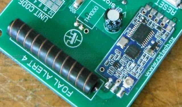 This is how I currently mount my HC12's, and they work very well. Note that I am also using antenna PCB track of 2mm which is a frequency match for around 433MHz. If your antenna is mounted externally via the UFL socket, then you really shouldn't be having any matching problems at all. Smoke makes things work. When the smoke gets out, it stops! |
||||
| RossW Guru Joined: 25/02/2006 Location: AustraliaPosts: 495 |
Yeah, that's what I figure too. And I've done a DC continuity test from the ant pin on the HC12 to the other end of the cable where it plugs into the SA incase any cable or connector was damaged - and I have DC continuity, and no short from centre pin to braid, so I'm puzzled. |
||||
f1fco Senior Member Joined: 18/03/2012 Location: FrancePosts: 155 |
hello to all, is it possible to order these PCBs ? and where ? or other PCB to use HC12 modules ??? thank you for information Pierre, from Nimes, south of France 73s de F1FCO |
||||
| RossW Guru Joined: 25/02/2006 Location: AustraliaPosts: 495 |
Hi Pierre, which boards do you mean? I'm not sure what environment Grogster's boards are for, but looking at what I can see, I suspect they're stand-alone with some microcontroller. The board I pictured is a multi-function board that piggy-backs on a Raspberry Pi, it wasn't intended as a "for sale" item, but if it suits peoples needs then I'm happy to supply them. |
||||
| Grogster Admin Group Joined: 31/12/2012 Location: New ZealandPosts: 9981 |
Ross - the only thing I can think that is different to how I am mounting the HC12, is that I totally get rid of any ground-plane around the module on my PCB footprint: 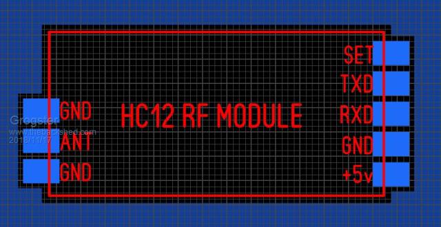 I always try to avoid running any tracks anywhere under this footprint, either on the top or the bottom copper. You use much more copper GP on your footprint, but I really don't see how that could lead to such a drastic drop-off in output power, but perhaps the GP on the HC12 and the GP under the module on the PCB footprint are acting as some kind of ground-coupling capacitor at RF frequencies. The fact that you get the expected output power with the module OFF the PCB seems to point to some issue with the PCB, if the power drops off when you put it back on the PCB. EDIT: I assume you have actually set the HC12 to run 100mW output power? I think they come from factory like that anyway, but you CAN change the output power via AT commands in setup mode. I expect you probably know that, but I have to ask to be sure that isn't the issue with your power output problem. Smoke makes things work. When the smoke gets out, it stops! |
||||
| The Back Shed's forum code is written, and hosted, in Australia. | © JAQ Software 2026 |
