
|
|
Forum Index : Microcontroller and PC projects : HC-12 Wireless Serial Module
| Author | Message | ||||
| RossW Guru Joined: 25/02/2006 Location: AustraliaPosts: 495 |
Yes, the modules are all set (while doing these tests) to full power with AT+P8 I've also tested using a tail soldered directly to the module, rather than using the IPEX connector, and still see signal levels at close to -30dBm |
||||
Grogster Admin Group Joined: 31/12/2012 Location: New ZealandPosts: 9082 |
Sorry, I must have read that wrong thinking you were getting full power off the PCB, but that it dropped when you put it on the PCB - my mistake. I have warmed up my spectrum analyser, and I am preparing a test jig so I can measure some power outputs. I still have some of the clone HC12's(well separated and marked from the genuine ones!), so I will test them both. Perhaps there is an output power problem too - anything is possible. Can I assume you are running your HC12's at 5v? They don't like 3v3, as only 100mV headway in the regulator spec. The HC12 datasheet does suggest they run at 3v3, but I have had issues with them at 3v3, and so have others, so best to stick to 5v. All my HC12's work flawlessly at 5v.  EDIT: [Quote=RossW]I made a small "beacon" yesterday from a picaxe and an HC12. Attached an LED to the picaxe, and sent a beacon out, then listened for an acknowledgement. If I got one, I blinked the LED again and waited 2 seconds. The receiver listened for a beacon, and if it got one, immediately sent an Ack. Thus, I could go walkabout and easily see where I stopped getting two-way comms. To my dismay, it was only about 50m at 1200 baud![/Quote] Use FU4 mode if you are going to run at 1200 baud. The increase in range in FU4 mode is very good. I run ALL my HC12's in FU4 mode at 1200 baud, and I can easily get 300 meters or so just using small helical antennas - and that is through walls and trees etc. I'm suspicious of the clones also having output power problems, based on the information you have supplied. I will get to testing the genuine and clone ones as soon as I can, but it will probably be a few hours from now, so don't hang about on the forum now.  Smoke makes things work. When the smoke gets out, it stops! |
||||
| RossW Guru Joined: 25/02/2006 Location: AustraliaPosts: 495 |
I have been running them in three different states, with what seems to be identical results. 1. 5.0V directly to the module. This was simply convenient, but they advise against it in use if a module is transmitting with high duty-cycle, due to overheating. 2. 5.0V through a single diode to drop about half a volt, with a low ESR cap directly across the power pins to the HC12 module. (Edit: from the datasheet, it says "Power supply input, DC3.2V-5.5V, with load capacity not less than 200mA. (Note: If the module is working in transmitting state for a long time, it is suggested that one 1N4007 diode should be connected in series when the power voltage is greater than 4.5V, to avoid heating of built-in LDO of module.)") 3. 3.3V sourced from the Raspberry PI onboard regulator. This was an experiment only, made no difference in any regard. (I was concerned about pumping 5V signals from the HC12 module straight into the serial input pin on the PI, which doesn't claim to be 5V tolerant. In practice, it seems to be happy with it, but on the next version of the board I've used a 3K3/2K2 divider to ensure the pi only gets a safe input voltage to its GPIO pins) |
||||
| Grogster Admin Group Joined: 31/12/2012 Location: New ZealandPosts: 9082 |
Well, I have had a chance to test both modules, and the genuine one registers fine on my SWR meter, but the clone has such a low output power, that it does not even see it - not a good sign. Here is the genuine HC12 result: 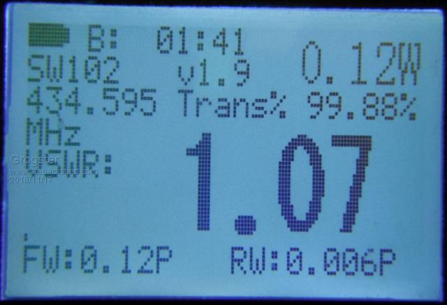 This module is set for FU4 mode, +20dBm output, and channel 4(434.6MHz). So, the SWR meter says we are actually getting 120mW out of it. Here is the clone on the spectrum analyser: 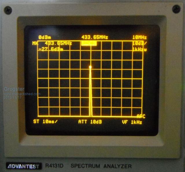 So, yes, about -30dB down. On this scope image, the very top line is 0dBm, so the marker is showing -27.6dBm - not very good. Data was just a stream of asterisk characters. I would manually stop the data-stream every so often, to prevent overheating the HC12 on-board regulator. Spectrum analyser shows the CF about 433.65MHz, even though this clone module was set to channel-1, which should be 433.400MHz or so - quite a wee way off frequency, this one....  Smoke makes things work. When the smoke gets out, it stops! |
||||
| RossW Guru Joined: 25/02/2006 Location: AustraliaPosts: 495 |
|
||||
| Grogster Admin Group Joined: 31/12/2012 Location: New ZealandPosts: 9082 |
Have a re-read of my edited post above. Both modules were set to different frequencies, as that is just how I picked them up. I don't think that invalidates the test though. The GENUINE one was set to 434.6MHz, and the SWR meter says it thinks it is 434.595MHz, which is close enough when compared to the clones. The CLONE one was set to 433.4MHz, and the SWR meter could not see it's transmissions at all. The spectrum analyser could see it on 433.65MHz - but at 30dB down.... I suspect that that sub-standard crystal is behind all of this. Not only is it badly off frequency(see other thread), but it is also less then half the amplitude of a genuine one. I fully expect that the crystal is used for both the frequency of operation, and as a reference for the modulation - which would explain why the signal is so weak coming out of it. EDIT: Haha! We crossed paths with our own edits.  Can you try one of the ones you have re-crystalled? It might actually show the correct frequency AND output power. Smoke makes things work. When the smoke gets out, it stops! |
||||
| Grogster Admin Group Joined: 31/12/2012 Location: New ZealandPosts: 9082 |
Here is a ZIP file with two short MP3 audio files in it, of the audio from each module. The clone one is very weak indeed. The genuine one has a nice crisp sounding data burble. 2018-11-17_180822_HC12_Sound.zip Smoke makes things work. When the smoke gets out, it stops! |
||||
| RossW Guru Joined: 25/02/2006 Location: AustraliaPosts: 495 |
I had high hopes also, but alas. Here's one of the clone boards, original crystal. Off-frequency by 31KHz (high), and output just on -30dBm: 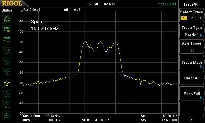 And after replacing the crystal, frequency is very close, signal unchanged:  Also, the range test with a beacon... I really struggled to get 40-50m range with a coil/spring antenna one end and a small whip antenna the other. Using the "halve the distance every time you reduce power by 6dB" guideline, and allowing for a modest antenna gain one end, I calculate about 14-28m range would be expected at -30dBm! That is scarily close to what I measured (compared to the expected 1000m+ in open air, which I had for the test) Edit: The beacon test, at 9600bps calculates out to 3m range, I was only getting 5m (indoors, but no direct obsticles, of course multipath and other noise may have come in to play). |
||||
| Grogster Admin Group Joined: 31/12/2012 Location: New ZealandPosts: 9082 |
I will be very interested in those same tests on your Rigol, but with the genuine article. I will have to look at getting one of those things. My poor old Avantest CRO SA is getting a bit long in the tooth.... It still does the job, but the newer units are full colour, much lighter, and you can export nice images like you did. I have to take photos of my SA screen - LOTS of photos, so I can pick out the one that is in focus. I will hook up a genuine one to my SA, and see if I can get some sort of useful image from it. Smoke makes things work. When the smoke gets out, it stops! |
||||
| RossW Guru Joined: 25/02/2006 Location: AustraliaPosts: 495 |
Oh, I'd love to keep this Rigol. My personal SA was on loan (An old Tektronix 492) and 1000km away. A friend has this Rigol. It only goes up to 1.5GHz, which unfortunately just doesn't go far enough for about 50% of my jobs. The Tek goes to 21GHz without an external mixer, but it is very heavy, very big, very monochrome and no chance of screen-captures. Rigol make one that goes to 7.5GHz and would do about 75% of my needs, but the cost of their 7.5GHz one is just too much for me to justify. (If it went to 19GHz or 20GHz, it might just tip the scales). |
||||
| Grogster Admin Group Joined: 31/12/2012 Location: New ZealandPosts: 9082 |
I hear you. My Avantest SA is a great bit of kit, but it is old amber monochrome CRT technology. It does go from DC up to 4GHz though, so it has a very useful frequency range. It also is quite big, bulky and reasonably heavy, so I tend to just leave it where it is unless I HAVE to take it somewhere. The new Rigol kind of SA are great for portability among other things, but yeah - they are still expensive bits of kit to own. I guess both you and I are quite lucky to have any kind of professional SA - many people simply can't afford them. I only bought this one as a 50/50 deal with my boss at the time, as both of us wanted one, but neither could really afford it. Even second hand, it cost us four grand. New ones were around ten grand at the time, so I still think it was an OK deal, and any reputable SA is build like a brick privy, so they usually give a very good service life - even second hand ones. Smoke makes things work. When the smoke gets out, it stops! |
||||
| RossW Guru Joined: 25/02/2006 Location: AustraliaPosts: 495 |
Well, the evidence is in. The answer is now absolute. Our shipment of genuine HC12 modules arrived a hour ago. I've dropped one onto a board and fired it up. 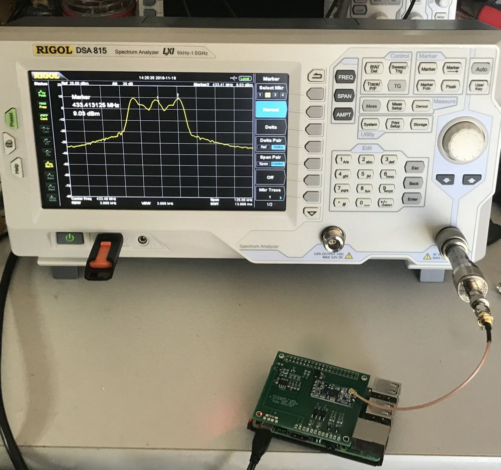 As you can see, it isn't pretty: * short IPEX->SMA(f) tail * SMA(m)->SMA(m) adapter * SMA(f)->N adapter * 10.0dB precision attenuator Connect to the Raspberry PI, check the module: $ ./hc AT+RX OK+B9600 OK+RC001 OK+RP:+20dBm OK+FU3 Check firmware version: $ ./hc AT+V www.hc01.com HC-12 v2.6 Set it to 1200 baud and re-check parameters: $ ./hc AT+B1200 OK+B1200 rossw@raspberrypi:~ $ ./hc 1200 AT+RX OK+B1200 OK+RC001 OK+RP:+20dBm OK+FU3 And then started transmitting data... 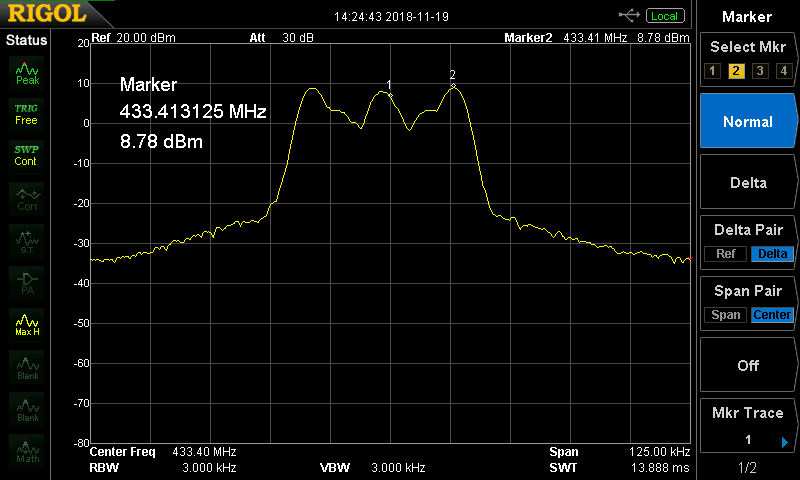 Note, it shows only 8.78dBm here (plus the 10dB attenuator makes it +18.78dBm), whereas in the photo above it had risen a little to +9.03dBm (+19.03dBm) Given the five connections, I'd say that's about bl00dy perfect, mate!! |
||||
| Grogster Admin Group Joined: 31/12/2012 Location: New ZealandPosts: 9082 |
So would I. And much in line with what I have come to expect with the genuine article. Thanks for sharing. This is useful data to have on the thread.So, other then a bad frequency error, the clones also have a very bad output power nowhere NEAR what the genuine ones have. Bloody Hell - YUK!    Smoke makes things work. When the smoke gets out, it stops! |
||||
| lizby Guru Joined: 17/05/2016 Location: United StatesPosts: 3027 |
Very helpful. I haven't been getting anticipated range from older HC12s that are probably clones. Time to chuck 'em and use the genuine articles which I've gotten from Grogster. PicoMite, Armmite F4, SensorKits, MMBasic Hardware, Games, etc. on fruitoftheshed |
||||
| JohnL Senior Member Joined: 10/01/2014 Location: SeychellesPosts: 128 |
You people do realize that transmitting at +20dbm on 430Mhz band is illegal in Australia and some other countries. Do a search, has been discussed in this forum. If you feel lucky and have $10k to burn. https://www.acma.gov.au/theACMA/engage-blogs/engage-blogs/Interference/Using-unlicensed-radios-a-costly-exercise There are other technologies and frequency band more suitable and appropriate than this, Google is your friend. |
||||
| Grogster Admin Group Joined: 31/12/2012 Location: New ZealandPosts: 9082 |
JohnL - Absolutely. No-one is talking about actually transmitting 100mW @ 433MHz, we are simply trying to establish if they can indeed do the output that is claimed of them. The clones cannot, the genuine ones can. Before use, they would need to have their output power pulled back to the band limits. But feeding it into a SA, you can measure those things, and in order to measure those things, you have to output the rated power of the device. The SA acts as a dummy load anyway, so even at +20dBm into the SA, they will radiate very little outside of the SA itself. The point being to find out if they are outputting the power they claim to be. Neither RossW nor myself were running them on-air at that frequency and power. EDIT: Your link does not seem to work. All I get is a black screen with a white circular segmented progress thing that goes around forever, but never comes back with anything to read. Smoke makes things work. When the smoke gets out, it stops! |
||||
| RossW Guru Joined: 25/02/2006 Location: AustraliaPosts: 495 |
As Grogster has already said... we are not transmitting at this power on 433.4, merely into a closed test environment (the spectrum analyser). I hold a full amateur license, and if I really wanted to do it, could easily pop a pair of these up into a part of the band I could, legally, transmit at that power. I may yet do that to do some range testing, but as Grogster said - we'd be setting them to a lower (legal) power limit depending on the antenna and feedline in use. In the case of the clone ones - running flat stick, they're still 40dB below the limit! |
||||
| RossW Guru Joined: 25/02/2006 Location: AustraliaPosts: 495 |
An update. Our newest batch of genuine boards straight from HC01.com is easily identified from the fakes/clones by virtue of the different processor chip! Fake/clone at the top, Genuine at the bottom in this picture: 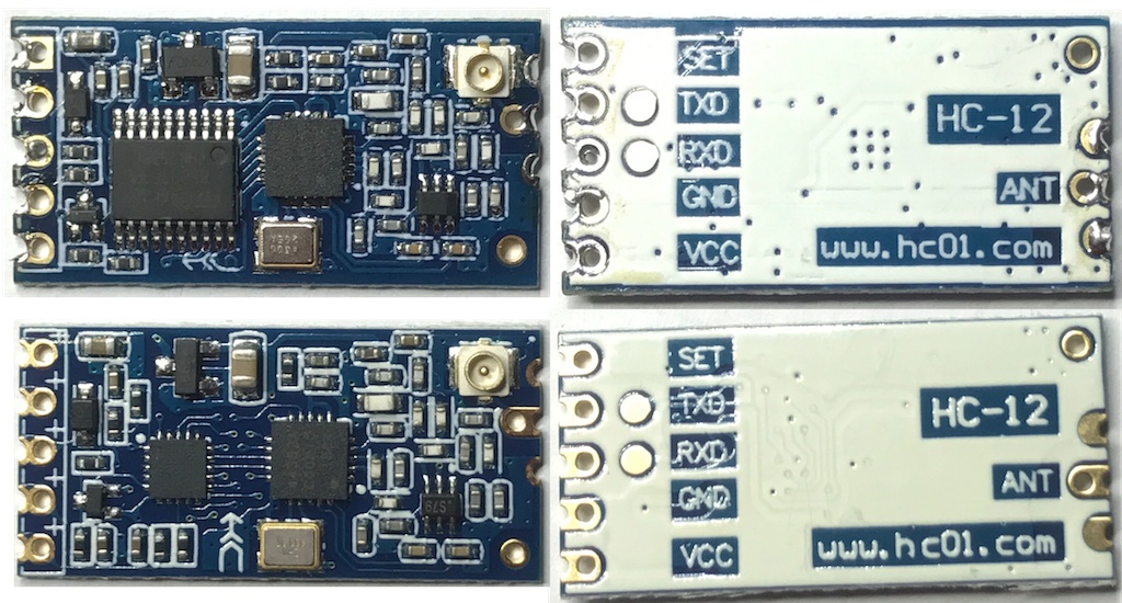 Additionally, we did some additional testing on some other boards. Seems there are "degrees of bad". Some other, older, clone boards which appeared to operate with reasonable distance were found to be somewhat off frequency (25KHz or so), but replacing the crystal brought them back on spec. Checking their power, again into the spectrum analyser - and they're at about +6dBm. Down 14dB on what they should be, but still 30dB or more above some of the other clone boards! There are clearly multiple levels of "good", "mediocre", "rubbish" and "just give me my money back!". Hope this helps someone else! |
||||
| Grogster Admin Group Joined: 31/12/2012 Location: New ZealandPosts: 9082 |
That's interesting that they have changed the processor chip. I note several other component positional changes too. Perhaps this was done in an effort to distinguish the genuine ones from the clones. That would work in the short term, but the cloners will just clone the newer module and before too long, we'll be back in the same state of affairs. But for right here, right now, this is a good thing, and makes the genuine ones really easy to spot. Smoke makes things work. When the smoke gets out, it stops! |
||||
Timbergetter Regular Member Joined: 08/10/2018 Location: AustraliaPosts: 55 |
I see that fake units may not come up to spec for power output. Could this be an issue when the unit is configured for 25 mW 14 dBm? Has anyone tested what maximum power you get with the AT+P6 setting? |
||||
