
|
|
Forum Index : Electronics : Bryan's Inverter build
| Author | Message | ||||
| Godoh Guru Joined: 26/09/2020 Location: AustraliaPosts: 675 |
Hi Bryan, I use double pole DC breakers on the input side of my GTI inverters and also double pole AC breakers on the output. The labels on my inverters say turn the output off first then the input to isolate them. Turning off the AC breakers on the output shuts them down by anti islanding then isolating the panels from them makes them safe to work on. 300 volts DC would be pretty nasty if it got hold of you. I run one of my GTI inverters at around 240 volts DC and the other is around 170 volts DC. I would have liked to keep the DC under the 120 volt level but the GTIs I have wont start up at that voltage. Have fun Glad to hear the ute just needed and oil change. Not sure why it would smoke so much and need a trailer but hopefully it is fixed Pete |
||||
Revlac Guru Joined: 31/12/2016 Location: AustraliaPosts: 1282 |
If you want to scratch off some of the conformal coating and solder some wire onto the board, some details Here And Here is the boards the code and setup, depends on which version you have, 2 resistor's on the power board were changed to 5K1, you might have done that all ready, there is version 1 and version 2 of the controller board if you use them or some other. Cheers Aaron Off The Grid |
||||
Bryan1 Guru Joined: 22/02/2006 Location: AustraliaPosts: 2138 |
Hi Aaron thanks for those links mate lots of good reading too  Anyway dusted all the cobwebs of the inverter board and the driver board and had jacked red back to contend with  Now as I do have the HY5608 fets I'm only going to 3 on each leg to start as if I do blow them it's only 12 fets gone to fet heaven. Got all the passives soldered in and this morning put all the 5 watt resistors on ready to solder in. Now with the fet spacing for the heatsinks it has been that long the grey matter has kicked in so if one does have that measurement it could save me from doing it more than once due to incorrect spacing. Regards Bryan Edit: Ok measuring with my Verniers I got 24.4mm spacing between the centre hole of the each mosfet. Edited 2025-09-07 15:26 by Bryan1 |
||||
| Bryan1 Guru Joined: 22/02/2006 Location: AustraliaPosts: 2138 |
Well finally got the main board all finished now silly me after drilling didn't take the heatsink off the mill and sure enough on the 11th hole broke a tap  O'well my 3mm taps have lasted well over 20 years so from then on took the heatsink off and deburred it and got the rest of the holes tapped. On one heatsink the original mounting hole on the Aerosharp got in the way but eh there is no real need to use 6 HY5608 fets each rail. O'well my 3mm taps have lasted well over 20 years so from then on took the heatsink off and deburred it and got the rest of the holes tapped. On one heatsink the original mounting hole on the Aerosharp got in the way but eh there is no real need to use 6 HY5608 fets each rail.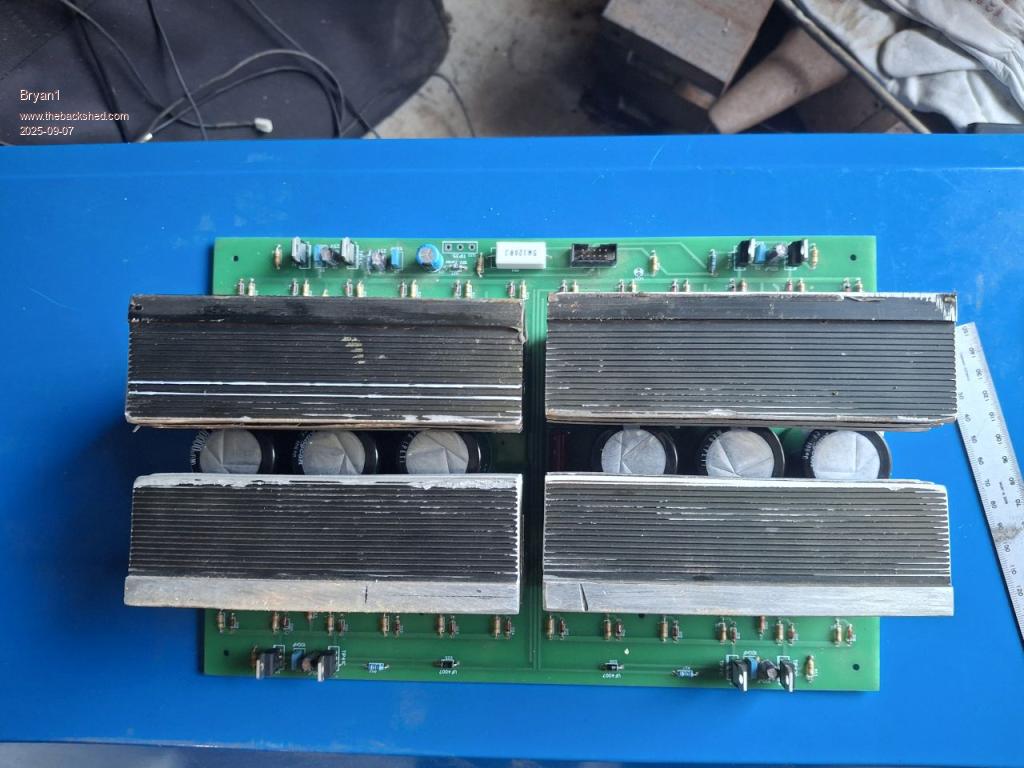 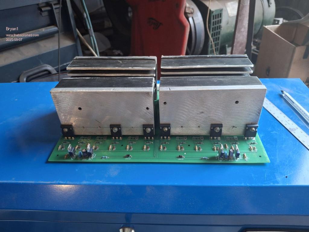 I still need to make some brackets to clamp the heatsinks and it does say the low side has to be isolated but this black duck doesn't know what side that is so once I do know I can join the heatsinks on the high side. Cheers Bryan |
||||
| poida Guru Joined: 02/02/2017 Location: AustraliaPosts: 1480 |
my 4 x 4 FET inverter is still going since about Aug 2019. I've seen 90+ AMPS at 50V into it. probably more. It might be a how to say.."not quite perfect design" but it does not die. IF.. if it has enough inductance at the highest DC current input and then some on the primary choke. And at high frequencies too. if there is not enough, the short high current spikes will munt the FETs. (munt being an Un Zud saying - waves to Solar Mike) best of luck and keep a few coldies in the fridge. wronger than a phone book full of wrong phone numbers |
||||
| Revlac Guru Joined: 31/12/2016 Location: AustraliaPosts: 1282 |
Hi Bryan, For some reason I thought you had the original Red MAD Boards, anyway I forget things as well, I have a set of these green PCB's that Poida posted on the forum some time back, haven't built the power board yet, but have completed 2 of the controller boards, On the Power PCB (the side that has the 10 pin connector) under the heatsink on the PCB it is marked VS1 and VS2 and are split heatsinks. Your build is looking good. Cheers Aaron Off The Grid |
||||
| Bryan1 Guru Joined: 22/02/2006 Location: AustraliaPosts: 2138 |
Poida our house Selectronic SA32 has been going 24/7 since'04 and my shed Kipoint inverter where I sent an email to them in '05 with the same spec's of the Selectronic they designed a 3Kw around the spec's. I also mentioned don't bother with a LCD as it die over time so it was left out.Now as I do have a heap of those HY5608 fets I will put one more on each leg so they run nice and cool under load. Edited 2025-09-07 19:42 by Bryan1 |
||||
| Bryan1 Guru Joined: 22/02/2006 Location: AustraliaPosts: 2138 |
Well finally got those 2 aerosharps home and man are they heavy so tomorrows job is opening them up to look at all the goodies and get the toroids out. I reckon I will use one of the cases for this inverter project too as the case looks to have plenty of room to fit everything. Edit: Well got the first toroid out 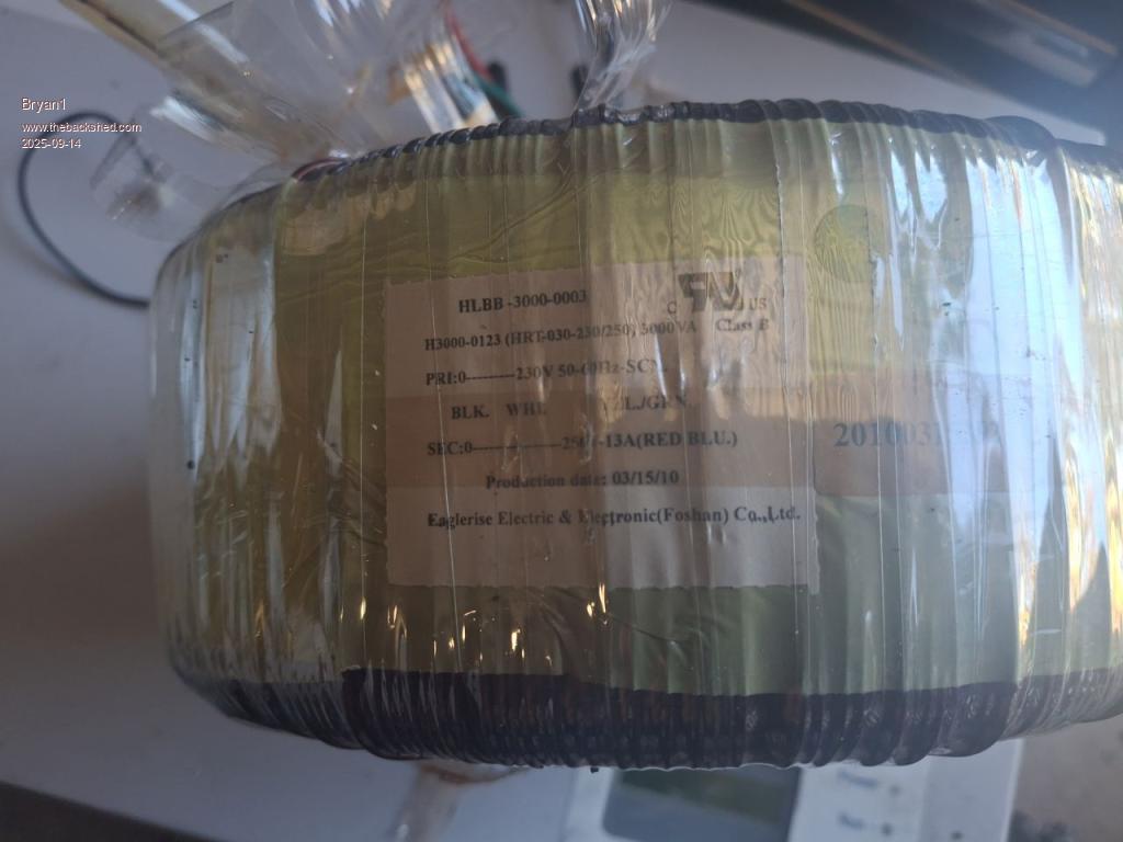 Now for a bit of cleanup and do the other one Edited 2025-09-14 09:49 by Bryan1 |
||||
| Bryan1 Guru Joined: 22/02/2006 Location: AustraliaPosts: 2138 |
Well got the second toroid out and while stripping it I did notice it was different to the first one with the large choke being a potted one. Now doing an ohm's check on both secondaries the difference betwwen them was 0.01 ohms where the first one was 0.26-0.27 ohms and the second 0.27-0.28 ohms 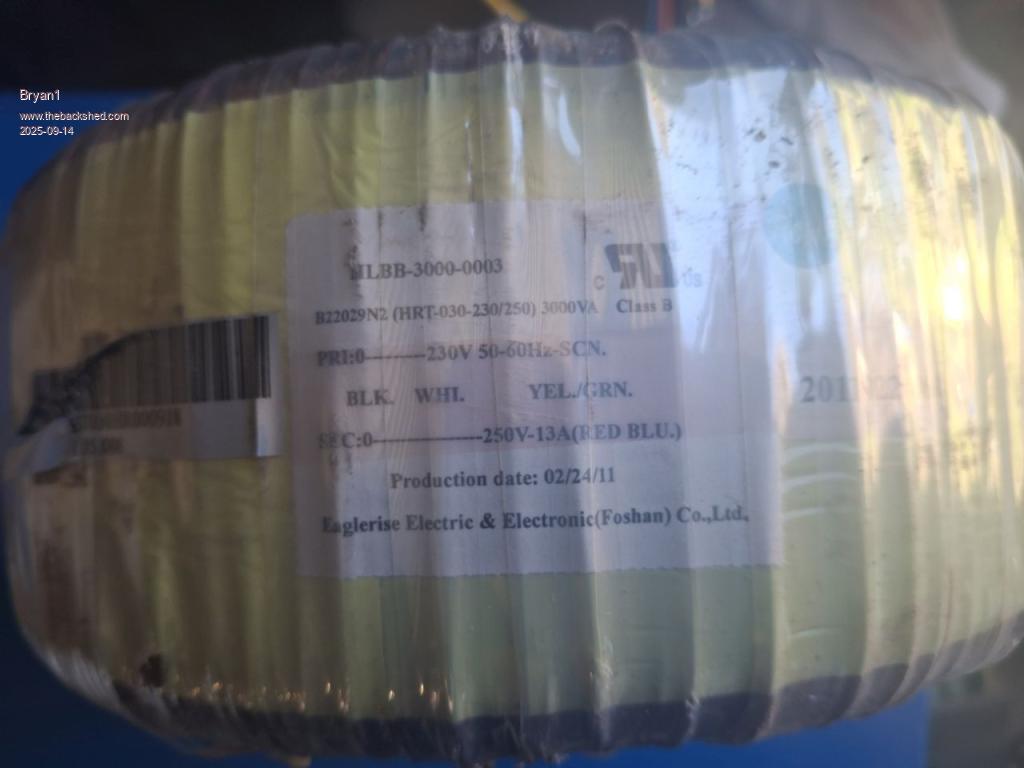 As one can see each grid tie has different build dates so I don't think it is worth the risk of stacking so just one toroid will be used. Now once I do get this Madboard inverter finished and working the other toroid can go one one of Mike's inverter boards where I still need to get a heap of parts for that build. Regards Bryan |
||||
| Godoh Guru Joined: 26/09/2020 Location: AustraliaPosts: 675 |
They look great Bryan. What wattage are you going for with the new inverter? Have fun with them. Pete |
||||
| KeepIS Guru Joined: 13/10/2014 Location: AustraliaPosts: 2196 |
It's a shame that the 250V windings are not the first winding on the cores, in any case I've started huge loads in testing with my own test aerosharp setup, using the 230v winding and 14 turn input winding, again, constant power level is only limited by the 230V winding size and how well you control the maximum core temperature under high constant loads. Of course if you decide to rewind from a bare core then you remove most of the limitations. Very Nice cores  NANO:Inverter V 8.2ks - Linux AvrDude GUI script V4.1 |
||||
| Bryan1 Guru Joined: 22/02/2006 Location: AustraliaPosts: 2138 |
Hi Pete by wattage did you mean voltage ??? if so 24 volts mate as those forklift batteries I put back in 2012 are still going strong so no need to setup to 48 volts for the next decade I reckon Keepis I've no intention of rewinding the cores as I like my fingers the way they are Now with the small hole in the core I'm glad to be on 24 volts as just to get 12 turns thru that hole is going to be a challenge let alone more turns for a 48 volt system.Now as you have plenty of experience with these cores which winding would be the best to use. Now on reading my double stacked thread by using a transformer one can excite the core so lets say I use 11 turns of wire for the primary then measure each winding to see where I can get the 220 volt output. By going this way I can deterime the number of turns on the primary if my thinking is right. Edited 2025-09-14 12:35 by Bryan1 |
||||
| Godoh Guru Joined: 26/09/2020 Location: AustraliaPosts: 675 |
Hi Bryan , no I meant what power output are you aiming for from the inverter. I know the transformers are 3kw, but with only 3 transistors a side, I was wondering how much power you are hoping to get from the inverter. As far as output voltage goes, I is probably better to aim higher than 220 volts. Otherwise on heavy loads the voltage may dip too low for starting heavy loads. I read that you are not going to unwind the transformers to make more room for the low voltage winding, I hope that you have enough room for the big cable. I rewound my stacked cores and took some laminations out of the middle to give me a 100 mm core diameter. That was only just enough for my low voltage winding to fit in. I used fibreglass insulated 12mm x 3 mm flat copper for my low voltage side. good luck Pete |
||||
| Bryan1 Guru Joined: 22/02/2006 Location: AustraliaPosts: 2138 |
Ah now I get you Pete well mate I am going to put one more fet on each bridge so it will be 4 0ff HY5608 mosfets so they should run nice and cool. Now my Unimig 182 states it needs 7Kva and I did try the mig out with that first inverter I made where it did work nicely doing a 100mm fillet weld using gasless wire Back in the day that Kipoint inverter took everything I threw at it but the day I arc welded the 2 ovens over a long day killed the surge on the Kipoint. Now as I do have that 100 litre milkcan boiler it would be nice to finally get it in use so I only need to a couple of runs a year. Now for the heating a 3.5K element is on all the time and a 2.4Kw element is on a voltage controller so I can see how the inverter goes with the 3.5Kw element and gradually bring the voltage on the 2.4Kw and see how it goes. As I am back working again my shed bank is fully charged for the weekend for me to play Now with 735AH traction battery there is plenty of power to be used.I do have that 3hp aircon on my shed wall and when I ran it on my 16hp listeroid alot of times when I hit the cool on the aircon the belt would come flying off due to the current draw where it acted like a brake on the 5Kw genhead. When I put the Kipoint inverter in it also ran it but most times it beeped saying over current. I do have a soft starter for it but never got a sparkie around to fit it. Down the track I do want to get a plasma cutter and I'll setup the air for it so a air compressor will also be in the mix. |
||||
| Bryan1 Guru Joined: 22/02/2006 Location: AustraliaPosts: 2138 |
So if I have this write the 230 volt primary is wound over the secondary so I can remove the primary to make more room for fitting the new primary for the inverter |
||||
| KeepIS Guru Joined: 13/10/2014 Location: AustraliaPosts: 2196 |
I think you will find that the 230V primary is the first winding on the core, the 250V winding (which would be ideal to use) is wound over the top of the 230v. I could be wrong, but from memory I think this is the PRI/SEC definitions they use. NANO:Inverter V 8.2ks - Linux AvrDude GUI script V4.1 |
||||
| Bryan1 Guru Joined: 22/02/2006 Location: AustraliaPosts: 2138 |
Thanks for that information Keepis I will take the insulation off one of the toroids for a look see some time this week. I got in touch with Poida and he sent me the ino files so one step closer to getting finished.Yesterday I fired up my old laptop with Linux on only to be told the OS wasn't supported anymore so tried the ethernet on my shed hub but it wouldn't connect so just used my phone. Downloaded the new OS and installed it along with all the updates etc and just under 5 gig was downloaded. So this week the job is to load all the programs on and the Arduino software will be the first one so I can load in the nano's with the software. |
||||
| Bryan1 Guru Joined: 22/02/2006 Location: AustraliaPosts: 2138 |
Another forum member has been in contact with me via PM and provided the best information on modifying these toroids Now I have asked permission to post the long explanation he provided so I am going to wait until I get the OK to put it in this thread.So basically unwind the 250 volt winding to expose the 230 volt primary then splice the primary and add 10 turns the same way as the winding. Then the message states hooking it up to my inverter output to check the voltage but until I do read this all again I won't any add more detail as more than likely it will be wrong. So this weekend I'm going to unwind one of the toroids so the primary winding is exposed then follow to the letter that PM as like I say it too good to keep private Now I do have another big choke from one of the inverters so the hunt for more of that 7x5 enameled wire is on so I can make another dual choke with 10 turns on each side that Tony put years ago as back in the day getting the most out of these Aerosharps was the go Now I could just use one of Mike's LCD boards but as I like a challenge and my CNC is going again doing a Sprint Layout design and milling a LCD board does seem very tempting The only thing left on the control board is soldering in the Nano and soldering in the Fets for fan outputs. The Fet driver chips and the LM358's have stayed in their packets and will be added when I'm ready to do the first test. Poida has provided me with the code for both the inverter and LCD and for the 15 volt input on the control board I did buy a buck converter board to use so I can use my power supply to power the control board to make sure my LCD board is working. Got some 6mm ali plate to connect the heatsinks and some perspex to stiffen the heatsinks. I have been brought out of retirement and got a great job designing guards on machines so no hands can be put in the wrong place so each night a bit more can be done so this project can move that closer. Now as this is a long post best to post it now To be continued |
||||
| Bryan1 Guru Joined: 22/02/2006 Location: AustraliaPosts: 2138 |
Well after a few beers here is the transcript Here is a detailed procedure to use the existing 230V inner winding and turn it into a 250V secondary winding for your inverter. At first glance it may seem too complicated but in reality the process is actually very simple to understand and follow and certainly worth the effort to obtain the best performance out of your inverter transformer. TEST PROCEDURE: 1. Remove the 250V outer winding insulation and wire from the transformer and carefully save it on a spool for later use. Try to avoid any sharp bends, kinks or twists in the wire while unwinding from the core and also when winding it back on a spool to minimise damage to the enamel insulation. The winding will consist of several strands of wire so you will need to save each of these on separate spools for easier access during the rewind process. The wires may appear twisted together on the core but they are just tightly packed by machine winding so you will need to identify which one is easiest to remove first and the next one will be easier. That is how I removed my outer winding which had 4x 2.05mm wires. Yes, it's a bit tedious but worth the effort. From memory, your cores might be wound using 1.6mm wire which should be easier to unwind and save. When all the wires have been removed from the 250V winding there will be another insulation layer below it which you want to keep in place with minimal disturbance and wind about 15-20 turns over it to make up a new 250V secondary winding for inverter use. This is covered in detail further down the page but for now just complete the unwinding process. The easiest way to do this is to cut a keyhole shaped slot in a carpet covered chipboard or plywood square board temporarily secured to a bench using clamps. The keyhole slot opens out to the edge of the board towards your working position/seat and allows virtually continuous unwinding access around the core by simply rotating the core on the board a few degrees at a time. You will find a few old threads on the forum covering this process. 2. When the above step is completed add a temporary 10 turns winding to the transformer and leave a few extra meters unwound for later use. Make sure the test winding follows the same direction as the existing 230V winding. If wound in the opposite direction, its voltage will subtract rather than add to the total winding voltage measured in Step 8 below. 3. Connect the 230V inner winding to an AC power source. Your old inverter would be a good option if it is still working as it may provide a more stable voltage than the mains supply. 4. Measure the voltage on the 230V winding and use a Clamp Meter to measure the idle current of the transformer. Record the values for future reference. 5. Measure the voltage on the 10 turns temporary winding then divide the value by 10 to calculate the volts/turn value for your core and record the value. 6. Divide 20 by the volts/turn value to calculate the number of turns you will need to add to the 230V winding to make it into a 250V secondary winding for your inverter. This will give you some headroom at the inverter operating voltage i.e. 230VAC and will also reduce the idle current, which is important for battery operation. 7. Connect the start of the temporary 10 turn winding wire to the end of the 230V winding and using the loose end of the wire start winding additional turns to reach the total number required for the 250V secondary winding (calculated in Step 6). Assuming your volts/turn value is 1.25V then the calculation will be 20/1.25 = 16 turns minus the 10 turns already wound = 6 additional turns required for the temporary winding. 8. Reconnect the full winding (the 230V winding in series with the now 20V temporary winding) to the AC power source and check the voltage on the winding is close to the value measured at step 4. Now measure the idle current using a Clamp Meter and compare it with the previously recorded value to check if it is lower and record it. 9. Multiply the voltage on the winding by the current to determine if the transformer idle power is within the acceptable range, which should be around 15W but still OK up to 20W. If still too high, add 1 or 2 more turns and repeat the process to determine a practical compromise between the number of turns and idle current. Note the relationship is not linear and adding more turns will increasingly be less effective in reducing the idle current but will also begin restricting the core magnetising power below the optimum level. 10. Once the optimum number of additional turns required for the 230V winding is determined, record the value and remove the temporary winding from the core. Now measure the length of the temporary winding to cut the enamelled wire required for the 250V winding. REWINDING PROCEDURE: 1. Causing as little disturbance as possible, carefully cut through the insulation tape where the stranded terminal wire comes out of the transformer from the outer end of the 230V winding to expose and separate the individual strands of parallel enamelled copper wire wound on the core. You will need to splice and insulate each wire strand separately before you can start winding the extra turns on the core. Once all the splices are completed and individually insulated you will need to fold the ends of the cut insulation tape back over the splices to cover them and insulate the disturbed section using heat resistant 15-20mm Polyimide/Kapton adhesive tape such as found here: ebay.com.au/itm/253133152980 aliexpress.com/item/1005008628726410.html discountpackagingwarehouse.com.au/products/kapton-tape-high-temperature-heat-resistant-polyimide 2. Slide a 6-8cm length of heatshrink tube over the end of each wire strand before they are spliced to the 230V winding strands. 3. Carefully strip 15-20mm of enamel from the ends of both the 230V winding wires and the saved winding wires from the spool and thoroughly clean and tin them with 60/40 solder. 4. If available, you can crimp a suitably sized seamless tinned butt splice (copper tube) to secure the wire joints and skip to step 6. If this method is used, I would recommend soldering the butt splice after crimping to ensure a solid corrosion/oxidation proof joint. Finish by insulating the joint with heatshrink tubing. If a butt splice is not available, use the following procedure to securely join the cables. 5. Extract a single 10cm strand of uninsulated copper wire from a standard 2.5mm fixed wiring stranded electrical mains power cable. 6. Join the winding wires using a secure Lash splice: Overlap the uninsulated and cleaned wire pair ends in opposite directions, twist them over each other then tightly wrap the thin wire strand (the Lash) over the twisted joint. Solder the joint with 60/40 solder making sure there are no sharp solder whiskers and finish by insulating it with heatshrink tubing. 7. Tightly and neatly wind the number of additional turns determined at Step 8 of the Test Procedure (ensuring the same winding direction is followed) and secure the end of the wire to the core using Polyimide tape to complete the new 250V secondary winding. 8. Retest the completed winding to ensure the results are consistent with those obtained at Step 8 of the Test Procedure. 9. Solder a flexible multistranded terminal cable to the new outer end of the group of secondary winding wires using either a seamless tinned butt splice or the Lash splice method and insulate it with heatshrink tubing. Secure the joint to the core with more polyimide film tape. 10. Tightly wind 2 or 3 full layers of 25mm clear heatshrink tape over the completed winding to insulate it and secure it to the core to minimise noise and avoid enamel insulation damage due to excessive winding vibration at 50Hz. Dunstone Hi-Shrink Polyester Tape can be found here: agaus.com.au/product/dunstone-hi-shrink-polyester-tape/ 11. Using the volts/turn value obtained at Step 5 of the Test Procedure you can calculate the correct number of turns required for the low voltage primary winding. As you are building a 24V Inverter that will be used with your current lead acid traction battery, you will need to decide on the minimum battery voltage you want the Inverter to operate at. Assuming this will be 19.2V DC, the AC voltage required for the primary winding will be 13.58V RMS. Dividing this voltage by the volt/turn value will calculate the number of turns required for the primary winding, however you may have to round up or down the calculated value to the nearest whole number of turns. Keep in mind this will affect the minimum operating battery voltage and also the maximum AC output voltage at the secondary winding when operating at the minimum battery voltage. You will need to confirm the selected AC output voltage (i.e. 230V) can be maintained under load when operating the inverter at the minimum battery voltage (i.e. 19.2V DC) and you can do this by using a variable DC power supply capable of providing sufficient power for both a resistive load i.e. a high power incandescent light globe and also for the power required by the inverter to operate at this load level. This means the combined load power plus inverter idle power plus inverter conversion loss power. If the load is 100W, the idle power is 25W and the inverter conversion efficiency is 90% (or 10% conversion loss), the total DC power requirement for the test will be minimum 135W (100W+25W+10W) so you will need a DC power supply capable of supplying at least 7A (135W/19.2V) at the minimum battery voltage. While the above test is a good indicator of voltage regulation capability, keep in mind the inverter will need to maintain the selected AC output voltage at the minimum battery voltage even when supplying a load close to the maximum design power (i.e. 4KW) but you will not be able to test this without a 5KW variable DC power supply. So now each member that has one of these toroids has the information. Regards Bryan |
||||
| Bryan1 Guru Joined: 22/02/2006 Location: AustraliaPosts: 2138 |
G'Day Guy's, Well got all the insulation off the 2010 toroid to show the connections and it does look like it is wound 3 inhand. 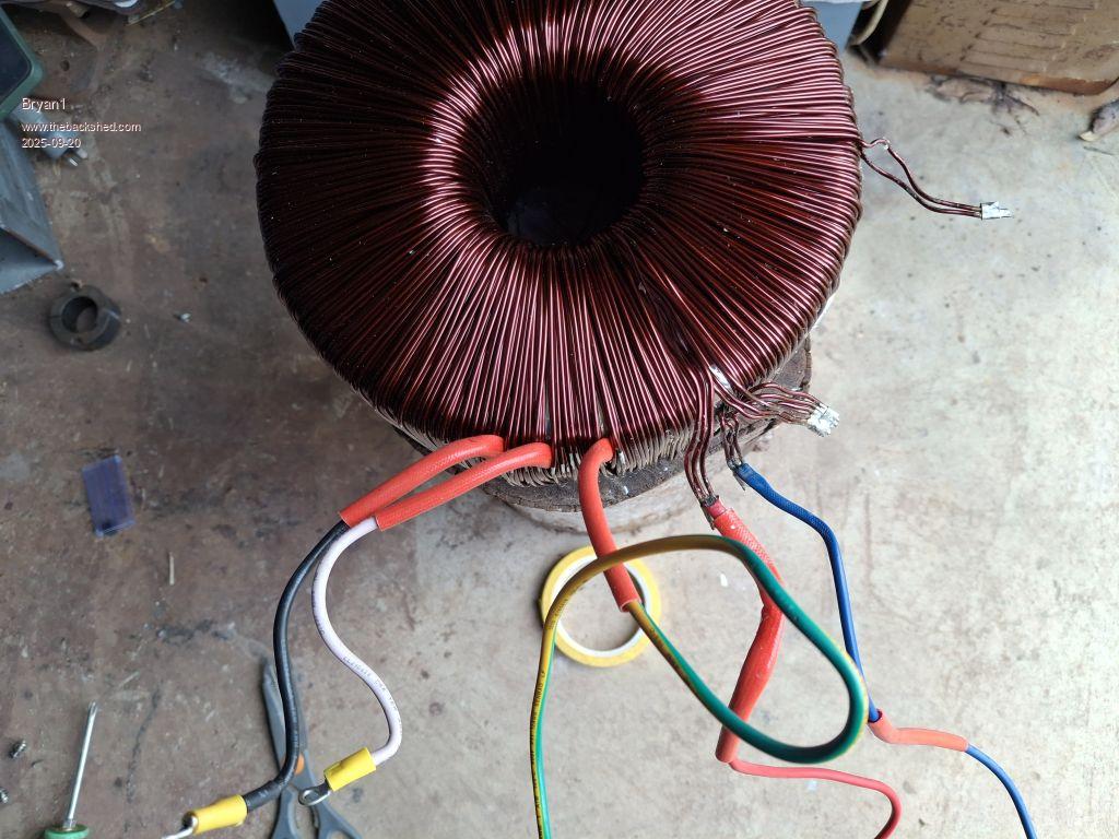 So now the task of unwinding the 250 volt wire and will update pic's as I go. Regards Bryan Edit: Well so far unwound about 60 metres and the tummy bones are singing out stating feed me So to be continued in the morning Edited 2025-09-20 17:33 by Bryan1 |
||||
| The Back Shed's forum code is written, and hosted, in Australia. | © JAQ Software 2026 |
