
|
|
Forum Index : Microcontroller and PC projects : Huntron tracker on LCD backpack
| Page 1 of 3 |
|||||
| Author | Message | ||||
| Volhout Guru Joined: 05/03/2018 Location: NetherlandsPosts: 5994 |
In my previous job the company I worked for had HAMEG oscilloscopes that had a component check feature. Very helpful if you want a quick analysis of a defective printed circuit board. This component check feature has been at the basis of the well known "Huntron Tracker". My current employer did not have these HAMEG oscilloscopes, or Huntron Trackers. Since the technology behind it is very simple, I used a standard oscilloscope, a function generator, and a 10k resistor to achieve similar functionality. In my mind an idea formed to build this functionality with a micromite and an LCD screen. First I thought about the LCD backpack. Then, at matherps advice, I ordered a ArmiteF4 and screen, but had bad luck these did not work. Back to the Back...pack. Drawing some schematics, and prototyping resulted in this 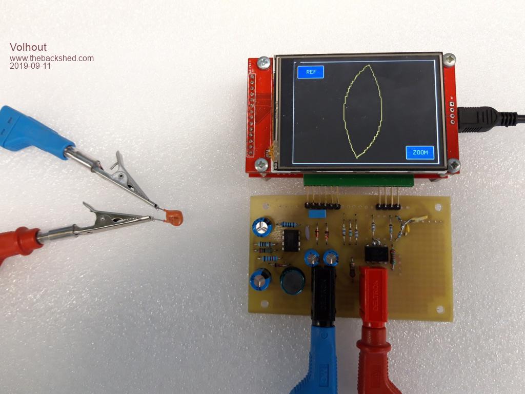 The small PCB holds basically 2 circuits On the left side is a convertor that makes +/-16V to power the amplifier (the test voltage is +/- 12V). On the right side is a PWM lowpass filter, and an amplifier that amplifies the 3.3V signal to +/- 14V. The micromite ADC is used to measure the voltage back. Software is not ready yet (ZOOM is not implemented), but I thought I should share the current status with you. ' For ILI9341 LCD backpack on 28 pin MX170 ' Uses pin 24 as analog input ' Uses pin 4 as pwm output Option explicit '------------------------------ init ------------------------ init: �'PIC32MX170 initialisation �CPU 48 � � � � � � �'max speed �SetPin 24,ain � � � 'voltage input �PWM 1,120000,50 � � 'set PWM to 0Vdc �' Declare variables �' for user interface �Dim integer show_ref=0,zoom=0,xt,yt �' generic �Dim integer h,i,j,adc �' display waveform �Dim integer x0,y0,x(200,2),y(200,2),pw(200) �'Declare constants �Dim integer huntron = 1 � � �' V/I graph=1, V/V graph=0 �Dim integer ADC_gain=30 � � � ' 100/3.3 = scale ADC from 0-100 �' initialize pwm waveform �' these values are directly written to the PWM that ranges �' from 0(%) to 100(%), waveform is triange �For i=1 To 100 � �pw(i) = 100 - i �Next �For i=101 To 200 � �pw(i) = i - 100 �Next �' initialize screen �draw_window �'enable touch �SetPin 15, INTL, Touch_Int '------------------------------ MAIN ------------------------ main: �Timer = 0 �'real time loop �For i= 1 To 200 � � � � � � � �' current pointer � �j=i-1: If j=0 Then j=200 � � ' last pointer � �'output pwm new value � �PWM 1,120000,pw(i) � � � � � ' set the output voltage � �'erase old line segment � �Line x0,y0,x(i,1),y(i,1),1,RGB(black) � �'write REF memory line on screen � �If show_ref=1 Then � � �Line x(j,2),y(j,2),x(i,2),y(i,2),,RGB(red) � �End If � �'keep old coordinates for next erase segment � �x0=x(i,1):y0=y(i,1) � �'write new segement after measuring � �adc=Pin(24)*ADC_gain � � �' measure � �If huntron Then � � �y(i,1)=(adc - pw(i) + 50) * MM.VRes / 100 � � �x(i,1)= adc * MM.HRes / 100 � �Else � � �x(i,1)=(pw(i) * MM.HRes) / 100 � � �y(i,1)=(100 - adc) * MM.VRes / 100 � �End If � �Line x(j,1),y(j,1),x(i,1),y(i,1),1,RGB(yellow) �Next i �Print Timer � � � � � � � 'loop timer to check performance �GoTo main '--------------------------- SUBS --------------------------- Sub Touch_Int �xt=Touch(x):yt=Touch(y) �'check for REF button �If xt<70 And yt<40 Then � �If show_ref=0 Then � � �For h=1 To 200 � � � � �'copy live to REF line � � � �y(h,2)=y(h,1) � � � �x(h,2)=x(h,1) � � �Next � � �show_ref=1 � � � � � � � � � � 'display ref line � � �RBox 10,10,60,30,2,RGB(white),RGB(red) � � �Text 30,18,"REF",,,,RGB(white),RGB(red) � �Else � � �draw_window � � � � � � 'start with blank screen (easy erase) � � �show_ref=0 � � � � � � � � � � 'do not draw REF line � � �'RBox 10,10,60,30,2,RGB(white),RGB(blue) � � �'Text 30,18,"REF",,,,RGB(white),RGB(blue) � �End If �End If �'check for ZOOM button �If xt>265 And yt>208 Then zoom = 1 - zoom � � � 'zoom �'If xt>265 And yt>208 Then huntron=1-huntron � �'huntron mode �Print "show_ref,zoom,huntron",show_ref,zoom,huntron �Pause 200 � � � � � � � � 'prevent double touch End Sub Sub draw_window �'clear screen �CLS �'draw window �Line 1,1,1,240,,RGB(white) �Line 1,240,320,240,,RGB(white) �Line 320,240,320,1,,RGB(white) �Line 320,1,1,1,,RGB(white) �'draw buttons �RBox 10,10,60,30,2,RGB(white),RGB(blue) �Text 30,18,"REF",,,,RGB(white),RGB(blue) �RBox 250,200,60,30,2,RGB(white),RGB(blue) �Text 265,208,"ZOOM",,,,RGB(white),RGB(blue) End Sub There is one coding issue to solve: because I scaled everything from 0-100 (just to make it easy to interchange voltages and currents and pwm, there is a rounding artifact that can be observed (see also photo). It is basically a disadvantage of not having access to binary values in ADC registers and PWM registers. the "REF" function stores the current waveform and shows it in red, so it is easy to compare. Currently (with all functionality) the refresh rate on the display is 400miliseconds (2.5x per second). Edited 2019-09-11 20:58 by Volhout PicomiteVGA PETSCII ROBOTS |
||||
| lizby Guru Joined: 17/05/2016 Location: United StatesPosts: 3811 |
Terrific job 3 questions--easy to harder Did you make up your alligator-clip to probe thingy, or do you have a link to where it may be bought What problems did you encounter with the F4 and LCD? Can you publish a schematic and do you intend to make a PCB? PicoMite, Armmite F4, SensorKits, MMBasic Hardware, Games, etc. on FOTS |
||||
| Volhout Guru Joined: 05/03/2018 Location: NetherlandsPosts: 5994 |
hi lizby, 1/ There is no probe, It is a component with wires. 2/ The F4 did not connect through USB after mmbasic was programmed. Programming went well though. Others have experienced the same, but it is different between units. Some do connect after few tries. Mine doesn't. 3/ Schematics and final code will come when I am satisfied with the performance. Although it doesn't look like it, the photo shows a PCB (single sided). Volhout PicomiteVGA PETSCII ROBOTS |
||||
| lizby Guru Joined: 17/05/2016 Location: United StatesPosts: 3811 |
Thanks. How are your alligator clip thingys/wires constructed? PicoMite, Armmite F4, SensorKits, MMBasic Hardware, Games, etc. on FOTS |
||||
| CaptainBoing Guru Joined: 07/09/2016 Location: United KingdomPosts: 2171 |
you can disable the onboard USB and connect to the console UART directly (as you would a "normal" uMite) if that helps |
||||
| gadgetjack Senior Member Joined: 15/07/2016 Location: United StatesPosts: 233 |
Following this with much interest.....  |
||||
| lizby Guru Joined: 17/05/2016 Location: United StatesPosts: 3811 |
With " SetPin 15,ain � � � 'voltage input", this runs on my F4. Of course, I don't have the associated hardware, so only the buttons appear on the screen. Regarding the F4, sorry to hear that you couldn't get it to work. I had problems of unknown origin with the first one I tried (flashed ok, wouldn't provide ">" prompt), but it and 5 others have worked for me since (I swapped the mini-usb cable for some, but not for others). An F4 mmbasic version with OPTION SERIAL CONSOLE ON (COM1) is on page 3 of the "programming the firmware" thread here: 2019-05-25_213711_ArmmiteF4.zip I don't remember whether there is a later version with COM1 active as console. Edited 2019-09-12 07:32 by lizby PicoMite, Armmite F4, SensorKits, MMBasic Hardware, Games, etc. on FOTS |
||||
| BrianP Senior Member Joined: 30/03/2017 Location: AustraliaPosts: 292 |
I have some similar things here - they came as part of a multimeter test lead set. Jaycar or Altronics should still have... B |
||||
| Volhout Guru Joined: 05/03/2018 Location: NetherlandsPosts: 5994 |
A small update: Have updated the code a bit, rather satisfied now (appart from the zoom that is still missing). 1/ speed (3 refresh / sec) although not a lot can be achieved, I made following changes to minimize the refresh time a/ use multiple single dimension arrays, that is faster than multi dimensional arrays in stead of Dim x(200,2) use Dim x(200), xr(200) b/ remove all comments from the loop (in a compiler that does not help, but the interpreter has to skip all the comment lines) c/ move calculations out of the loop whenever possible 2/ resolution everything scales to 1000 now, in stead of 100. That is clearly visible in the waveform (see picture). Next I will implement the "zoom", and then update the layout and schematics (zoom has hardware impact). 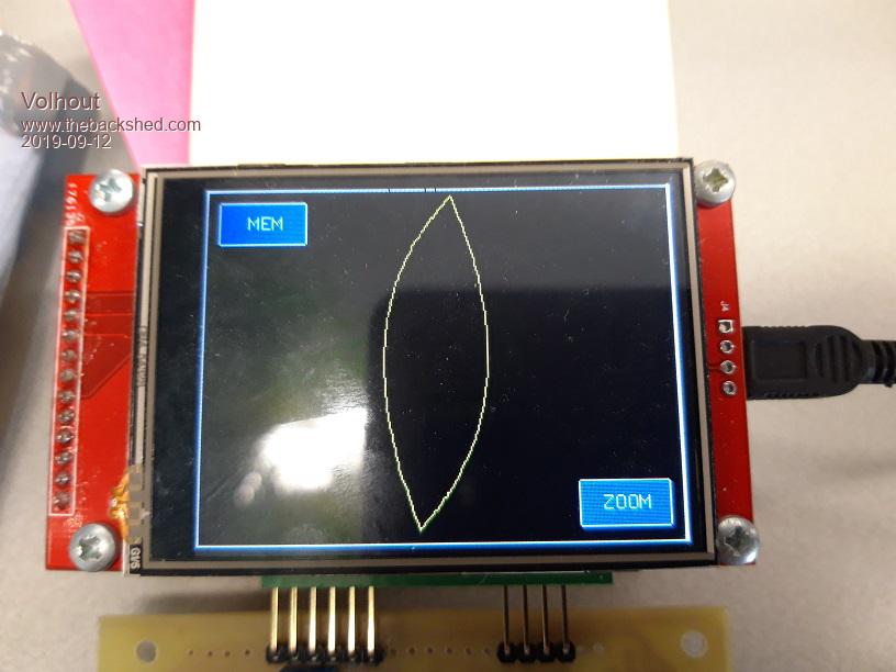 Edited 2019-09-12 17:27 by Volhout PicomiteVGA PETSCII ROBOTS |
||||
| Volhout Guru Joined: 05/03/2018 Location: NetherlandsPosts: 5994 |
I am finally satisfied with the performance. The resolution and number of sampes per refresh are variable in this code, and with the current settings it is workable on an MX170. I get 8 fps (frames per second, in this case waveform refreshes per second). For those who want to experiment, constants are defined in beginning of the program. Implemented the hardware zoom, the software zoom, and memory. The code should be compatible with other screen resolutions since I used MM.HRES and MM.VRES in the relevant scaling. Have no option to try it myself though. Attached photo gives an impression of the basic functions, measuring a 4.3V Zener diode, and comparing it with a different Zener diode. In normal mode the test voltage varies between +13V and -13V (so you could even test 12V zeners) In zoom mode the range is +6.5V to -6.5V (half) to get better resolution for diodes and low voltage zeners. I had some HW bugs in the layout, in the next posts I will add readable schematics, an updated layout (graphics only, it is not made in a CAD system) and code. 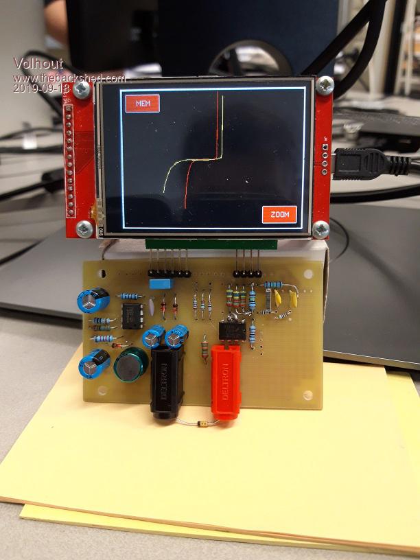 PicomiteVGA PETSCII ROBOTS |
||||
TassyJim Guru Joined: 07/08/2011 Location: AustraliaPosts: 6546 |
I am looking forward to building one to have a play with. I used something similar a long time ago in college but haven't used one in 'real life' Jim VK7JH MMedit |
||||
| Volhout Guru Joined: 05/03/2018 Location: NetherlandsPosts: 5994 |
This is the current software, version V0.9 The only thing I am currently unsure about is the calibrate at poweron. The analog HW is designed to work with E12 range resistors. To match all the tolerances in the analog circuits, I run an automatic calibration at powerup. Basically it calculates the ADC offset and gain from 2 measurements in each range. This works fine, as long as you don't have the input pins unconnected�.. and goes totally wrong if not. I may in future release perform a calibration ONCE, and store the values somewhere. '+-------------------------------------------------------------+ '| | '| BACKPACK TRACKER | '| | '| 09-2019 Volhout @ TheBackShed.com | '+-------------------------------------------------------------+ ' Curve tracer type huntron tracker ' For ILI9341 LCD backpack on 28 pin MX170 ' Uses pin 24 as analog input ' Uses pin 4 as pwm output ' Uses pin 9 and 10 to set amplifier gain ' all values scaled to 'resolution' ' there are 'samples' measurements per period '------------------------- Version History ------------------ ' V00 Proof of concept with 640 samples 100 resolution ' V01 Increase resolution to 1000, decrease samples to 200 ' V02 Implemented touch for REF and ZOOM buttons, REF added ' V03 Optimized main loop from 400msec to 300msec ' V04 Implemented support for HW zoom ' V05 Zoom implemented in SW ' V06 Restructure code to support samples and resolution as constants ' V07 Tune performance on MX170 ( 8 frames / second ) ' V08 Improved code for readability, remove obsolete DIM's ' V09 Screen resolution independent (untested), added HW calibrate ' at poweron. '------------------------------ init ------------------------ Option explicit init: 'PIC32MX170 initialisation CPU 48 ' max speed SetPin 24,ain ' voltage input PWM 1,120000,50 ' set PWM to 0Vdc amp_high_gain ' set amplifier gain ' Define samples each scan Const samples = 64 Const resolution = 1000 ' Declare variables ------------------------------------------------- ' Declare defaults for scaling ADC to 'resolution', these values ' are fine tuned in calibration (at powerup) Dim integer lowgain=resolution/3.3, highgain=2*lowgain Dim gain=lowgain Dim integer lowoffset=0, highoffset=-resolution/2 Dim offset=lowoffset ' for user interface, xt/yt are touch coordinates Dim integer xt,yt ' generic i,j,h are counters, ADC is scaled adc value, adc10 and adc90 ' are used in calibration Dim integer i,j,h,ADC Dim float adc10,adc90 ' display waveform, x/y are measured waveform, xr/yr are memory reference Dim integer x0,y0,x(samples),y(samples),xr(samples),yr(samples) ' init coordinates with values that fit the screen For i=1 To samples xr(i)=MM.HRes-3:yr(i)=MM.VRes/2:x(i)=MM.HRes-3:y(i)=MM.VRes/2 Next i x0=MM.HRes-3:y0=MM.VRes/2 ' generate waveform, pw = pwm value, pc = pwm value scaled to 'resolution' Dim pw(samples), pc(samples) ' fill waveform with triange wave 0...100% For i=1 To samples / 2 pw(i) = 100 - ( 200 / samples ) * i pc(i) = resolution * pw(i) / 100 pw(i + samples / 2) = ( 200 / samples ) * i pc(i + samples / 2) = resolution * pw(i + samples / 2) / 100 Next ' graphics scaling to resolution Dim float Vstep = MM.VRes / resolution, Hstep = MM.HRes / resolution Dim center = resolution / 2 ' buttons and line colors Dim integer membuttoncolor = RGB(blue), zoombuttoncolor = RGB(blue) Dim integer memcolor = RGB(black), linecolor = RGB(yellow) 'debug Memory ' initialize screen draw_window ' enable touch SetPin 15, INTL, Touch_Int ' calibrate analog circuits calibrate '------------------------------ MAIN ------------------------ main: ' all comments removed from main loop to speed it up ' cycle through all pwm values using pointers i (actual) and j (last) ' erase last segment ' allways draw memory line, but color decides if it is visible ' draw memory line first so actual overwrites memory ' measure input value ' recalculate new segment (huntron method) ' draw new segement Do 'Timer = 0 For i = 1 To samples j = i - 1 : If j = 0 Then j = samples PWM 1,120000,pw(i) Line x0,y0,x(i),y(i),1,0 Line xr(j),yr(j),xr(i),yr(i),1,memcolor x0 = x(i) : y0 = y(i) ADC=(Pin(24) * gain) + offset y(i)=(ADC - pc(i) + center) * Vstep x(i)= ADC * Hstep Line x(j),y(j),x(i),y(i),1,linecolor Next i 'Print Timer Loop '--------------------------- SUBS --------------------------- Sub Touch_Int xt = Touch(x) : yt = Touch(y) 'check for MEM button if we should display memory If xt < ( MM.HRes / 4 ) And yt < ( MM.VRes / 4 ) Then If memcolor = RGB(black) Then For h = 1 To samples 'copy live to REF line yr(h) = y(h) xr(h) = x(h) Next memcolor = RGB(red) membuttoncolor = RGB(red) Else memcolor = RGB(black) membuttoncolor = RGB(Blue) End If RBox 10,10,60,30,2,RGB(white),membuttoncolor Text 30,18,"MEM",,,,RGB(white),membuttoncolor End If 'check for ZOOM button to see if we should zoom in If xt > (3 * MM.HRes / 4 ) And yt > (3 * MM.VRes / 4) Then If zoombuttoncolor = RGB(blue) Then zoombuttoncolor = RGB(red) adc_high_gain amp_low_gain Else zoombuttoncolor = RGB(Blue) adc_low_gain amp_high_gain End If RBox MM.HRes-70,MM.VRes-40,60,30,2,RGB(white),zoombuttoncolor Text MM.HRes-55,MM.VRes-32,"ZOOM",,,,RGB(white),zoombuttoncolor End If Pause 300 'prevent double touch End Sub Sub amp_high_gain SetPin 9,dout : Pin(9)=0 SetPin 10,dout : Pin(10)=1 End Sub Sub amp_low_gain SetPin 9,din SetPin 10,din End Sub Sub adc_high_gain gain = highgain offset = highoffset End Sub Sub adc_low_gain gain = lowgain offset = lowoffset End Sub Sub draw_window 'clear screen CLS 'draw window Line 1,1,1,MM.VRes-2,3,RGB(white) Line 1,MM.VRes-2,MM.HRes-2,MM.VRes-2,3,RGB(white) Line MM.HRes-2,MM.VRes-2,MM.HRes-2,1,3,RGB(white) Line MM.HRes-2,1,1,1,3,RGB(white) 'draw buttons RBox 10,10,60,30,2,RGB(white),membuttoncolor Text 30,18,"MEM",,,,RGB(white),membuttoncolor RBox MM.HRes-70,MM.VRes-40,60,30,2,RGB(white),zoombuttoncolor Text MM.HRes-55,MM.VRes-32,"ZOOM",,,,RGB(white),zoombuttoncolor End Sub Sub calibrate 'calibrate standard mode ------------ amp_high_gain adc_low_gain 'measure 10% and 90% points PWM 1,120000,10 Pause 1 adc10 = Pin(24) PWM 1,120000,90 Pause 1 adc90 = Pin(24) 'calculate ADC low gain and offset lowgain = 80 * resolution / (100 * (adc90 - adc10)) lowoffset = - lowgain * (adc10 - ((adc90 - adc10)/8)) 'Print lowgain , lowoffset 'calibrate zoom mode -------------- amp_low_gain adc_high_gain 'measure 10% and 90% values PWM 1,120000,10 Pause 1 adc10 = Pin(24) PWM 1,120000,90 Pause 1 adc90 = Pin(24) 'calculate ADC high gain and offset highgain = 80 * resolution / (100 * (adc90 - adc10)) highoffset = - highgain * (adc10 - ((adc90 - adc10)/8)) 'Print highgain , highoffset 'back to standard mode amp_high_gain adc_low_gain End Sub PicomiteVGA PETSCII ROBOTS |
||||
| CaptainBoing Guru Joined: 07/09/2016 Location: United KingdomPosts: 2171 |
very nice! |
||||
| Paul_L Guru Joined: 03/03/2016 Location: United StatesPosts: 769 |
Many decades ago we had a couple dozen Huntron Trackers in the electronic shops at Pan Am. They were EXTREMELY useful devices which saved a lot of time in troubleshooting. This looks like a really useful gadget to have. I recommend it to everyone here! Thanks Harm! Paul in NY |
||||
| Volhout Guru Joined: 05/03/2018 Location: NetherlandsPosts: 5994 |
You must have been waiting eagerly for this.... Finally the schematics of the backpack tracker. Honestly, the prototype board was drawn on a sheet of paper, and the PCB was made using the toner transfer method from a simple SPRINT (draw lines and pads) program. Since I had not used CAD packages for some 20 years (yeah...as a manager you don't do the fun stuff) , I am going through the learning curve again with KICAD. This is the schematics, I have done the placement, next week I will do the routing again....in KICAD. I'll update this thread when I am satisfied with the routing and silkscreen.... Volhout Edit: oops, R15 must be 47K, R16 must be 3.9K If some wonder about the choice for a LM741: it has maximum voltage range of +/- 20V. More modern opamps limit to +/- 15V. Edited 2019-09-20 16:57 by Volhout PicomiteVGA PETSCII ROBOTS |
||||
| panky Guru Joined: 02/10/2012 Location: AustraliaPosts: 1132 |
Valhout, I don't understand the configuration of R3,R4, R6 and R7? As shown, I can not see how there is any difference between changing either of the gain lines from the MM? If you get the time (and the inclination  , could you perhaps give a brief Theory of Operation of your circuit with reference to the software. , could you perhaps give a brief Theory of Operation of your circuit with reference to the software.This is a great idea and I am well on the way to a port to the E100 with a 9" LCD display using the MM+ GUI commands. panky ... almost all of the Maximites, the MicromMites, the MM Extremes, the ArmMites, the PicoMite and loving it! |
||||
| TassyJim Guru Joined: 07/08/2011 Location: AustraliaPosts: 6546 |
The two gain pins are switched to high Z inputs for low gain setting so they are effectively taken out of play. For high gain, they are tied to 3.3V and GND putting them in parallel with R6 and R8, changing the feedback ratio. I too would like a run down on the operation. this might be a starting place: http://www.huntron.com/sales-support/pdf/ASA-paper-extract.pdf Jim Edited 2019-09-20 17:31 by TassyJim VK7JH MMedit |
||||
| Volhout Guru Joined: 05/03/2018 Location: NetherlandsPosts: 5994 |
I'll explain a bit about the operation. TassyJim's article more or less sums it up, but I'll add this bit. The BACKPACK_TRACKER is a measuring device for impedance. It applies a voltage to a component and measures the current. By varying the voltage, and measuring the current at each change you can detect complex impedances (inductors/capacitors) and non linear impedances (semi conductors). Graphical representation of voltage and current makes instant recognition possible (humans are very visually oriented). But audible representation is also viable. BACKPACK TRACKER works visual. A device like this is also referred to as a curve tracer. The word TRACKER is from following a trace. The only difference between the theoretical description above, is that the MX170 on the LCD backpack has only 1 ADC free. Therefore measuring voltage (ADC1) and current (ADC2) is not possible. The trick is to use 1 ADC that measures a voltage that is a combination from voltage and current, and subtrackt the theoretical voltage from it to. Residual is the current. That is done in these 2 lines. �y(i)=(ADC - pc(i) + center) * Vstep �x(i)= ADC * Hstep Vertical (y(i)) plotted is the measured voltage - theoretical voltage = current Horizontal (x(i)) plotted is the measured voltage If you look at the schematics, the PWM signal (120kHz, 0V/3.3V) is filtered to a DC voltage. By varying the PWM, we can change the DC voltage into a low frequency AC signal, in our case a triangle wave. The amplifier U2 changes the 0V and 3.3V levels to -14V and +14V. Through impedance R16 this is applied to the test probe. Below plot shows the PWM signal and triange waveform at test pins in normal mode and 64 samples per frame. 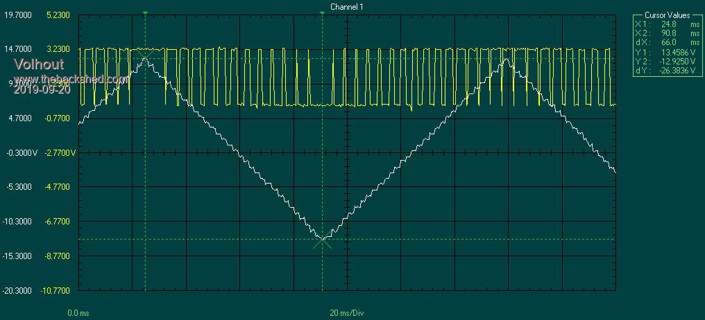 At each step in the waveform a sample is taken, and drawn on the screen. Around 500 vectors per second are calculated, and a 1500 drawn (1 erase old, 1 draw memory line, 1 draw actual line). That happens in this section. � � Line x0,y0,x(i),y(i),1,0 � � � � � � � � �' erase � � �Line xr(j),yr(j),xr(i),yr(i),1,memcolor � ' memory line � � x0 = x(i) : y0 = y(i) � � ADC=(Pin(24) * gain) + offset � � y(i)=(ADC - pc(i) + center) * Vstep � � x(i)= ADC * Hstep � � Line x(j),y(j),x(i),y(i),1,linecolor � � �' draw actual vector The oscilloscope picture yellow line does not represent the actual PWM waveform, since the picture lacks resolution. Below is a detail of the lowest point in the triange waveform (zoomed in hunderds of times). 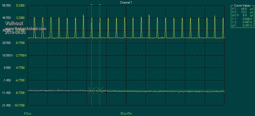 The memory function, simply copies the current waveform to a memory register (xr(i) and yr(i)) and changes the color of the memory line to red. That makes it visible. The default color was black. The number of samples in a frame can be changed in the code. That has impact in the waveform (more steps is finer waveform) but slows down the refresh rate of the screen. Waveform with 200 samples per frame is shown here. 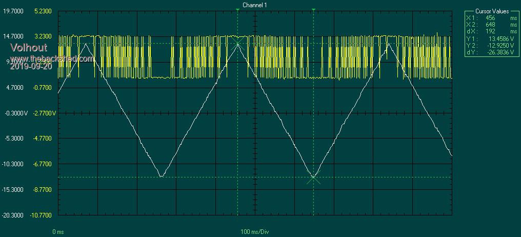 ZOOM Normally zooming would just be done graphically, but we are tied into MMBasic and the MX170, with only 100 possible different PWM setting. By zooming in we would only have 50 or less. Therefore a hardware trick is needed. The amplifier has maximum gain in normal mode. The maximum gain is achieved when IO pins 9 and 10 are set to output (low impedance) and pin 9 is 0, pin 10 is 1.In fact parallelling R3, R4 and R6 R7 R8. When zoom is selected, the amplifier makes a lower output voltage (lower gain), but the PWM remains at full range (100 steps). The lower gain is achieved by making pins 9 and 10 high impedance (input), and the gain is determined only by R6,R7,R8 and R12. R6 and R7 parallel are 91K, so if you can get E24 values, you don't need 2 resistors. Graphical zoom can be used for the ADC. No hardware needed, since the ADC is 12 bits (4096 steps). With 200% zoom still has a resolution of 2048, far exceeding the resolution on the PWM. The lower gain waveform is shown below. 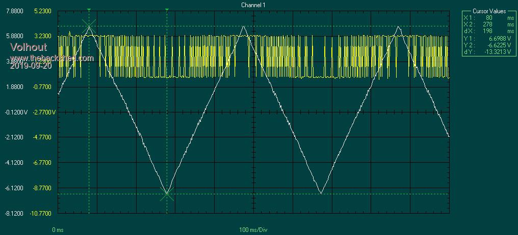 Edited 2019-09-20 19:30 by Volhout PicomiteVGA PETSCII ROBOTS |
||||
| JohnS Guru Joined: 18/11/2011 Location: United KingdomPosts: 4352 |
Don't those voltages damage any components? John |
||||
| Volhout Guru Joined: 05/03/2018 Location: NetherlandsPosts: 5994 |
Hi JohnS, The 14V is current limited (3mA). Typical circuits won't get damaged by it, but I would definitely not advise to probe inside a 10GHz low noise amplifier or 100GHz spectrum analyzer input stage (there are FET's in there that do not have protection diodes build in to achieve better RF performance). But the typical circuits we deal with are fine with these signals. Volhout PicomiteVGA PETSCII ROBOTS |
||||
| Page 1 of 3 |
|||||
| The Back Shed's forum code is written, and hosted, in Australia. | © JAQ Software 2026 |
