Notice. New forum software under development. It's going to miss a few functions and look a bit ugly for a while, but I'm working on it full time now as the old forum was too unstable. Couple days, all good. If you notice any issues, please contact me.
brucedownunder2 Guru Joined: 14/09/2005 Location: AustraliaPosts: 1548
Posted: 02:43am 25 Feb 2019
Copy link to clipboard
Print this post
Hi Mark..
You'll win ,, I know
been there, done that ,,, sh*tte happens.
all the best, mate
BruceBushboy
johnmc Senior Member Joined: 21/01/2011 Location: AustraliaPosts: 282
Posted: 03:38am 25 Feb 2019
Copy link to clipboard
Print this post
Good Day Mark, Not much I can offer, but Know the frustration keep us up to date cheers johnjohnmc
renewableMark Guru Joined: 09/12/2017 Location: AustraliaPosts: 1678
Posted: 03:41am 25 Feb 2019
Copy link to clipboard
Print this post
Look on the bright side boys, it keeps the mosfet makers happy.Cheers Caveman Mark Off grid eastern Melb
wiseguy Guru Joined: 21/06/2018 Location: AustraliaPosts: 1017
Posted: 03:11pm 25 Feb 2019
Copy link to clipboard
Print this post
Sorry to hear the crappy result Mark. I wouldn't expect a bit more secondary capacitance to make it go bang. A few older style fluros would have more uF than that. Sure the efficiency would fall a tad and circulating currents increase.
Are you using the original choke or a newly wound (same as original) choke?
Is it possible that the crappy waveform may have always been there but if you werent using the air con at the time you were unaware of it as it looked ok on the CRO ?
Before Klaus chimes in - no I dont have a working inverter yet - yes its still theory - but I'm putting it all to good use, busy helping others blow up their inverters to work out what not to do with mine
Lastly Mark what was the load at the time it went bang with the extra 2uF ?
PS sorry for my poor attempt at humour.......
Edited by wiseguy 2019-02-27If at first you dont succeed, I suggest you avoid sky diving.... Cheers Mike
renewableMark Guru Joined: 09/12/2017 Location: AustraliaPosts: 1678
Posted: 08:07pm 25 Feb 2019
Copy link to clipboard
Print this post
Both chokes were the same that have been in service for 6 months of smooth sailing running the house. I checked and increased the gap (3mm) on the ferrite, but did nothing to the iron choke.
The issue wasn't present before as I was previously running the Air con vigorously without any of the symptoms. When the Air c ran with the crap wave form it surged and you could hear my printer at my desk hum and the lights dimmed and brightened, so it was a very clear different event that was happening.
Load was zero when it went bang, just turned it on and the hum got louder and louder, like pressure building up than an almighty bang like I have never seen before. Entire garage was filled with smoke. It was a bloody ripper, pity I didn't get it on camera!
All this started when I used the new torroid to see how the screened one went. It appears the frequency was miles off the ideal 75hz.
Because I used welding wire on the toroid it was easy to unwind then remove screen and put primary back on. I should have just gone back to the old toroid, but I wanted to make two units so one could be kept as a spare.
So next step is to use the old toroid and rebuild the board. At least I know 6uf is tuned to 75hz on that one.
Hopefully Tony does a detailed thread on how to get that tuning correct as I can't remember how he did it.Edited by renewableMark 2019-02-27Cheers Caveman Mark Off grid eastern Melb
Warpspeed Guru Joined: 09/08/2007 Location: AustraliaPosts: 4406
Posted: 09:21pm 25 Feb 2019
Copy link to clipboard
Print this post
All the clues are falling into line.
Mark, you mentioned that the new toroid has even lower idling current than the original. To me that suggests more turns, better steel, or more steel in the core or a combination of the above. It also means it almost certainly now has significantly higher inductance, which is all good.
Revlac also mentioned earlier that both the choke and the transformer need to be actually tested to ENSURE that they are working properly. Both the choke air gap and the 75Hz resonating capacitance need to tweaked, and the 75 Hz is the more critical parameter to adjust.
Now it sounds logical that external load capacitances such as motor starting and fluorescent light capacitors would badly detune the transformer, and that might be true. But that detuning will also coincide with some significant additional inverter loading.
With very light load or zero load the transformer and its resonating capacitor will be working alone. Anything above 75 Hz is pretty safe, it just introduces wobbles onto the waveform. The sweet spot is exactly 75 Hz where the wobbles go away and the waveform is good.
Below 75 Hz gets dangerous, because its getting down close to 50Hz and we can get a very large destructive buildup of resonant energy in the transformer. Higher transformer inductance and extra added capacitance will do exactly that.
The large audible hum buildup, and then the *BANG* sounds just about right for this problem.
Fix the blown mosfets first and test it without any capacitors across the transformer. Make very sure all the gate drivers and gate resistors are o/k or it may blow up again. It should then run fine, but there will probably be a wobbly waveform.
Anyhow, when you get your new waveform generator with the digital frequency readout and digital frequency counter, we can get into the transformer tuning.
Various types available, but make sure it has an inbuilt frequency counter that can be driven from an external input. There will be an extra BMC connector on the front panel for external frequency input, as well as the waveformgnerator output BNC connector.
There is a much better and more accurate way to do all this, which involves making the transformer oscillate at its own self resonant frequency. But it requires a digital frequency counter to measure the oscillation frequency. Some of the better multimeters have an inbuilt frequency counter.
I will look into the oscillator method, its a very simple circuit called a Lambda oscillator using only a couple of transistors, but I need to actually test it myself before posting the method here.Cheers, �Tony.
wiseguy Guru Joined: 21/06/2018 Location: AustraliaPosts: 1017
Posted: 12:01am 26 Feb 2019
Copy link to clipboard
Print this post
Hi Tony hoping you would chime in soon, there might need to be further clarification I think.
A page or two ago I understood Mark had put the unshielded (original?) toroid back in the inverter and it still had a fairly crappy waveform. Edit - I admit it I am getting a bit confused as to what exactly the setup was when it went bang.
So that begs the question if he was back at the original setup with original toroid that did work well before, what changed to cause the detuning that you suspect - not being argumentive just trying to get all the facts correct to ensure we head off in the right direction.
I did some back of the envelope calculations last night with 9uf translated back to the primary (72uF) and say 200uH of choke inductance, the resonance was of the order of 1kHz (when it went bang). My suggested 12uH might have higher ripple & work harder but the resonance for the same setup was around 5kHz. Over to you Tony, what does it all mean, is any of that relevant to the tuning & performance. What happens when we add reactive loads to the inverter do we run a risk of detuning it, or is this mainly relevant to no or light loads?Edited by wiseguy 2019-02-27If at first you dont succeed, I suggest you avoid sky diving.... Cheers Mike
renewableMark Guru Joined: 09/12/2017 Location: AustraliaPosts: 1678
Posted: 12:59am 26 Feb 2019
Copy link to clipboard
Print this post
Mike, I took the shield off just to see if that was causing the problem. that was my reference to going back to unshielded. it wasnt the old toroid. Tony, what was the method you did with my last toroid to tune that?Cheers Caveman Mark Off grid eastern Melb
Warpspeed Guru Joined: 09/08/2007 Location: AustraliaPosts: 4406
Posted: 03:32am 26 Feb 2019
Copy link to clipboard
Print this post
Mike, All this forms rather a long story, but there is also a lot that cannot really be defined terribly well when analyzing all this such as the nature of the load (?).
I will try to keep this a brief as I can, so forgive me if I skate quickly over some of the details.
What comes out of our switching bridge looking at it in the frequency domain is a lot of energy at 50Hz (which we want) plus some much smaller harmonics of 50Hz due to harmonic distortion. There is also a lot of energy at 23Khz (that we are trying to block) and a vast number of harmonics of multiples of 23 Khz with considerable energy. There should be little or no energy between about 500Hz and 23 Khz.
To separate out the 50Hz from the 23Khz we use a low pass filter consisting of our series choke and a shunt capacitor down to ground, or to the other side of the bridge. That shunt capacitor may be a real capacitor across the primary of the transformer, or it might be a real capacitor across the transformer secondary reflected back into the primary.
Its usually placed across the primary on high voltage grid tie inverters, because its more effective there. On low voltage off grid inverters its always across the secondary. The reason being the very high ripple current rating required in the primary of a low voltage inverter requires a much larger and much more expensive component. So we put it across the secondary instead.
Anyhow that choke and its shunting capacitance forms a low pass filter with a cutoff frequency somewhere between 50Hz and 23 Khz. We would normally place it well clear of either frequency and it might ideally end up about 1Khz.
Why 1Khz ? Well 1Khz is x20 50Hz and its about 1/20 of 20Khz a typical PWM switching frequency. But its not critical. If we make the filter cut off frequency much lower than 1Khz we start to attenuate our 50Hz. If we make it much higher than 1Khz we lose attenuation of our PWM frequency that we are trying to get rid of.
That should work out fine, because there is another issue. The choke and the shunt capacitor have a very low series impedance at 1Khz (or whatever the frequency is) but because there is no energy there, that does not cause a problem.
Now we come to our transformer, and that seriously complicates matters. The inductance of the winding that has the real shunt capacitor placed across it will form a parallel resonant circuit. Primary or secondary makes no difference, the effect will be the same.
This second resonance will most likely be lower than the choke 1Khz resonance, and it would probably not really matter unless it happens to fall on one of the harmonics of 50Hz. If that happens we are likely to see a higher frequency superimposed upon our 50Hz sine wave (our wobble frequency).
Its not really possible to get rid of this, but we can make it go lower in frequency by adding more capacitance across the transformer. If we can make it exactly 1.5 times the inverter frequency (75Hz) any resonant buildup in the transformer will be exactly out of phase the next cycle and will damp itself out.
Its possible to get rid of the wobbles that way without having any other serious effect. I did not invent this idea, its a "trick of the trade" and in fact a trick known to some of the grid tie inverter designers. I only discovered it by reverse engineering other people's designs. That is how designers spy on each other and learn why really good products work so well. That is what engineers do :o)
Mark,
Its just a case of driving the toroid secondary from a sine wave oscillator through a series resistor, and Looking at the waveform voltage across the transformer on an oscilloscope. Start with about a 4K7 series resistor, and with various values of capacitor across the transformer. There will be a definite peak in amplitude at one frequency.
A higher value resistor might give a slightly sharper peak, but the voltage will become much lower, and may get buried in 50Hz mains hum pickup. Making the series resistor much lower will give much higher voltage to measure, but the peaking effect becomes less defined. So try a few different resistor values something between 1K and 100K should work best.
Cheers, �Tony.
renewableMark Guru Joined: 09/12/2017 Location: AustraliaPosts: 1678
Posted: 02:02am 13 Mar 2019
Copy link to clipboard
Print this post
OK update, went back to old torroid (I don't think that was the problem though) Built a new power board. problem seems to have gone. No surging no flickering of lights. Sine wave looks fantastic with fridge, compressor, blow heater, elec oven, toaster, any of those and it's fine.
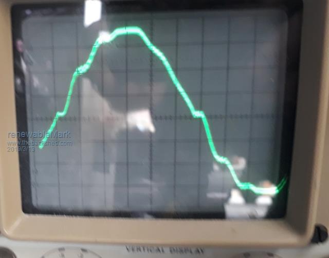
BUT, hair dryer on low it turns to crap, this has been talked about previously as a known cause for crap wave as it chops half the power with a diode.
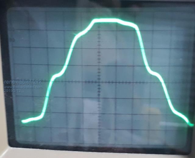
AND Air con on low settings. It's a very late model inverter AC unit, on full power sine is fine, but low fan settings it turns to crap, it varies in it's level of crap. Below are AC on low fan speed.
When the inverter was previously running fine it probably had this crap sine wave too, as I never checked it with the air con going. The air con appears to run fine, exactly the same as it does on mains power, so unless you checked with a cro you just wouldn't know. I also put the mains back on and tested the sine with the air con going and not going, sine was identical.
It appears that my machine simply doesn't have either the grunt or stability that the mains has.
So questions are, 1. will having such a terrible wave damage the AC unit and or other things in the house?
2. will messing with my chokes alleviate this?
I currently have the double stacked E70ferrites in series with a double stacked 3kw aerosharp iron core. (Warp tested the iron one to be well over 100A saturation) I don't quite understand how any more could help.
3. Would more, or bigger caps on the power board help?
Edited by renewableMark 2019-03-14Cheers Caveman Mark Off grid eastern Melb
Tinker Guru Joined: 07/11/2007 Location: AustraliaPosts: 1904
Posted: 09:55am 13 Mar 2019
Copy link to clipboard
Print this post
First thing I would try is without the ferrite choke, leave the other choke in. I have taken the ferrite chokes out of my inverters.
A tip for you Mark, turn the brightness on your oscilloscope down until you can barely see the trace, this produces a sharper picture.Klaus
renewableMark Guru Joined: 09/12/2017 Location: AustraliaPosts: 1678
Posted: 12:46am 14 Mar 2019
Copy link to clipboard
Print this post
Thanks Tinker I'll give that a go.
Since I have been having issues the house has been run on mains, last night after I got back from a job, the inverter got turned on again.... BANG blew all the fets.
This is starting to get demoralising .
On arriving home today the radio was giving me that terrible EMI again, so an effort was made to find it.
Turned out to be the Mad pwm controller.
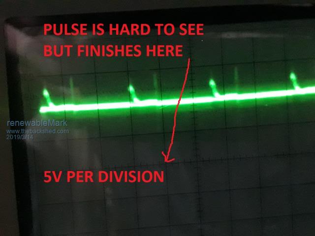
Then the inverter DC terminals got tested while this emi was being produced. This isn't the battery but the terminals that connect to the power board.
There is a stronger pulse and a lighter one which is hard to see on camera but very clear to the eye.
Would that be a concern?Cheers Caveman Mark Off grid eastern Melb
wiseguy Guru Joined: 21/06/2018 Location: AustraliaPosts: 1017
Posted: 02:01am 14 Mar 2019
Copy link to clipboard
Print this post
Tony, a belated thanks for the effort you put into your earlier reply - much appreciated. It all helps towards a better understanding, some of my biggest gains (and maybe some losses too?) I expect will be when I actually start playing with my own unit.If at first you dont succeed, I suggest you avoid sky diving.... Cheers Mike
johnmc Senior Member Joined: 21/01/2011 Location: AustraliaPosts: 282
Posted: 04:28am 14 Mar 2019
Copy link to clipboard
Print this post
Good day Mark Hang in there Mark the problem will be solved. I feel no random pulse should be allowed. Is the torriod transformer, the one that has been in service for months and is the power board Maddness one, with driver transistors?
What system do you use to start the inverter ? cheers johnjohnmc
renewableMark Guru Joined: 09/12/2017 Location: AustraliaPosts: 1678
Posted: 05:32am 14 Mar 2019
Copy link to clipboard
Print this post
Hi John, thanks for the well wishes, I bloody need them.
The toroid is the one that powered the unit for 6 trouble free months, power boards are the same Mad totem driven ones.
I was using the Mad control board, all tested fine, ran without caps, then replaced caps and ran ok (except for on air con the wave went a bit odd) Turned the machine off, then back on later in the day and BANG.
Ran out of 4008's now and waiting for another 100 to arrive.
I'm going to run the nano board now, I was using the Mad control board as I was familiar with it and I can test the pwm and square wave while just powering that up. I'll talk to Poida about test procedures for the nano control board.Cheers Caveman Mark Off grid eastern Melb
johnmc Senior Member Joined: 21/01/2011 Location: AustraliaPosts: 282
Posted: 07:29am 14 Mar 2019
Copy link to clipboard
Print this post
Mark had similar problems with inverter start up ( many times) The system I use now, and have had no more bangs smoke and general mayhem. step1 Make sure the inverter start switch is switched OFF step 2 With a 2.5mm2 jumper lead to charge the capacitors with a short flash to the capacitors supply so that they are fully charged there should be no more current flow to the charged capacitors if there continues to be current flow you have mostfet problems. step 3 turn on the inverter ( I believe mad uses a 80 amp dc circuit breaker to energize the capacitors). Cheers john johnmc
renewableMark Guru Joined: 09/12/2017 Location: AustraliaPosts: 1678
Posted: 08:44am 14 Mar 2019
Copy link to clipboard
Print this post
Yep I do all of that, but slightly different, I charge the caps via 2 33ohm resistors. My setup allows it to be fed by them via a breaker, then the main beaker takes over and the resistor breaker is opened. This also allows for resistance fed testing with no caps. When the voltage on the lcd from the control board reads 52v or more I trip the main breaker on. Never had a problem there. Just the start up is giving me problems now, it goes bang randomly. Very frustrating after doing the safe test with no caps, get a perfect sine all looking like there is no issue at all. Then fit caps, start it up and BANG! I was previously able to start and stop it as many times as desired, now it just wants to be totally random. Cheers Caveman Mark Off grid eastern Melb
Tinker Guru Joined: 07/11/2007 Location: AustraliaPosts: 1904
Posted: 09:05am 14 Mar 2019
Copy link to clipboard
Print this post
So, has all that soldering and unsoldering damaged the caps? Test them individually on your battery bank (not inside the inverter) via a slow charge resistor. Just a guess though.
When something runs satisfactorily for some time and you then do some modifications, causing it to go 'bang' then you need to analyze *each* step that you took to see where the gremlins could have got in.
It could be something silly like a solder blob in the wrong place or something replaced the wrong way round .Klaus
renewableMark Guru Joined: 09/12/2017 Location: AustraliaPosts: 1678
Posted: 09:14am 14 Mar 2019
Copy link to clipboard
Print this post
Nup, that was a brand new set. Got more spares than RS components here (except for 4008's).
Don't understand why it ran fine on resistance power then ok for a while with caps fitted then a random BANG when restarted. There was no error from previous either, it was just a plain shut down with on off switch. Upon cap charge and turn on it just went bang. No reason, makes me sus of the 8010.Cheers Caveman Mark Off grid eastern Melb
renewableMark Guru Joined: 09/12/2017 Location: AustraliaPosts: 1678
Posted: 11:04am 07 Apr 2019
Copy link to clipboard
Print this post
Well got me stuffed, Poida tested my Mad controller board and restarted it numerous times looking deep into it with his tricked up DSO.
Nothing wrong.....perfect. I suspected dodgey 8010's but nup... all of them were fine.
Something else is lurking in the shed. Cheers Caveman Mark Off grid eastern Melb


 .
.