Notice. New forum software under development. It's going to miss a few functions and look a bit ugly for a while, but I'm working on it full time now as the old forum was too unstable. Couple days, all good. If you notice any issues, please contact me.
renewableMark Guru Joined: 09/12/2017 Location: AustraliaPosts: 1678
Posted: 05:59am 28 Jan 2018
Copy link to clipboard
Print this post
Thanks guys, with the 0.067A clamp reading will that be the same with all three wired up or .067x3?Cheers Caveman Mark Off grid eastern Melb
Warpspeed Guru Joined: 09/08/2007 Location: AustraliaPosts: 4406
Posted: 06:12am 28 Jan 2018
Copy link to clipboard
Print this post
Yes, all three connected up will read exactly the same as just the one winding. So 16 watts for the transformer it is.
The circuit board and other electronics will draw a very few watts as well, but I think you might be on track for probably about 20 watts of idling power.Cheers, �Tony.
Madness Guru Joined: 08/10/2011 Location: AustraliaPosts: 2498
Posted: 06:37am 28 Jan 2018
Copy link to clipboard
Print this post
I may be wrong but I think it draws more power when running off the not quite as smooth SPWM, there is definitely more noise with it. It will be very interesting to see just how good it is when completed.
Keep the photos coming to Mark. There are only 10 types of people in the world: those who understand binary, and those who don't.
renewableMark Guru Joined: 09/12/2017 Location: AustraliaPosts: 1678
Posted: 06:43am 28 Jan 2018
Copy link to clipboard
Print this post
Nice, the extra few winding may have been a good idea.
Still strayed away from Oz's tried and trusted build method, so yet to see if an issue arises that he didn't encounter, hopefully not.
Thank's Mad, I'll put up photo's tomorrow.Cheers Caveman Mark Off grid eastern Melb
Warpspeed Guru Joined: 09/08/2007 Location: AustraliaPosts: 4406
Posted: 06:46am 28 Jan 2018
Copy link to clipboard
Print this post
If the series choke in the primary is working properly, the transformer primary should only ever see a nice clean 50Hz sine wave.
If high frequency PWM is being forced directly into the transformer primary, then the whole inverter idling current could be very much higher. That can be fixed.
The thing is, the transformer itself as it now is has very low idling power loss, and that is a very major first step.
Cheers, �Tony.
renewableMark Guru Joined: 09/12/2017 Location: AustraliaPosts: 1678
Posted: 06:52am 28 Jan 2018
Copy link to clipboard
Print this post
Hey Warp, are you implying the choke may be a problem? I have the one Mad suggested on order, so I'll work with that, if there is an issue I'll cross that bridge when I come to it. Good to know about potential issues though.Cheers Caveman Mark Off grid eastern Melb
Warpspeed Guru Joined: 09/08/2007 Location: AustraliaPosts: 4406
Posted: 07:05am 28 Jan 2018
Copy link to clipboard
Print this post
Everything Oz said is perfectly true and cannot be argued. It WILL run hotter at flat out continuous maximum power, but it will be vastly better at very light load, which will probably be most of the time.
If you add 30% more turns, there will be 30% more wire length and 30% more heat flat out.
The important thing here is that the copper losses go up proportional to current squared (and output power squared). At one quarter maximum power the heat generated will only be one sixteenth. At half power its still only one quarter the heat output. At three quarters max power its slightly over half the flat out heat. So most of the time its probably going to run pretty cool.
If some really long duration continuous punishment is anticipated, like running airconditioning for hours and hours on a 40+C day, then a really big cooling fan might not be a bad idea. But try it first and see how she goes.
If you really want to go radical, you could drop the whole toroid into a metal drum with a gallon or two of automatic transmission fluid. That would just about double the possible maximum continuous power output A 5Kw transformer would be about right for 10Kw and it would also greatly attenuate any noise.
Its a messy ugly solution, but certainly possible and doable.
If your transformer is buzzing and just about on fire, dunk it in oil. It will make the transformer much happier.
Cheers, �Tony.
Warpspeed Guru Joined: 09/08/2007 Location: AustraliaPosts: 4406
Posted: 07:07am 28 Jan 2018
Copy link to clipboard
Print this post
No, just that a choke is necessary. And as with the transformer, a little bit of thought and planning goes a long way.
Anyhow its a completely separate issue to winding the transformer. Get that right first, then the choke comes next.Cheers, �Tony.
renewableMark Guru Joined: 09/12/2017 Location: AustraliaPosts: 1678
Posted: 07:40am 28 Jan 2018
Copy link to clipboard
Print this post
I'm actually thinking to back off on the adventurous side, since I plan to make two, one could be a winter one(this one) and the other which will be more heat tolerant, the summer one. Or if this one proves to be well behaved, maybe make two the same to share the house load. Or, Mad just might talk me into backfeeding with a GTI, then I'll just need one Ozinverter and keep the other as a backup.
First thing is to get this frigga up and running and consider options from there. Don't count the chickens till they hatch.Cheers Caveman Mark Off grid eastern Melb
Warpspeed Guru Joined: 09/08/2007 Location: AustraliaPosts: 4406
Posted: 07:59am 28 Jan 2018
Copy link to clipboard
Print this post
For most of us, I think its a continuously evolving project, as more is learned and improvements and upgrades made.Cheers, �Tony.
Madness Guru Joined: 08/10/2011 Location: AustraliaPosts: 2498
Posted: 08:05am 28 Jan 2018
Copy link to clipboard
Print this post
Instead of 3 secondaries, I put 4 on, I found there is more than enough room. Even with the extra turns you have on there, it should still leave plenty of room for the Primary. It would reduce your resistance making it run cooler and you still have whatever benefits you have gained from the extra turns.
I have not had any issues with heat in the Toroid, I have made mine with the Aerosharp cases rotated 90 degrees and have 140mm fans. There is airflow without the fans running as natural convection is helping plus the bigger holes for the fans let more air through. The fans have never been anywhere near flat out and the previous summer it was in temperatures over 40 degrees. Edited by Madness 2018-01-29There are only 10 types of people in the world: those who understand binary, and those who don't.
Tinker Guru Joined: 07/11/2007 Location: AustraliaPosts: 1904
Posted: 08:52am 28 Jan 2018
Copy link to clipboard
Print this post
So would it make a difference in which side of the primary the ferrite choke is located? Oztules mentions the high frequency side gets a hotter heatsink which got me wondering if the choke placement also makes a difference.
As you know, I use two chokes. One the usual 3 or 4 turn ferrite, the other a 9 turn non saturating ex aerosharp core. I always wondered which leg should have which choke though the thing works anyway.Klaus
Madness Guru Joined: 08/10/2011 Location: AustraliaPosts: 2498
Posted: 09:08am 28 Jan 2018
Copy link to clipboard
Print this post
The chokes need to go on the SPWM side of the primary output, put you cro on either side of the choke there and the difference is quite amazing.There are only 10 types of people in the world: those who understand binary, and those who don't.
Warpspeed Guru Joined: 09/08/2007 Location: AustraliaPosts: 4406
Posted: 09:31am 28 Jan 2018
Copy link to clipboard
Print this post
Yes, the choke is supposed to filter out all of the PWM switching leaving a smooth clean sinewave to drive the primary of the transformer.
People here have had good results with a ferrite choke that significantly reduces idling power. It will certainly do that, but ferrite saturates very easily, and at high power it may as well not be there.
A much better solution is a serious steel cored choke that will never saturate even beyond full maximum power. I believe you will find it will make a big difference to your heatsink temperatures if you can get a decent choke working properly up at the high power end of the range.
Getting back to the transformer. If there is plenty of room left after fitting three secondary windings, a fourth winding would be an excellent idea. You get the low idling current AND the extra winding would just about cancel out the added heat rise from all the extra turns that have been added. Its a win win solution, if there is room on the core to do it.
We can build a far superior transformer than the commercial suppliers, because we are not paranoid about using a lot of (expensive to them) extra copper wire. Edited by Warpspeed 2018-01-29Cheers, �Tony.
Revlac Guru Joined: 31/12/2016 Location: AustraliaPosts: 961
Posted: 09:52am 28 Jan 2018
Copy link to clipboard
Print this post
Back when I started my first little inverter I stuck the choke on the wrong side, it still reduced the idle current, it was my mistake not labeling which one it was supposed to be, And I had no test gear then, so working blind and didn't now that much then.
I would like to start a separate topic for the steel cored choke when we get to that stage.
Cheers Aaron Cheers Aaron Off The Grid
Madness Guru Joined: 08/10/2011 Location: AustraliaPosts: 2498
Posted: 11:02am 28 Jan 2018
Copy link to clipboard
Print this post
Warp I get very little heat in the heatsinks, I see Oztules calls the SPWM side hot in mine it is only slightly warmer not sure if that is what Oztules means. My gate drive is different to his as I have included totem poles. I did have more than usual heat recently but that was due to a bad solder joint which caused the totem pole to not pull the gate down when off. Normally I only have 1-2 difference in temperature on the heatsink.There are only 10 types of people in the world: those who understand binary, and those who don't.
oztules Guru Joined: 26/07/2007 Location: AustraliaPosts: 1686
Posted: 07:04pm 28 Jan 2018
Copy link to clipboard
Print this post
"I see Oztules calls the SPWM side hot in mine it is only slightly warmer not sure if that is what Oztules means"
Yep, when you have choices it is useful to make the most of all the information we can get to see if there is an advantage to do something like this or like that.
It is only a small difference, but if it is there you may as well situate things to ameliorate it if you can without any cost elsewhere in the system. In this case, best point for fan sensor, and if a choice is available, the first place to use the moving air.
It won't make any difference materially where I put the sensor, or which end I put the fan... may end up in a few degrees of heat extra in that heat sink.... immaterial really.... but anything I can use for a gain, is fair game.
.....oztules
Village idiot...or... just another hack out of his depth
Warpspeed Guru Joined: 09/08/2007 Location: AustraliaPosts: 4406
Posted: 09:06pm 28 Jan 2018
Copy link to clipboard
Print this post
A few more thoughts on the transformer secondary.
If we increase the turns from 114 to 136, the wire length increases by 19.3% and the heat generated will also increase 19.2% at the same power output.
If we go from three layers of 1.6mm wire to four layers of 1.6mm wire the resistance will be reduced by 25% so we end up in front as far as heat generation goes by a theoretical 6%.
Oz suggests final idling power might be in the region of 50 watts with 114 turns.
We do not yet know how good Mark's inverter is going to be, but my guess is it will probably be less than half of that.
Just to toss some quick and dirty numbers into this. Core dimensions 53mm x 140mm Mean length of one turn of wire around the core (roughly) 60+150+60+150 = 0.42metres Area of 1.6mm diameter wire very close to 2 square mm Resistance of copper wire for 1 sq mm, 1 metre long .0172 ohms (at 20C)
So 136 turns x 0.42 metres = 57 metres Resistance of 2mm sq wire will be half 1mm sq wire which is .0086 ohms per metre. So 57 metres x .0086 = 0.49 ohms
If we plan on having about 8 amps per wire, I squared R will be 8A x 8A x 0.49 = 31.36 watts. Three layers and 24 amps (5.5Kw) 94 watts of heat into just the secondary.
With only 114 turns that would drop to 94 x 114/136 = 78.8 watts (15 watts less) With 136 turns and a fourth layer 94 x 3/4 = 70.5 watts (23.6 watts less)
Well worth doing !Cheers, �Tony.
renewableMark Guru Joined: 09/12/2017 Location: AustraliaPosts: 1678
Posted: 04:53am 29 Jan 2018
Copy link to clipboard
Print this post
Hey Warp, I ended up unwinding that 136 as it got a bit sloppy when I slid them around, must have stretched a tiny bit. I rewound it with 128.
I see your point, but Oz reckons they don't get too hot, even Mad in the cauldron of QLD reckons his fans never go full speed.
I have already strayed from Oz's trusted design, I'm a tad wary of straying too far and my abilities to diagnose and rectify issues are no way near the capability of most people on here.Cheers Caveman Mark Off grid eastern Melb
renewableMark Guru Joined: 09/12/2017 Location: AustraliaPosts: 1678
Posted: 05:55am 29 Jan 2018
Copy link to clipboard
Print this post
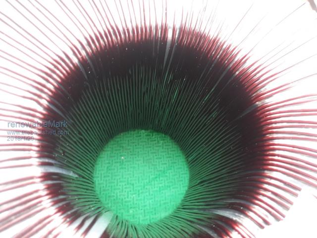
This is the inside of the 3rd winding. Starting to look pretty tight, bit worried if I tried another the turns may need to overlap in the centre and not leave enough room for the primary.Cheers Caveman Mark Off grid eastern Melb