| |
  Page 4 of 8 Page 4 of 8   |
| Author |
Message |
Warpspeed
Guru

Joined: 09/08/2007
Location: AustraliaPosts: 4406 |
| Posted: 09:34am 12 Jun 2018 |
 Copy link to clipboard Copy link to clipboard |
 Print this post |
|
Haha, I recognized that case instantly.
Used to work at Sola, actually still have an identical transformer case out in the shed for a future project.
Very solid and heavy.
Cheers, �Tony. |
| |
Ralph2k6

Senior Member

Joined: 24/09/2017
Location: AustraliaPosts: 129 |
| Posted: 10:47am 12 Jun 2018 |
Copy link to clipboard |
Print this post |
|
I wonder if the DC gauge is indicating the idle current?
That AC load could be within margin of error for the AC meter perhaps?
Very smart looking setup.
Ralph |
| |
Revlac

Guru
Joined: 31/12/2016
Location: AustraliaPosts: 961 |
| Posted: 11:56am 12 Jun 2018 |
Copy link to clipboard |
Print this post |
|
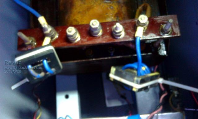
Yeah This transformer Weighs about 27Kg and the idle current in the photo is about 20w +/- a bit for error margin.
I am about to order some more of those meters, see how they go. Think i will check the AC one again just to be sure.
Tony they really are a good strong case, this one was dropped at some stage and tore the transformer mounts out on one side due to the weight. 
Oh rubber mounts in there as well so far the transformer runs silent. 
Will be getting on with the next one soon.
Cheers Aaron
Off The Grid |
| |
johnmc
Senior Member
Joined: 21/01/2011
Location: AustraliaPosts: 282 |
| Posted: 12:04pm 12 Jun 2018 |
Copy link to clipboard |
Print this post |
|
Revlac , your inverter is looking very smart.
cheers john
johnmc |
| |
Revlac
Guru
Joined: 31/12/2016
Location: AustraliaPosts: 961 |
| Posted: 10:07pm 12 Jun 2018 |
Copy link to clipboard |
Print this post |
|
HI John
This thing is mostly made from junk and scavenged parts, I like that sort of a challenge, although it takes longer to build things that way but mostly happy doing it. 
Have not blown up any fets on this build yet, I will do my best to keep it that way.
Cheers Aaron
Off The Grid |
| |
Revlac
Guru
Joined: 31/12/2016
Location: AustraliaPosts: 961 |
| Posted: 10:03pm 14 Jun 2018 |
Copy link to clipboard |
Print this post |
|
I have noticed some fluff build up on the legs of the 8010 IC, the one I'm using, Thought it might be a result of the solder flux I had used but the other IC's are still ok.
Just looking at these conformal coating used on commercial PCB's but horribly expensive in a spray can
Wondering if there is some inexpensive coating that would work ok?
Cheers Aaron
Off The Grid |
| |
Madness

Guru
Joined: 08/10/2011
Location: AustraliaPosts: 2498 |
| Posted: 11:07pm 14 Jun 2018 |
Copy link to clipboard |
Print this post |
|
A spray of Lanox would keep moisture off of it, also is good for on bare copper as flux when soldering.
There are only 10 types of people in the world: those who understand binary, and those who don't. |
| |
tinyt
Guru
Joined: 12/11/2017
Location: United StatesPosts: 431 |
| Posted: 11:13pm 14 Jun 2018 |
Copy link to clipboard |
Print this post |
|
What I do right after using RMA flux solder is dip the entire pcb assembly in isopropyl alchohol (91% at our local pharmacy). I also scrub the flux off with the alcohol using regular toothbrush, then overnight soak.Edited by tinyt 2018-06-16 |
| |
Warpspeed
Guru
Joined: 09/08/2007
Location: AustraliaPosts: 4406 |
| Posted: 12:08am 15 Jun 2018 |
Copy link to clipboard |
Print this post |
|
Definitely isopropyl alcohol, and a good scrub with a toothbrush.
Then flood with more isopropyl alcohol and blow dry with compressed air is how I do it.
Solder flux can be difficult to shift even with just isopropyl.
What works much better is a 50/50% mix of isopropyl and acetone. The mixture works much better than either by itself for some reason.
Jaycar and Altronics have the isopropyl, Bunnings have acetone in the paint section.
I just use the isopropyl by itself for cleaning most things.
But if I am doing a lot of heavy soldering, the magic mixture is worth making up for a really big job.
Edited by Warpspeed 2018-06-16
Cheers, �Tony. |
| |
tinyt
Guru
Joined: 12/11/2017
Location: United StatesPosts: 431 |
| Posted: 02:07am 15 Jun 2018 |
Copy link to clipboard |
Print this post |
|
A word of caution, if the solder flux you are using is the no-clean, organic, etc. follow the manufacturer's recommendation for cleaning.
At work when we were using RMA and alcohol for cleaning, we had no problems. Then we changed to the no-clean, organic and did not change the cleaning method. For no-clean, they looked ugly. For organic, the alcohol caused partial shorts in the pcb assembly. Some the new fluxes require cleaning within 48 hours or don't clean at all.
Thanks Tony for the 50/50% mix, will do that next time.Edited by tinyt 2018-06-16 |
| |
Revlac
Guru
Joined: 31/12/2016
Location: AustraliaPosts: 961 |
| Posted: 11:41am 15 Jun 2018 |
Copy link to clipboard |
Print this post |
|
Thanks for the info.
I used the kester flux pen #951 no clean, read the details on the website and it should be fine, but there was some residue left on one side , probably used too much, time for the tooth brush then.
My farther just showed me a circuit board built about 10years ago it was sprayed with that supercheap/not cheap Export brand clear paint, after dusting off all mouse cr*p it all looks good, tracks and everything in perfect condition, so I expect it would be ok for home made PCB's to preserve the copper tracks at least.
Cheers Aaron
Off The Grid |
| |
Revlac
Guru
Joined: 31/12/2016
Location: AustraliaPosts: 961 |
| Posted: 10:26pm 27 Jun 2018 |
Copy link to clipboard |
Print this post |
|
Just thought I would try a small choke (2 turns)on the L primary (VS1) and see what happens, I think it come from an old computer PSU.
Just seems to make the other choke on VS2 a little more quiet and the idle current is a little better, power consumption is also a bit better on small loads.
Now I have never put the LCD scope on the primary before, and I see this.
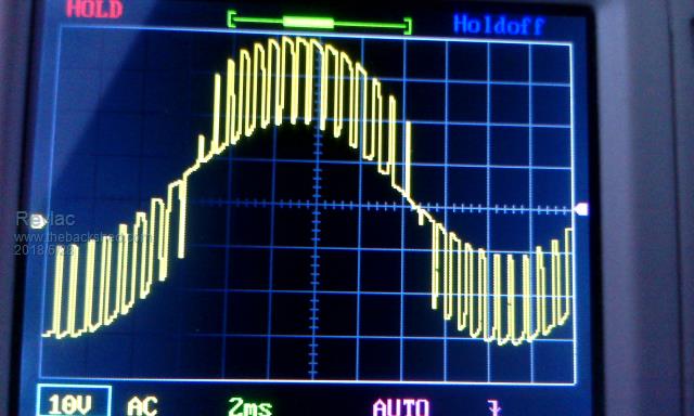
Then tried the secondary output on the transformer and its better but still Rough.
I expect that this is the result of the High Frequency that is not filtered enough by the choke on the primary?? not sure... Perhaps this is the way the LCD oscilloscope reads it?
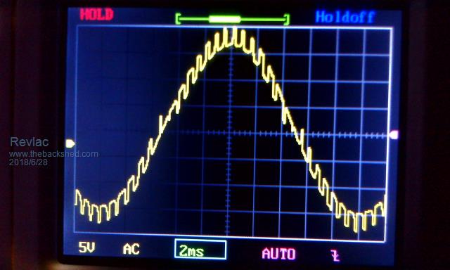
The 230VAC sine wave after the filter and 4UF filter Cap is looking good no blip.
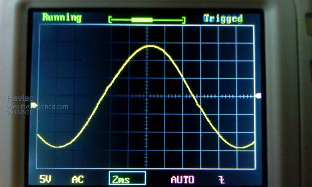
I notice a bit of a blip start to form when a load of about 80w is applied.
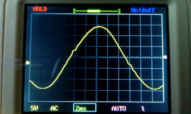
It probably doesn't mean much, what matters is getting it running an keeping it running reliably.
Sticking to the standard build should be good enough, but obviously we don't all have or able to use the exact same parts.
Cheers Aaron
Off The Grid |
| |
Revlac
Guru
Joined: 31/12/2016
Location: AustraliaPosts: 961 |
| Posted: 11:05am 04 Jul 2018 |
Copy link to clipboard |
Print this post |
|
Have been reading about these chokes for a bit, I'm still running with a 4uf cap ATM, So I had an idea to try and see what is going on at the choke.
I put 1 turn of small wire around the core of the EE choke on the primary and took a voltage reading of .28v fine, then give the inverter a 70w load, the voltage on the wire wound around the choke increased to .38v Not really a surprise.
I then tried the same thing with the small choke on the other primary leg, it started at .39v then with the same load applied the the voltage then dropped to .27v per turn????
I thought that was interesting as I didn't expect the voltage to drop on that one.
Tried the little oscilloscope on the wire as well but could not make much sense of it, it looked as if there was another frequency in there but it was irregular and difficult to see.
Also I did hear that pulse in the transformer on startup.
On the new control board (almost finished) I found that after the the 8010 is switched off via pin 6 there is still signals being sent to the lcd port.
Cheers Aaron
Off The Grid |
| |
Madness
Guru
Joined: 08/10/2011
Location: AustraliaPosts: 2498 |
| Posted: 09:46pm 04 Jul 2018 |
Copy link to clipboard |
Print this post |
|
Pin 6 does not turn off the EG8010 as such it controls the SPWM output to start and stop the Inverter output. There is no on-off to completely shut down the EG8010 apart from turning off its power supply. Also there is no way to reset it apart from power off as far as I am aware.
I have found shorting the middle leg of the SCR for overcurrent to ground is a nice way to reset it. If the control board has shut down due to overcurrent doing this reset with pin 6 still turned on results in the LED going off and after 5 seconds the inverter soft starts. However, if it has been in over current for too long as per below you have to do a hard reset (power down) of the EG8010. There is the shorting of the 5W 120 ohm resistor to ground method which has resulted in a few blowups for various people. My preferred method is turn off the DC power and let it drain the capacitors then restart. The shorting of the SCR is good for setting the overcurrent pot as you can test it and if it shuts down just reset it and 5 seconds later it starts running again.
"This function mainly protects power MOSFET and the load. Sixteen seconds after overcurrent protection activates, EG8010 will turn on power MOSFET for 100ms to re-determine load current. If overcurrent issue still exists, EG8010 will repeat the process above every sixteen seconds. If EG8010 runs regularly for more than one minute, it will zero the counter of overcurrent. However, if EG8010 does not function regularly after five 16-second cycle, it will complete turn off the output of SPWM unit. It needs a hard reset to start again."
There are only 10 types of people in the world: those who understand binary, and those who don't. |
| |
Revlac
Guru
Joined: 31/12/2016
Location: AustraliaPosts: 961 |
| Posted: 09:56am 05 Jul 2018 |
Copy link to clipboard |
Print this post |
|
The SCR's arrived yesterday, I can run a wire off the middle leg to a reset switch if need be. so far I have been using the main on/off switch without any problems, However I will have to put some user instructions, I can see the oldman may stuff it up one day. 
I haven't adjusted the over current yet, the pot is just sitting about half way, while still playing around.
It probably should be set fairly high.?
I think once everything is up and running properly the over current situation should be extremely rare, (a short circuit should be rare) but still possible.
When those 2 pips went off the 200A fuses were roasted but did not blow, The battery bank got a fright.
Most often here we can get a locked rotor, either the pump has jammed up or as usual the drill press often gets pushed a bit hard, most that ever happens is the circuit breaker will pop.
Better to pop breakers than fets.
Cheers Aaron
Off The Grid |
| |
Madness
Guru
Joined: 08/10/2011
Location: AustraliaPosts: 2498 |
| Posted: 08:31pm 05 Jul 2018 |
Copy link to clipboard |
Print this post |
|
The overload adjustment is fairly touchy and the tripping point increases quite rapidly. So when adjusting it you really need to have a large motor to startup to test the level or what I use is turning on the AC breaker to the house. With 2 fridges and everything else that is normally connected there is quite a large current required. To set it just gradually increase (counterclockwise) the tripping current until it does not trip, you may trip it quite a few times to get it right so having a fast way to reset will let you do it in a minute or 2 rather than 1/2 an hour.
After setting I would make the reset procedure (1) turn off the switch connected to pin 6 and (2) turn off the main DC breaker, wait 3 minutes and then do your normal cold startup.
Having the right size AC breakers should prevent most overloads but I had a fault in our oven that caused the element to short. It tripped the breaker but when that happened the first time I turned the breaker back on and the Inverter did an overload shutdown. It seems the breaker does not trip easily while being turned on.
I have had a 5KW AC compressor stall on startup and it tripped the 20A AC breaker and the inverter never missed a beat.
Keeping your DC breaker for the inverter as low as possible helps too, mine is now 80A and it has only tripped when there was a major failure (GTI failed due to short to ground). The FETs still blew but they did not explode and there was no damage to any other components or to the PCB. If the breaker is too large the MOSFET legs burn out instead while burning the PCB tracks and fibreglass.
Edited by Madness 2018-07-07
There are only 10 types of people in the world: those who understand binary, and those who don't. |
| |
Revlac
Guru
Joined: 31/12/2016
Location: AustraliaPosts: 961 |
| Posted: 10:43am 26 Jul 2018 |
Copy link to clipboard |
Print this post |
|
After much searching around my junk I managed to find some heat sinks that are of descent size.
They were hiding at the bottom of the aluminum scrap bin, Why they were there?????
They are a little longer than the board but not an issue I see in other builds, Will cut them in half soon and drill/tap for the screws.
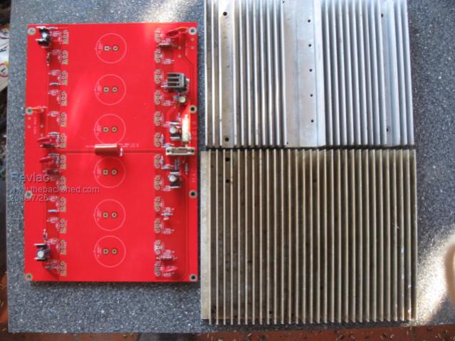
Just wondering about the depth through the PCB that the fets should sit.
Leave the legs long or push them down deep into the PCB?
Preference would be about half way.
Cheers Aaron
Off The Grid |
| |
Madness
Guru
Joined: 08/10/2011
Location: AustraliaPosts: 2498 |
| Posted: 11:35am 26 Jul 2018 |
Copy link to clipboard |
Print this post |
|
Push the FETs all the way home but don't solder them until you have them screwed to the heatsink. If not they won't sit perfectly flat and make good contact with the heatsink. You need to make sure the high side heatsink does not make electrical contact with the top of the PCB. It may even pay to grind a chamfer on the bottom corner near the MOSFET solder joints to prevent shorts there also.
You can over hang the heatsinks but I have found keeping the heatsinks cool is not a problem. Cooling the Toroid needs the fans a lot more.
There are only 10 types of people in the world: those who understand binary, and those who don't. |
| |
Revlac
Guru
Joined: 31/12/2016
Location: AustraliaPosts: 961 |
| Posted: 01:58pm 26 Jul 2018 |
Copy link to clipboard |
Print this post |
|
Thanks Gary
I could put a spacer between the base of the heat sink and the PCB when I start the assembly, that should lift it a little.
Also it looks like I will have to join the 2 positive heat sinks together, perhaps with a copper busbar or just run 2 positive leads, see how it goes anyway.
Cheers Aaron
Off The Grid |
| |
Madness
Guru
Joined: 08/10/2011
Location: AustraliaPosts: 2498 |
| Posted: 08:06pm 26 Jul 2018 |
Copy link to clipboard |
Print this post |
|
You could use a piece of say 3MM Aluminium plate 50mm or so wide to join the 2 halves by screws tapped into the heatsink. I run 2 cables to the positive heat sink, one to the middle of each half even though it is a single piece heatsink.
There are only 10 types of people in the world: those who understand binary, and those who don't. |
| |
| |
Page 4 of 8 |
