Notice. New forum software under development. It's going to miss a few functions and look a bit ugly for a while, but I'm working on it full time now as the old forum was too unstable. Couple days, all good. If you notice any issues, please contact me.
Revlac Guru Joined: 31/12/2016 Location: AustraliaPosts: 961
Posted: 10:19am 09 Aug 2018
Copy link to clipboard
Print this post
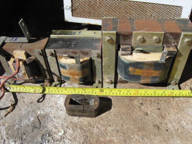
Found some chokes possibly useful. small one at front. cross section 38mm x 30mm and a window of 22mm x 62mm (actually this thing is imperial not metric) Should be ok for the small inverter with appropriate wire/turns.
Rear left medium size. EI 50 x 50mm core cross section, window 25mm x 75mm with a 2mm air gap and running 73 turns of 4mm wire, welded across the laminations.
Center one much the same, not welded and has 30 turns of 70mm flat strap, would be at least .6mm thick, I think and the lugs 13mm x 3mm are soldered to the copper strap, 1mm air gap.
Last one on the right. Getting on to large and heavy, cross section 76mm x 61mm window 114mm x 38mm and 52 turns of 70mm copper strap. 1mm air gap. 2 of these are from a large battery charger.
Measurements are not exact but as close as I could get at the time. I'm not quite ready for them just yet but while there is a chance to learn a few things, why not.? Cheers Aaron Off The Grid
Revlac Guru Joined: 31/12/2016 Location: AustraliaPosts: 961
Posted: 09:21am 13 Aug 2018
Copy link to clipboard
Print this post
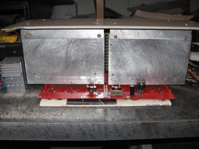
I'm surprised how big this thing is getting, should not have to worry about it heating up too quickly, but the ambient temp around summer will be high, so a good set of fans should keep it happy. Just as a comparison, the heat sink at the far left is from 1 leg (4 fets) of a 4Kw pip inverter, so looks like this is a big improvement at that power level. Cheers Aaron Off The Grid
renewableMark Guru Joined: 09/12/2017 Location: AustraliaPosts: 1678
Posted: 09:43am 13 Aug 2018
Copy link to clipboard
Print this post
Good stuff mate, BTW that heatsink on the tip 35, I have the same size and using the laser heat gun it appears to be getting quite warm, it would be a good idea to upsize that one.Cheers Caveman Mark Off grid eastern Melb
Revlac Guru Joined: 31/12/2016 Location: AustraliaPosts: 961
Posted: 01:51pm 13 Aug 2018
Copy link to clipboard
Print this post
Thanks Mark. I have had some substandard tip35's once before and some got hot when tested, anyway I'm sure I can dig up a larger heat sink, an old computer PSU to sacrifice, should do the trick. May even substitute some other transistor.Cheers Aaron Off The Grid
Revlac Guru Joined: 31/12/2016 Location: AustraliaPosts: 961
Posted: 08:40am 15 Aug 2018
Copy link to clipboard
Print this post
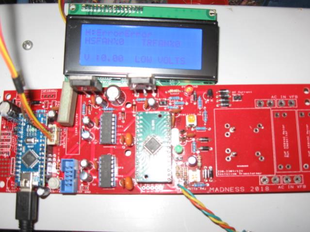
Now have the LCD & Arduino working, Most of the trouble I had was to do with the computers and OS I was using My win7 dual boot with ubuntu, The win7 MBR crashed & fixed it up, but anyway used ubuntu and the usb port was blocked, no permission or something like that, now fixed. Well its a good learning experience doing these things and not all that difficult, I did end up removing the Liquid crystal from the program folder because of a conflict, there may be other ways to do this but it simply works. I don't have the Temp sensors yet.
Cheers Aaron Off The Grid
renewableMark Guru Joined: 09/12/2017 Location: AustraliaPosts: 1678
Posted: 10:01am 15 Aug 2018
Copy link to clipboard
Print this post
Where are you Rev, I have plenty here in eastern Melb if you want to pop by.Cheers Caveman Mark Off grid eastern Melb
Revlac Guru Joined: 31/12/2016 Location: AustraliaPosts: 961
Posted: 10:25am 15 Aug 2018
Copy link to clipboard
Print this post
I'm up here S.E QLD so bit far away, but thanks for the offer mate, I have some on order and not in a hurry. I might have time tomorrow to put some turns on the transformer if all goes well. Still plenty to do. Cheers Aaron Off The Grid
Revlac Guru Joined: 31/12/2016 Location: AustraliaPosts: 961
Posted: 09:50am 17 Sep 2018
Copy link to clipboard
Print this post
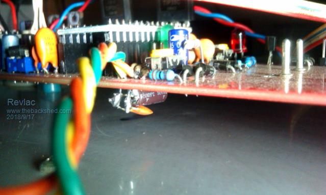
Being busy with other things and haven't made much progress. The temperature sensors are working ok now, for some silly reason must have been half asleep or something, 1 sensor I had connected the negative wire to the center (signal) pin instead of the ground pin, when plugged in it turned into a little heater and burns fingers. The address could still be read in the program but would only read over temp when plugged in, so it was cactus.
The buzzer I had would not buzz, just went pop and crashed the Arduino, So that buzzer turned out to be a dud as well. So I'm not perfect and still make mistakes, mostly little things. All of that is now working nicely. The switch on pin6 has the decoupling caps 104 and a 10uf electro under the circuit board and I will continue to put them on unless at some stage pin 6 gets wired to 5v. The EG8010 data sheet had a cap from pin6 to ground anyway. Cheers Aaron Off The Grid
Revlac Guru Joined: 31/12/2016 Location: AustraliaPosts: 961
Posted: 11:09am 09 Dec 2018
Copy link to clipboard
Print this post
A bit of Choke Testing The double C Core with area 33x53 (with the 2mm air gap), only enough wire to get 17 turns, but enough to try it and see how it works. Now the test run was ok wave form was a little better than the larger EI However the idle current was up to 21.5 watts, Thats the best I could get from it.
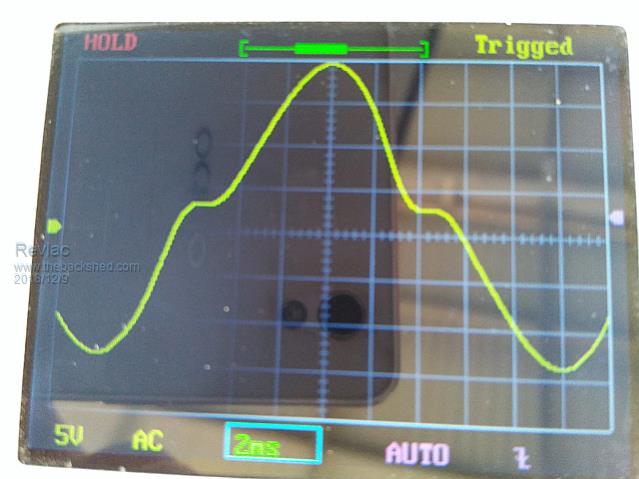
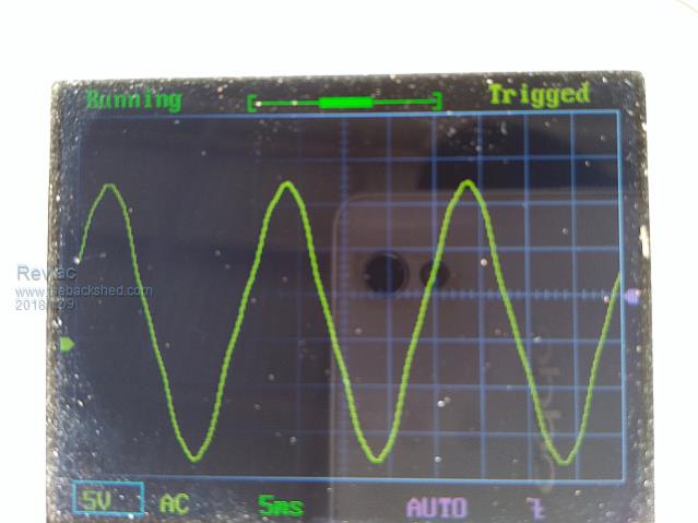
That EI 50mm x 50mm core with the 30 turns had a 1mm gap and had a horrible waveform as is, the idle current was good 23w but the wave was a bit wobbly then give it 50w load and the wave had a large flat at zero crossing (also have a little ferrite EE in series) The other EI 50mm x 50mm choke with 73 turns was much worse than this, so no photo.
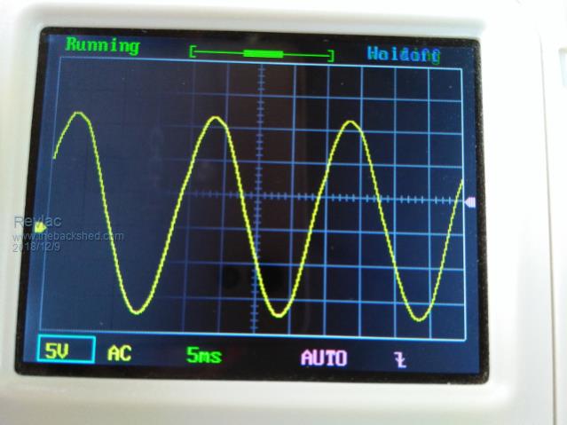
Added a 3mm air gap and that was a vast improvement but still not as good as it should be. After messing with the clamp and bolts it could be adjusted up to 6mm air gap, so slammed it together all tight and tried it, the idle current was down just 18watts and a bit better waveform. So keep going, added up to 10mm air gap, idle still 18watts wave form at idle is perfect, just some small peeks at the top of the wave under load. Now on 14mm air gap and still 18watts idle, perfect wave and then loaded, sine wave still perfect. 18watts is as low as it will go, Now from doing this it looks like adjusting the air gap on this EI Choke has no effect on the idle current after the 2mm air gap, but a significant difference to the waveform at idle and under load, 14mm is large, in fact it is almost off. I'm getting the idea that too many turns is not so good unless the air gap can be made BIG.
I think this is heading in the right direction.
Cheers Aaron Off The Grid
Tinker Guru Joined: 07/11/2007 Location: AustraliaPosts: 1904
Posted: 04:06pm 09 Dec 2018
Copy link to clipboard
Print this post
I see you are having fun Aaron . That last sine wave looks like the one on my inverter. You want that with no or full load. Note that different kinds of load do change the sine wave a bit.
That 14mm air gap sounds ridiculous, you must be doing something strange. How do you measure idle power? Current from battery with clamp meter times battery voltage, no load? Around 20w looks OK for a 6KW inverter, I think mine was 21W, have to find that note I scribbled to confirm.
Remember, you can't reduce the core's magnetising current, no matter what you do to the chokes. You might have measured it when you re wound that toroid. A few extra turns on the secondary gets it a little lower but there is a limit. The other fixed loads are your electronics, as long as nothing gets unduly hot there you are stuck with that (small) extra load.
If you are into tinkering with chokes a good idea is to build that inductance saturation test rig warpspeed posted some time ago. You need to wind a test coil though, 100-150 turns work well. Note, this is just to test for saturation so you can use 1.5mm wire or so for the test coil.
The number of turns on you working choke is a compromise between inductance (you want as much as practical) and of wire cross section for the high currents. My big choke has 18 turns, 45mm sq wire (18 x 1.8mm wire in parallel) and uses a 2mm air gap. 2 x large Aerosharp C cores were used to make a pseudo E core. Works for me.Klaus
renewableMark Guru Joined: 09/12/2017 Location: AustraliaPosts: 1678
Posted: 08:32pm 09 Dec 2018
Copy link to clipboard
Print this post
Good progress mate, Warp was an enormous help when I needed to sort my choke out (P65 on my build)
What caps have you got connected to the secondary?Cheers Caveman Mark Off grid eastern Melb
Tinker Guru Joined: 07/11/2007 Location: AustraliaPosts: 1904
Posted: 02:08am 10 Dec 2018
Copy link to clipboard
Print this post
When looking at my notes I saw that a correction of the above was due. It should read:
Around 20W looks OK for a 3KW inverter, I think mine (6KW) was 29W idle, including the info panel load.
My small 1.5KW test inverter idles at 14.5W for comparism. Klaus
Revlac Guru Joined: 31/12/2016 Location: AustraliaPosts: 961
Posted: 11:10am 10 Dec 2018
Copy link to clipboard
Print this post
@ Tinker Yep I am having fun with this choke testing bit, what I was trying to do was get a visual image of what was going on with this particular core as it was made/wound for 50amp battery charger. As I don't have any test gear this seemed to be an easy way to determine which direction to go. And yes such a huge air gap is kinda ridiculous and at that the saturation limit would beyond anything I could put through it. What this is telling me is that I could have archived the desired results by taking off a few turns on this particular choke, as it looks like there is too much inductance, and by adding that air gap reduces it a bit. (if I have understood the notes correctly)
I will still build that other choke using the 2 pair of C cores with 18 turns, will make use of it.
The Idle current was measured with a current shunt and meter connects between the battery and inverter so it is the total consummation. I just ordered a nice little clamp meter, should be here in a week or so. and then test a few things around the place, might get interesting. Cheers Aaron Off The Grid
Revlac Guru Joined: 31/12/2016 Location: AustraliaPosts: 961
Posted: 11:13am 10 Dec 2018
Copy link to clipboard
Print this post
@ Mark I'm running 5uf for these tests. I built a little signal generator to do a resonance test, but have not tried it yet. I still Have a bit of work to do on the Mad inverter, progress has been slow due to other things. Yesterday, Started building a frame to mount some more solar panels over the top of the water tanks, hope to get back to the inverter soon.Cheers Aaron Off The Grid
brucedownunder2 Guru Joined: 14/09/2005 Location: AustraliaPosts: 1548
Posted: 08:47pm 11 Dec 2018
Copy link to clipboard
Print this post
Just checkin in ,
Been watching you guys ,busy little bee,s , that�s for sure.
Have made contact with Aaron,and hope to visit soon.
Dry as an Arabs thong around here,hoping. For some rain tomorrow,my tanks are full,thanks to recent short storms.
On the solar front ,still haven,t wired my 2.5kw of panels I put up on the grape vine trellis ,but we,ve had a few storms and they appear solid enough ,so that�s a good start.
Mark, sounds like your new baby is coming along nicely ,,,,,urrr,the inverter baby that is ,best get that straight ,hey?. Ok, you all keep busy ,stay careful,
BruceBushboy
Revlac Guru Joined: 31/12/2016 Location: AustraliaPosts: 961
Posted: 06:48am 09 May 2019
Copy link to clipboard
Print this post
Managed to Give the Mad Inverter its first test run today, coupled to the C core transformer, its sitting on the coffee table outside in a rats-nest arrangement running off a small set of batteries so could not run for long. Working ok, still a few checks to do, the next job will be to build it into the case nice and neat, hopefully. I will post some details later when there is some more progress. Cheers Aaron Off The Grid
BenandAmber Guru Joined: 16/02/2019 Location: United StatesPosts: 961
Posted: 02:02am 10 May 2019
Copy link to clipboard
Print this post
I don't know how I miss this post it is awesome and I'll have to read it from the beginning to the end when I get some more time thank you for posting itbe warned i am good parrot but Dumber than a box of rocks
Revlac Guru Joined: 31/12/2016 Location: AustraliaPosts: 961
Posted: 10:16am 11 May 2019
Copy link to clipboard
Print this post
Hi Ben and Amber Your inbox is full, needs a bit of a clean out so I can Reply. Cheers Aaron Off The Grid
Revlac Guru Joined: 31/12/2016 Location: AustraliaPosts: 961
Posted: 10:06am 21 Jun 2019
Copy link to clipboard
Print this post
Thought it was about time for an update.
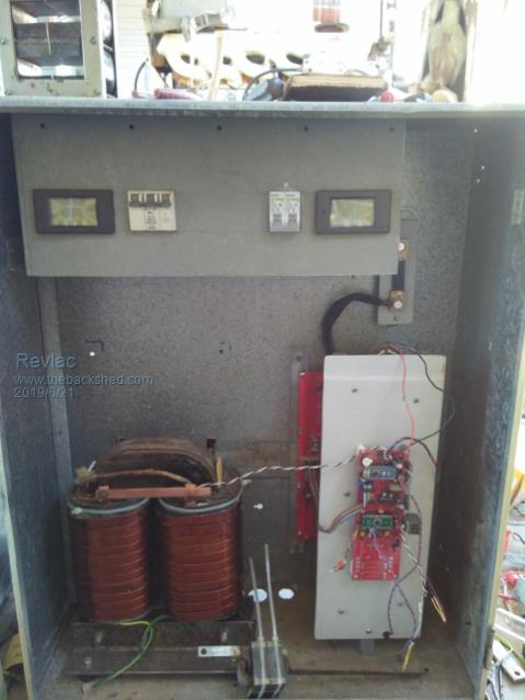
The cabinet is actually the old meter box that used to supply the house, thought this would be a good use for it and rather fitting purpose, as its previous contents was no longer required or wanted (Lightning attracting).
Plenty of room for airflow around everything, still need to do some wire routing and wind up another iron core choke and that should mount up nicely just above the main transformer, will also have a ferrite choke in series with it if necessary.
Mounted up the meters today and the panel will hinge down for access to the capacitors, filters and other things, I thought it might look a little more neat and tidy by hiding all the Ac connections and wiring up there.
Trying to keep all the AC and DC wiring apart to try and avoid noise and interference..Hopefully.
Anyway so far so good.Cheers Aaron Off The Grid
Madness Guru Joined: 08/10/2011 Location: AustraliaPosts: 2498
Posted: 11:41am 21 Jun 2019
Copy link to clipboard
Print this post
Looking good Aaron, you could have left one of the old meters in there and had it spin backwards for a laugh.There are only 10 types of people in the world: those who understand binary, and those who don't.