
|
|
Forum Index : Electronics : Experimental sinewave inverter designs
| Author | Message | ||||
| noneyabussiness Guru Joined: 31/07/2017 Location: AustraliaPosts: 506 |
What i mean is, if you say feed a 5% pwm signal into the trigger pin, will the low side then be on 95% or 5% . Just trying to get my head around it I think it works !! |
||||
| Warpspeed Guru Joined: 09/08/2007 Location: AustraliaPosts: 4406 |
The outputs are not complimentary. Both the upper and lower mosfets turn on and off together with that particular driver chip. If you drive the single input with 5% PWM, both outputs will be 5% PWM, and switch together simultaneously. Its intended for driving diagonal half bridge flyback supplies, where both mosfets turn on and off simultaneously. Its a wierdo chip made for an unusual application. http://www.industrial-electronics.com/switching-power-supply_2-5.html If you want to use it to drive a full bridge PWM inverter, you need to cross over the drive so that diagonal mosfets turn on and off together. That is clearly shown in the manufacturers application notes. Its also why dead time and non dead time version of the chip are made. Cheers, �Tony. |
||||
| poida Guru Joined: 02/02/2017 Location: AustraliaPosts: 1389 |
Warpspeed, are you sure about this? The IR21844 is a 1/2 bridge driver as described by IR. here is the design guide: 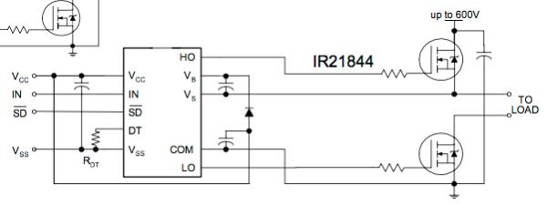 The two wires labelled "to load" are connected together and make up one of the two terminals to which we connect the primary winding. here is the logic diagram: 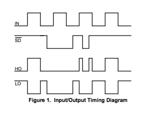 You can see the effect of Shutdown, when low, no outputs, when high, outputs are enabled depending on the state of IN pin. When shutdown is not in effect, that is, pulled high, LO and HO reflect the state of IN. HO = IN LO = compliment of IN (or NOT IN if you like) The IR 21844 is different to the IR2110S as used in the EG002 where both HO and LO have independent inputs (HIN and LIN). We need to provide dead time with these two signals, HIN and LIN and drive one in opposite (logical NOT, or compliment) to the other. here is the logic diagram for that part: 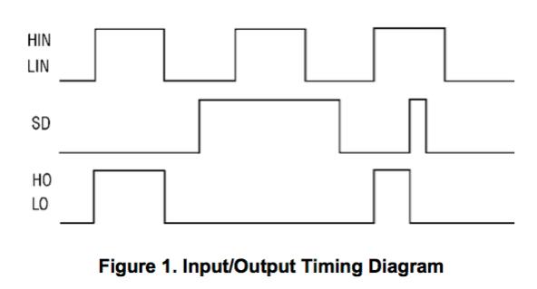 and the design guide: Notice it has the two "to load" terminals as well. 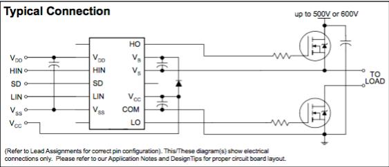 So, Tinyt, connect PWMA = pin 9, PWMB to pin 7 and do this: 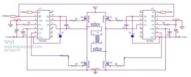 and it will be the same as my prototype. I use only one choke, not two. wronger than a phone book full of wrong phone numbers |
||||
| Warpspeed Guru Joined: 09/08/2007 Location: AustraliaPosts: 4406 |
I have just been looking at a whole bunch of IR21844 circuits on the internet, and you are quite correct. Its a conventional half bridge driver for two series connected mosfets. Cheers, �Tony. |
||||
| tinyt Guru Joined: 12/11/2017 Location: United StatesPosts: 431 |
I hope I got it this time: 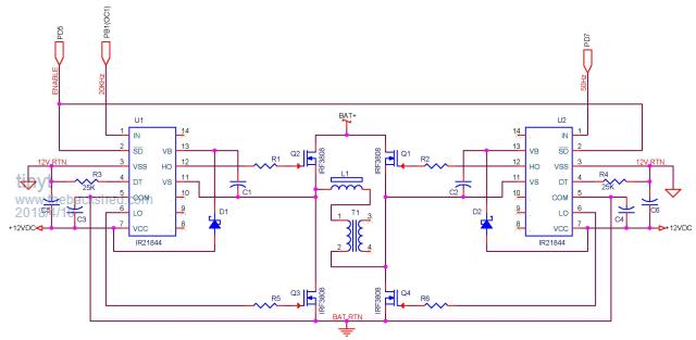 |
||||
| poida Guru Joined: 02/02/2017 Location: AustraliaPosts: 1389 |
I like it. It is similar to what I have running on the bench. When starting it up, only install one mosfet each leg, use a bench power supply with current limit. When running my prototype with 27V DC supply into a 3000VA toriod I only need 0.5A under zero load. The finer points of the power bridge design I will leave to others, except to say that you probably need something like 4R gate drive resistor, 10K R from gate to ground and a small diode permitting fast switch off, parallel to the 4R resistor for all 4 switch legs. wronger than a phone book full of wrong phone numbers |
||||
oztules Guru Joined: 26/07/2007 Location: AustraliaPosts: 1686 |
My arduino is very very basic..... Now I find that I will have to spend the next 12 months deciphering the code poida has shown us... looks terribly daunting for me to say the least. There are more new terms in there than I know at the moment.. so my syntax needs to increase by a 100% or more. I may never get there, but it looks worth the effort... at least I have plenty of eg8010 chips to fall back on.... but getting control of the process is important to me. On my arduino editor/complier it fails to compile because of a "incompatible types in assignment of �int� to �uint16_t", which appears to be because of a definition of "l" not being available, so am going to just define l as an unsigned int, and see what happens on the bench in the next few days... hopefully when I get time. At least it compiles now... what it does to the outcome is yet to be determined  Thanks to poida for his ( to me) way over top.... mad programming skills... I may never get it, but will definitely try to. .....dazed and confused yet again.... oztules Village idiot...or... just another hack out of his depth |
||||
| poida Guru Joined: 02/02/2017 Location: AustraliaPosts: 1389 |
Oz: I tried to compile the code and I got the same error. sorry! where it has for(t=0.0,i=0; i <= NPWM; i++,t += 3.14159/ (float) NPWM) { u = 16384.0 * sin(t); l = (int)u; } change it to for(t=0.0,i=0; i <= NPWM; i++,t += 3.14159/ (float) NPWM) { u = 16384.0 * sin(t); l = (int)u; // <- this line } It now compiles and runs correctly. I can happily answer questions on coding until the cows come home. I have been at it for 30 years. I use the Arduino programming environment for it's fast edit/compiler/test cycle. I do not use all the Arduino system functions though. I actually started out on Atmega programming in pure assembly (for my job) way, way before Arduinos become a thing. wronger than a phone book full of wrong phone numbers |
||||
| oztules Guru Joined: 26/07/2007 Location: AustraliaPosts: 1686 |
Sorry poida, I looked and looked... but the only difference I can see is the comment.//<-this line, other than that the lines appear to be the same.... so I then cut and pasted.in the vain chance I didn't see something obvious... but same result, and same error as I sort of expected. So I think you thought you changed it.... but didn't. If I define the l as a unsigned int, the thing compiles... but I wonder what the first bit in the 16 will do to the code output. Im guessing it is not used, and the array will form as anticipated... so what is the real change?  .. hang on, it is the int function that uses the first bit for bookkeeping, so maybe it won't effect it..... hmmmm... .. hang on, it is the int function that uses the first bit for bookkeeping, so maybe it won't effect it..... hmmmm...........oztules Village idiot...or... just another hack out of his depth |
||||
| poida Guru Joined: 02/02/2017 Location: AustraliaPosts: 1389 |
Ahh, something in the forum posting code is removing square brackets. I included them in the text I wrote but those square brackets were removed. so, to avoid any further issue I place a screen capture of the code. So, backshed forum software, remove these square brackets!!! 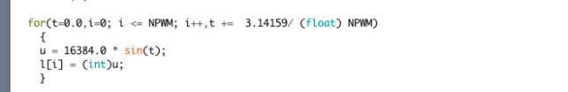 wronger than a phone book full of wrong phone numbers |
||||
| oztules Guru Joined: 26/07/2007 Location: AustraliaPosts: 1686 |
yep... that sorted it out, thanks.... now to get a board and see it load and read out some serial stuff ........oztules Village idiot...or... just another hack out of his depth |
||||
| poida Guru Joined: 02/02/2017 Location: AustraliaPosts: 1389 |
Oz, I use the Arduino program's "serial plotter" function frequently. It's very good to see variable's changes over time. put in setup() Serial.begin(115200); and put in loop() Serial.print(ch0*10.0); Serial.print(" "); Serial.print(ch2*10.0); Serial.print(" "); Serial.print (vpwr/100.0); Serial.println("0 12"); this will give a real time graph of the three variables AC set point, AC output and PWM modulation Because sending data out the serial port takes some uninterruptable time the inverter runs a little unhappily. When no serial data is sent out, the inverter runs smooth as silk. the graph looks like this for my system: 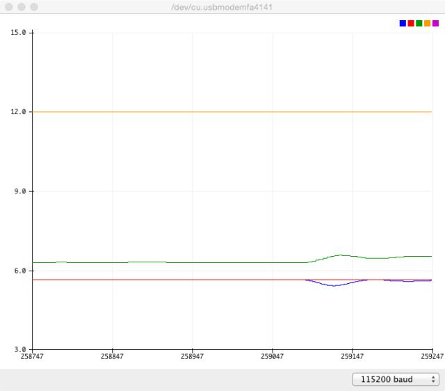 Blue is AC output voltage Red is AC voltage setpoint (from potentiometer) Green is PWM modulation The 0 and 12 set fixed minimum and maximum values for the plot, otherwise it continually rescales and changes offsets. The bump is due to me switching on a load, causing more PWM modulation and an error in the PID closed loop that was soon corrected. wronger than a phone book full of wrong phone numbers |
||||
| tinyt Guru Joined: 12/11/2017 Location: United StatesPosts: 431 |
Hi Poida, Will this require major modification to compile in Atmel Studio 7? |
||||
| oztules Guru Joined: 26/07/2007 Location: AustraliaPosts: 1686 |
Thanks poida. I have nothing to test it in at the moment...... but I got hold of the virtronics simulator... which would not create the wave array  , so had to modify the for loop to read.. , so had to modify the for loop to read.."void setup() { t=0.0; for(i=0; i <= NPWM; i++) { t = t+3.14159/ (float) NPWM u = 16384.0 * sin(t); l = (int) u; // <- this line } " It then ran ok to do the loop, and allowed me to see the array form in the variables column... first value is 257 ..... then up to 16383 and then back down to zero at NPWM=199. If I did the mod correctly, zero crossing occurs when npwm=199, and goes neg257 for NPWM=200..... so I have offset it by one somehow... or the NPWM goes from 0 to 200 so 201 array places, which would explain it.... was I supposed to see -257.... I thought you set the array as unsigned, so I expected to see 257 not -257... and I would have thought neither should appear here. Should I rejig the "for loop" to get u=0 at i=199, and kill off NPWM=200 to 199? For the first array point, we have for(i=0,t=0.0; i <= NPWM; i++,t += 3.14159/ (float) NPWM) So when i and t are initialized at 0, then t=.0150795, and so then u=257 ( or int(257.3484....)) Is this correct, or did I screw the for loop up?.. or is the simulator a bit off? Haven't gone further at this stage as this is as far as I can claim much understanding at this point in time. Edit: I see the forum killed off the square braces in that post as well.... I put it in too  Edit 2: I decided to try to add the braces, but I see in the edit screen... they are there, so I guess the forum interpreted the braces around the i to be a smiley of some kind it couldn't display... that explains it I think... Glen.... what can we do, surely the micro forum must have run into this problem too? Edit 3:yep just read the micromite page, and Glen mentions it here: For this forum we can use (MM) for MaxiMite, (DM) for DuinoMite, and this could even be extended to (PX) for Picaxes, and (MC) for all other micro controllers. For example, (PX)Picaxe LCD driver means this is a discussion about the PicAxe microcontroller. You'll notice I've used round brackets instead of square brackets, because this forum software tries to interpret anything inside a square bracket as formatting and we may get some unexpected effects if we use square brackets. " So we are not the first to notice this behavior... .....oztules Village idiot...or... just another hack out of his depth |
||||
| poida Guru Joined: 02/02/2017 Location: AustraliaPosts: 1389 |
Tinyt, It will need some modification to compile under Atmel Studio if you can not make calls to Arduino library functions. pinMode() noInterrupts() analogRead() digitalRead() need translation into straight assembler/C code I can't do it off the top of my head right now. I am at work. Why you not using Arduino IDE? It allows you to use the Atmel AVR ISP II interface if needed (i.e. the destination chip has no boot loader) I have the Codevision AVR compiler. I used this when working in assembler/C. I will need to download and install Atmel Studio to set up a duplicate environment to permit me to play along with you as we sort out the issues. wronger than a phone book full of wrong phone numbers |
||||
| poida Guru Joined: 02/02/2017 Location: AustraliaPosts: 1389 |
Oz: I attempted to download the virtronics simulator but the Windows7 defender identified it as a virus and so after downloading, it deleted it. I won't bother trying to replicate your environment. The initialization of the Loop with Square-brackets-we-must-never-post is going to result in a table of 16 bit signed integers, NPWM elements in the array, currently set to 200 here are the values I got. Out by one or so is not important. index 0 = 0 index 1 = 257 index 2 = 514 index 3 = 771 index 4 = 1028 index 5 = 1285 index 6 = 1541 index 7 = 1797 index 8 = 2053 index 9 = 2308 index 10 = 2563 index 11 = 2816 index 12 = 3070 index 13 = 3322 index 14 = 3574 index 15 = 3824 index 16 = 4074 index 17 = 4323 index 18 = 4570 index 19 = 4817 index 20 = 5062 index 21 = 5307 index 22 = 5549 index 23 = 5791 index 24 = 6031 index 25 = 6269 index 26 = 6506 index 27 = 6742 index 28 = 6975 index 29 = 7207 index 30 = 7438 index 31 = 7666 index 32 = 7893 index 33 = 8117 index 34 = 8340 index 35 = 8560 index 36 = 8778 index 37 = 8995 index 38 = 9209 index 39 = 9420 index 40 = 9630 index 41 = 9837 index 42 = 10041 index 43 = 10243 index 44 = 10443 index 45 = 10640 index 46 = 10834 index 47 = 11026 index 48 = 11215 index 49 = 11401 index 50 = 11585 index 51 = 11765 index 52 = 11943 index 53 = 12118 index 54 = 12289 index 55 = 12458 index 56 = 12624 index 57 = 12786 index 58 = 12945 index 59 = 13102 index 60 = 13254 index 61 = 13404 index 62 = 13550 index 63 = 13693 index 64 = 13833 index 65 = 13969 index 66 = 14102 index 67 = 14231 index 68 = 14357 index 69 = 14479 index 70 = 14598 index 71 = 14713 index 72 = 14824 index 73 = 14932 index 74 = 15036 index 75 = 15136 index 76 = 15233 index 77 = 15326 index 78 = 15415 index 79 = 15500 index 80 = 15582 index 81 = 15659 index 82 = 15733 index 83 = 15803 index 84 = 15869 index 85 = 15931 index 86 = 15989 index 87 = 16043 index 88 = 16093 index 89 = 16140 index 90 = 16182 index 91 = 16220 index 92 = 16254 index 93 = 16285 index 94 = 16311 index 95 = 16333 index 96 = 16351 index 97 = 16365 index 98 = 16375 index 99 = 16381 index 100 = 16384 index 101 = 16381 index 102 = 16375 index 103 = 16365 index 104 = 16351 index 105 = 16333 index 106 = 16311 index 107 = 16285 index 108 = 16254 index 109 = 16220 index 110 = 16182 index 111 = 16140 index 112 = 16093 index 113 = 16043 index 114 = 15989 index 115 = 15931 index 116 = 15869 index 117 = 15803 index 118 = 15733 index 119 = 15659 index 120 = 15582 index 121 = 15500 index 122 = 15415 index 123 = 15326 index 124 = 15233 index 125 = 15136 index 126 = 15036 index 127 = 14932 index 128 = 14824 index 129 = 14713 index 130 = 14598 index 131 = 14479 index 132 = 14357 index 133 = 14231 index 134 = 14102 index 135 = 13969 index 136 = 13833 index 137 = 13693 index 138 = 13550 index 139 = 13404 index 140 = 13254 index 141 = 13102 index 142 = 12945 index 143 = 12786 index 144 = 12624 index 145 = 12458 index 146 = 12289 index 147 = 12118 index 148 = 11943 index 149 = 11765 index 150 = 11585 index 151 = 11401 index 152 = 11215 index 153 = 11026 index 154 = 10834 index 155 = 10640 index 156 = 10443 index 157 = 10243 index 158 = 10041 index 159 = 9837 index 160 = 9630 index 161 = 9420 index 162 = 9209 index 163 = 8995 index 164 = 8778 index 165 = 8560 index 166 = 8340 index 167 = 8117 index 168 = 7893 index 169 = 7666 index 170 = 7438 index 171 = 7207 index 172 = 6975 index 173 = 6742 index 174 = 6506 index 175 = 6269 index 176 = 6031 index 177 = 5791 index 178 = 5549 index 179 = 5307 index 180 = 5062 index 181 = 4817 index 182 = 4570 index 183 = 4323 index 184 = 4074 index 185 = 3824 index 186 = 3574 index 187 = 3322 index 188 = 3070 index 189 = 2816 index 190 = 2563 index 191 = 2308 index 192 = 2053 index 193 = 1797 index 194 = 1541 index 195 = 1285 index 196 = 1028 index 197 = 771 index 198 = 514 index 199 = 257 I think you are getting the idea how I use this table. I set up 2 timers. TIMER2 is to call the TIMER2_OVF_vect Interrupt service routine 100 times a second. Each time this code is run, it toggles f50 variable which can be either 1 or zero, so it starts 0, goes to 1, back to 0, back to 1... Each change happens at 100Hz. F50 is used to decide if we use the sine table AS IS or altered. TIMER1 is used to output the 20KkHz PWM with the desired duty cycle. After setup() runs, TIMER1 is running with a zero duty cycle. It keeps running forever. We can stick into a register a value that defines the duty cycle. In this case the register is OCR1. OCR1 can be anything from 0 to PPWM (which is currently 800) if we put 1 into OCR1, the duty cycle now becomes 1/800 put 400 into it and it's 400/800 or 0.5 or 50% Depending on the value of f50, we put the current contents of the sine array into OCR1 or we put (800 - sine array) into OCR1. This way we get a sine wave or (1 - sinewave), needed to produce a sine wave when we subtract the 50Hz square wave from it. Each time TIMER1_OVF_vect code is run (at 20kHz) the counter we use to index the sine array is incremented. No need to check for overflow, it never will - the counter is reset to zero each time TIMER2 code is run. wronger than a phone book full of wrong phone numbers |
||||
| tinyt Guru Joined: 12/11/2017 Location: United StatesPosts: 431 |
I have the obsolete AVR Studio and was able to use the Atmel AVRISP MKII (and clone) programmer for a long time. After I installed the Arduino IDE, the AVRISP MKII programmer is no longer recognized by AVR Studio. When I un-installed the Arduino IDE and installed Atmel Studio 7, it recognized the genuine AVRISP MKII but not the clone. But it never fixed the old AVR Studio. Maybe too much junk in my computer and/or incorrect install. Also, if I remember, there is no debug function in the Arduino IDE. That is why maybe I can do some tracing in Atmel Studio 7. Thanks. |
||||
| Warpspeed Guru Joined: 09/08/2007 Location: AustraliaPosts: 4406 |
Being rather mathematically and software challenged myself, I have a question for the math junkies that hang out here... Its pretty straightforward to find the sine of an angle, there are published tables and many on line calculators that do that directly to great precision. But I want to do it in the opposite direction. How do I find the sine angle that corresponds to a known magnitude ? 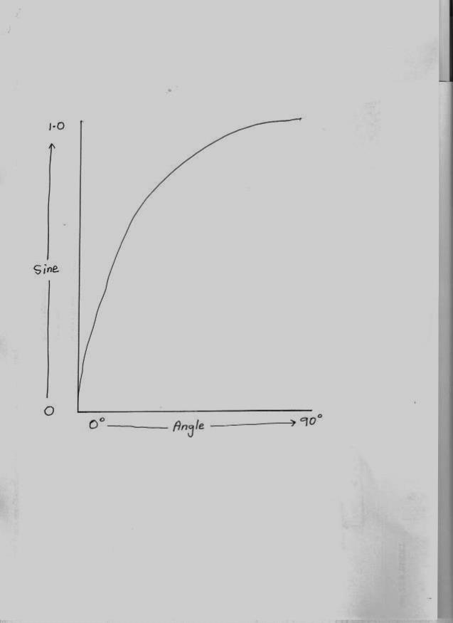 Cheers, �Tony. |
||||
| oztules Guru Joined: 26/07/2007 Location: AustraliaPosts: 1686 |
Thanks poida. my numbers are identical, but my for loop produces an extra iteration because of 0 to 200 inclusive. I will fix that and my -257 will go away too... and I can see why that all happened now. The simulator works in my linux via wine, so virus is of no concern to me. I will get a physical device up soon... but simulator gives all stack calls, outputs, etc etc... so will be invaluable to me to learn whats under the hood. With your explanations, I should get the drift before the next ice age perhaps. your a wizard. .......oztules Village idiot...or... just another hack out of his depth |
||||
| poida Guru Joined: 02/02/2017 Location: AustraliaPosts: 1389 |
Warpspeed: you want you use the C function asin() it returns the angle in radians of the arcsine of the supplied argument Some environments don't have full math support. Then there are formulae that give arcsine from combinations of arctan and simple math. If your situation has the asin() function but you need it to run fast, I would use a lookup table plus a little code to determine which quadrant you are in. Start with a table 0 to 1.0 corresponding to 0 to 90 deg j=0 for (th = 0.0; th < 1.0; th += 0.01) { j = j + 1 lookuptable(j) = asin(th) } code could look like: v = sine of angle float fast_asin(v) { if (v < -1.0 || v > 1.0) return ERROR if (v < 0) return (- lookuptable(v * 100)) else return (lookuptable(v * 100)) } this code would need 2 floating point compares, one FP multiply one FP to int conversion and an array lookup. Of course there is a problem for arcsin(), there are two different angles that give the same sin() for any span of 360 degrees. wronger than a phone book full of wrong phone numbers |
||||
