
|
|
Forum Index : Electronics : Experimental sinewave inverter designs
| Author | Message | ||||
| Warpspeed Guru Joined: 09/08/2007 Location: AustraliaPosts: 4406 |
[quote]Start with a table 0 to 1.0 corresponding to 0 to 90 deg[/quote] Yes, that is what I already have, a 1K lookup table, all now done, a program written in HC11 assembler and it works fine producing a nice looking sine. Table input 000 to 3FF amplitude, output 00 to ff for the angle. That covers one ninety degree quadrant nicely. The other three quadrants are derived from that as you suggest. Its all now done, written in assemble and it works fine producing a nice looking sine wave with a measured one percent distortion. My existing 1K lookup table was crudely derived by reading a sine lookup table backwards, and there is definitely some rounding in there, which gets pretty serious up near full amplitude, where the amplitude hardly changes right at the peak. I was wondering if there was a simple easy way to get more accurate figures near the peak. Then perhaps edit my existing lookup table if necessary for better accuracy. I don't have anything here with arcsin, but will do some internet searching. Thank you very much for the help. Cheers, �Tony. |
||||
| poida Guru Joined: 02/02/2017 Location: AustraliaPosts: 1392 |
Warpspeed: v asin(v) 1000 3E8 0.98 1.35 DC 1001 3E9 0.98 1.36 DD 1002 3EA 0.98 1.36 DE 1003 3EB 0.98 1.37 DE 1004 3EC 0.98 1.37 DF 1005 3ED 0.98 1.38 E0 1006 3EE 0.98 1.38 E1 1007 3EF 0.98 1.39 E2 1008 3F0 0.98 1.39 E3 1009 3F1 0.99 1.40 E4 1010 3F2 0.99 1.41 E5 1011 3F3 0.99 1.41 E6 1012 3F4 0.99 1.42 E7 1013 3F5 0.99 1.42 E8 1014 3F6 0.99 1.43 E9 1015 3F7 0.99 1.44 EA 1016 3F8 0.99 1.45 EB 1017 3F9 0.99 1.45 EC 1018 3FA 0.99 1.46 EE 1019 3FB 1.00 1.47 EF 1020 3FC 1.00 1.48 F1 1021 3FD 1.00 1.49 F3 1022 3FE 1.00 1.51 F5 1023 3FF 1.00 1.53 F8 1024 400 1.00 1.57 100 When using 8 bits to represent the angle, resolution loss appears to me to be a problem once the sin() value gets to 1020 or so. Then the rate of change of the angle becomes more than one for each unit increase in v To get degree or sub degree accuracy of the angle at these large values, you will need more resolution in the input value, not just 0 - 1023 The function asin() has a rate of change that is too fast for single degree resolution using 10 bits of input at these angles. wronger than a phone book full of wrong phone numbers |
||||
| Warpspeed Guru Joined: 09/08/2007 Location: AustraliaPosts: 4406 |
I did it with pencil and paper, but the results are the same. About one bit time steps between 1005 and 1020 which is fine. 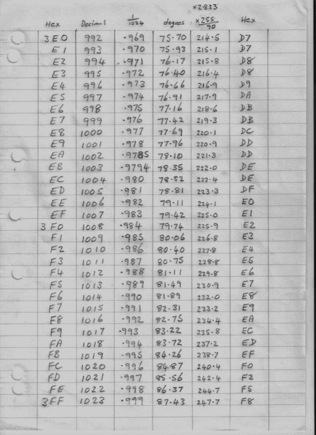 Time resolution of 256 bits (per quadrant) is 1K bits for one full cycle. With 256K x 8 ROM that gives me 256 different lookup tables. This is the actual inverter output waveform it produces on an oscilloscope, at 100v per division. There are 81 steps peak to peak. 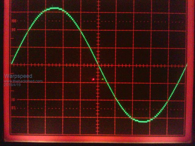 This is not a simulation or any kind of trick. Its the actual mains waveform driving things in my home right now. The inverter I am using right now has only one lookup table and cannot regulate the output voltage. The dc input must be regulated. The next inverter will have a large number of different lookup tables (256) that will switch very fast right at the zero crossings where the output is always at zero volts. So every new cycle will be corrected in voltage every 20mS. Should respond super fast to load changes. Cheers, �Tony. |
||||
| poida Guru Joined: 02/02/2017 Location: AustraliaPosts: 1392 |
Warpspeed: this waveform is looking good from a THD viewpoint. The steps resulting from the discrete digital nature adds up to 1 or 2% probably less. This is near enough for jazz. I was wondering why you need an accurate asin() function: what is the application, if I may ask? I do scaling of a single sine table on the fly. It is easily fast enough. The step change from one power level to another is usually smooth via stages. Having a range of lookup tables and switching between them will be faster than my way: a fast change of memory address verses a 32 bit multiply and 14 bit shift. I see no deficiency in either your design or mine. Results from experimentation has shown to me that regulation of an inverter is primarily a function of the transformer, primary winding diameter etc. and the current fed into it. This is automatic and due to the transformer and the DC supply. The PWM is less important and I would rate it maybe 20% of the regulation function. It's still vitally important in that it regulates the voltage output level. wronger than a phone book full of wrong phone numbers |
||||
| Solar Mike Guru Joined: 08/02/2015 Location: New ZealandPosts: 1129 |
Would there be any advantage to extending the data bus width to 10bits, by using 2 EEPROMS and 8 bits from one 2 from the other, the crystal osc frequency would have to be higher and 3 x 4bit cascaded magnitude comparators required. This would give better resolution. Cheers Mike |
||||
| Warpspeed Guru Joined: 09/08/2007 Location: AustraliaPosts: 4406 |
The way it is the moment, with 81 steps (40 up, zero, and 40 down)the measured total harmonic distortion on an HP333A distortion analyser is exactly 1.0% without any output filtering. With only 41 steps and exactly half the output amplitude, the THD rises to a measured 1.7%. A 2:1 voltage regulation range is far more than is needed for either a lead acid battery, or direct raw solar panel output voltage. If I keep down towards the lower voltage end, that has more but smaller steps, the distortion is pretty acceptable without going to even finer time resolution than ten bits for the lookup table. As it is, a 1K lookup table enables inverter on off switching to have a time resolution of 20uS for each 20mS output cycle. Pretty happy with that, its well into the point of diminishing returns as far as distortion goes. Also eight bits of data output from the ROM is able to switch four bridge inverters. Each bridge inverter has three output states, positive, zero, and negative. With four inverters we can get 3 x 3 x 3 x 3 logic states = 81 output steps. With normal binary we only get two logic states 2 x 2 x 2 x 2 = only 16 steps with four bits. This "trinary" (is that a real word?) switching produces higher resolution than binary digital to analog conversion but works in exactly the same way. If the biggest inverter (most significant bit) produces a 225 volt square wave at 20 Amps, that is a 4.5Kw inverter. Second most significant bit requires a 75v square wave also of 20 Amps or one third the output power 1.5Kw. Third most significant bit 25v and 20A 500 watts, one ninth the power. Least significant bit 8.33v at 20amps and only 167 watts one twenty seventh the power. At the voltage peak of the cycle that gives us 225V + 75v + 25v + 8.33v = 333.3v peak. That works out to 235.7v rms. The big advantage of this is that the largest 4.5Kw inverter only switches on and off at 50Hz. That eliminates a lot of problems than trying to do it at about 470 times faster at 23.5Khz. Also, the largest output transformer needs a ratio of say 40v to 225v (5.625:1) A PWM inverter needs a single output transformer with a ratio of 40v to 333v 8.325:1) for identical output voltage. Its much easier to drive a 5.6:1 ratio transformer than an 8.3:1 ratio transformer. The primary current will be much lower in the largest inverter for the same final power output. The other three inverters contribute quite a lot. While winding four output transformers is a bit of nuisance, only one is really big, and the smaller pair are not that large. The way I have done this, an HC11 uses a master arcsin lookup table by fitting as many vertical steps as will fit before reaching full max peak amplitude. The larger the steps (higher dc input voltage) the fewer steps to reach peak. It then calculates a full complete sinewave and programmes that directly into an EEPROM. The voltage (step height) is incremented and the next set of calculated values programmed into EEPROM. It generates 256 lookup tables for measured voltage inputs between FF and IFF. In other words nine bit voltage resolution, but only using the upper half of the scale to produce 256 lookup tables. It takes my poor old and slow HC11 about a minute to fill up and program all 256 lookup tables. But once I have the EEPROM burned, I no longer need a microcontroller to do the number crunching. The EEPROM is just a direct hardware lookup table in the inverter which is super fast and very simple. The digital voltmeter to select the required lookup table is rather unique in that it averages over the entire 20mS between readings. So I can drive it with a noisy ripply input, even raw rectified ac, and it produces a nice clean non jumping eight bit high order address for lookup table selection. Pretty pleased with how its all coming together so far. Cheers, �Tony. |
||||
| poida Guru Joined: 02/02/2017 Location: AustraliaPosts: 1392 |
tinyt: I have ported the Arduino code to plain C code that compiles and runs properly under Atmel Studio 7. It was a big job downloading, installing AS7 and then getting the AVR ISP II to work with the correct driver. But it works now. writing replacement code for the Arduino library functions used was a 1/2hr job. See attached file. 2018-04-20_112144_AS7_port.zip wronger than a phone book full of wrong phone numbers |
||||
| tinyt Guru Joined: 12/11/2017 Location: United StatesPosts: 431 |
A big thanks to you poida. I know a little assembler, I am not familiar with C or arduino sketch, so it might take me a while to digest and understand what you have done. Again thank you very much. |
||||
| Solar Mike Guru Joined: 08/02/2015 Location: New ZealandPosts: 1129 |
I will throw this idea into the ring for a very simple SPWM inverter driver control stage: Linear make a precision Voltage Controlled Pulse Width Modulator LTC6992 , it can be easily set to 20Khz output and with an analog 0-1 volt input to produce 5-95% SPWM output. The analog input can be a 50HZ sine wave osc (couple of op amps) with variable gain, variable gain is part of negative feedback loop from the 230Vac output sample to alter the modulation depth for a constant output voltage. Only issues I see is the the single 20KHZ SPWM output must be fed to both H-Bridge sides, this will increase the losses slightly and the frequency is dependent on the accuracy of the 50Hz sine generator. The SPWM signal could be fed into the H-Bridge drive cct earlier in this blog. 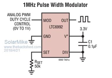 Cheers Mike |
||||
| Warpspeed Guru Joined: 09/08/2007 Location: AustraliaPosts: 4406 |
Excellent suggestion there Mike. Variable gain drive could be produced very easily from an analog multiplier chip such as an AD663. A function generator chip such as an XR2206 can produce some quite good constant amplitude sine waves. If you really prefer to have unipolar drive to the bridge, the 50Hz sinewave source could go into a voltage comparator to provide a 50Hz square wave timed to the sinewave zero crossings. That could then drive one side of the bridge directly. The other side of the bridge needs to have the phase of the PWM inverted each half cycle, and that can be done digitally with an exclusive OR gate. An interesting idea. Cheers, �Tony. |
||||
| Solar Mike Guru Joined: 08/02/2015 Location: New ZealandPosts: 1129 |
Yes that chip looks the part, its amplitude output level can also be varied over a 55db range via its AMSI dc voltage input on pin1, so a separate voltage controlled gain chip isn't required, think I will get one and try it out. 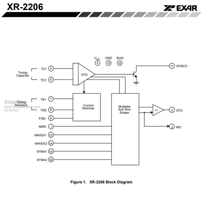 On another subject the TIP41/42 totem pole buffers for driving multiple parallel mosfets can be better replaced by the Zetex ZXGD3005E6 25V 10A gate driver chip, they are in a SOT26 package and cost about 50c each, place one directly at the gate of each mosfet, PDF Cheers Mike |
||||
| Warpspeed Guru Joined: 09/08/2007 Location: AustraliaPosts: 4406 |
I have a few of those Exar chips here, but its been a very long time since I used one for anything. They are an amazing device and one of those plus your PWM chip would have to be the simplest way to generate experimental sinewave PWM. Cheers, �Tony. |
||||
| Solar Mike Guru Joined: 08/02/2015 Location: New ZealandPosts: 1129 |
Thought I had one here too, but cannot see for looking, have ordered a couple + 2x Pwm chip on Aliexpress for $12, will plug into a breadboard when they arrive in a couple of weeks and see what they can do. People must think I'm nuts designing something using Analogue Tech... |
||||
| Warpspeed Guru Joined: 09/08/2007 Location: AustraliaPosts: 4406 |
Intersil make the ICL8038 which is a very similar chip with similar features, but I believe its not exactly the same and from memory has slightly different pin outs. I have no idea which might be better or more suitable. Probably either will work perfectly well for a project like this. Just had a look in my parts drawer, I still have five of those Exar beasts, and all with 1986 date stamps ! Golly, it must be over thirty years since I last looked at them. So as you will understand, I am a bit rusty about remembering all the exact details and specifications. But its certainly an interesting approach, and likely a fairly original too, and well worth experimenting with. That amplitude adjusting pin allows soft starting, and voltage regulation, and making it a part of a phase locked loop locked to either a crystal or to the grid would be quite easy to do as well. Cheers, �Tony. |
||||
| tinyt Guru Joined: 12/11/2017 Location: United StatesPosts: 431 |
Finally got Poida's code loaded on a NANO using an old STK500. I like the STK500 because it self powers the chip. But it couldn't drive the chip Reset down to zero. Found out that the NANO has a Reset pull-up of 1K compared to the 10K of the UNO's and MEGA's. So I just remove the 1K from the NANO. This one is after power on: 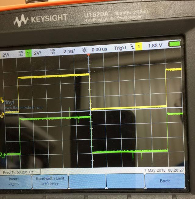 This one is immediately after the start button is pressed, SPWM is ramping up: 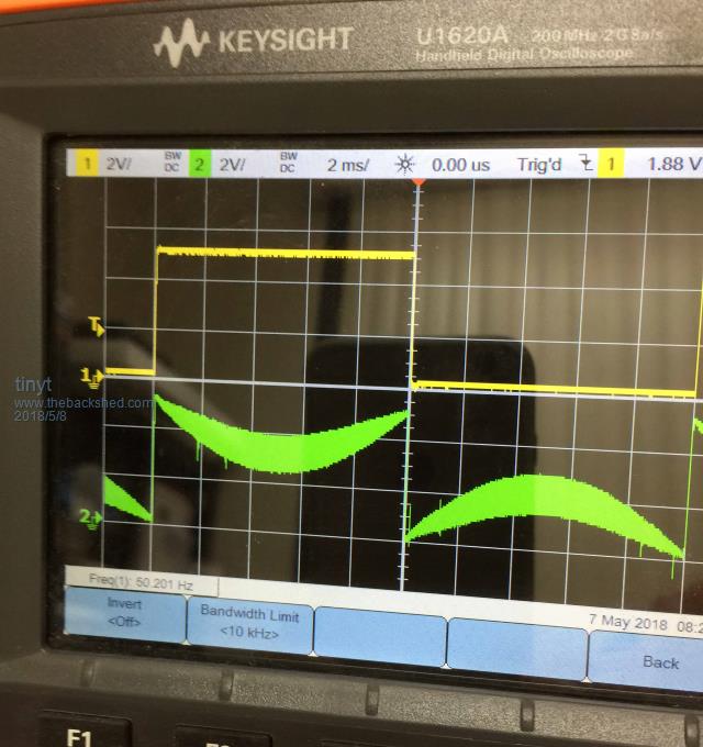 This one is when ramping is finished: 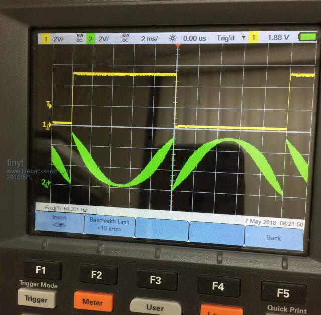 When I changed TCNT2=100; to TCNT2=120;, the scope shows Freq(1) = 57 Hz. Changing it to TCNT2=126; made the scope Freq(1) = 60 Hz. The SPWM waveform is a little messed up with this change. 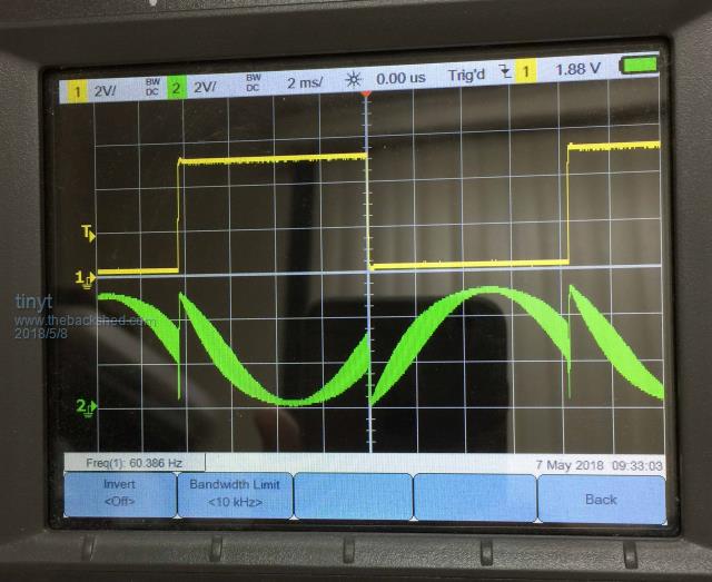 It is not my 'scope by the way, I just borrowed it. Making this change also makes the SPWM good again. #define PPWM (133333 / NPWM) // might need some fine adjustment?. |
||||
| Warpspeed Guru Joined: 09/08/2007 Location: AustraliaPosts: 4406 |
Can you do bipolar PWM ? That should produce a cleaner final output from the inverter, as there should then be minimal harmonic energy at multiples of 50Hz. Hard switching one side of the bridge at 50Hz, is a terrible idea and gives the transformer a really big sudden fright every zero crossing. Its the very strong odd harmonics of 50Hz that are likely causing some people grief with waveform kinks after each zero crossing, and wobbles on the waveform due to stray transformer resonances. Two nice clean out of phase PWM drives to the bridge should only generate harmonics above the PWM switching frequency which are much more easily removed. Cheers, �Tony. |
||||
| Solar Mike Guru Joined: 08/02/2015 Location: New ZealandPosts: 1129 |
Does this mean two chokes are required also, one on each side of the primary, or can we still get away with a single?? Cheers Mike |
||||
| Warpspeed Guru Joined: 09/08/2007 Location: AustraliaPosts: 4406 |
Oz has often told us that his high powered inverters can handle short term motor starting current peaks without the slightest sign of voltage dips or flickering lights. That makes sense, as he probably has the biggest battery in the entire world. Now that got me thinking.... Many of us are not that fortunate, and are battery challenged, and have the problem that a suddenly applied very large step load will cause the incoming dc voltage to the inverter to dip, and the inverter voltage feedback needing to compensate as quickly as it can. Oz also tells us that our big toroids have excellent voltage regulation, which is also true. Toroidal construction, and really big copper windings tends to do that. Really serious voltage surges and sags due to sudden load changes, for most of us will be caused by the input voltage to the inverter suddenly changing, not by any internal weakness of the inverter itself. So I had the idea of constantly measuring the dc input voltage to the inverter, and using that voltage measurement to control the amplitude of the generated PWM, or in my case where each of my very small inverter steps ramp up and down to follow the required sinusoidal shape. Its just straight multiplication. If the incoming voltage drops by 9%, the PWM duty cycle is instantly increased by 9% (or whatever) for the next coming mains cycle. If you do it at the zero crossings, there is no interruption to the smooth sinewave. Full input voltage correction should be very fast and achievable within 20mS even for massive swings in input voltage. And unlike a PID feedback system, it cannot become unstable or hunt. And its simple ! No more small isolation transformers and rectifiers to generate a feedback voltage. I now have this working. It covers a massive 2:1 input voltage range with ease and holds the output voltage constant well within 1% although that was not using a proper inverter but rather an analog simulated inverter. A real world Oz type inverter should easily maintain an output voltage within several percent, which is probably as good as the grid can do anyway. There is no real need for very close voltage regulation, just something that behaves as though it was fed from the worlds biggest battery. If you are writing a PWM program, give this a try. Forget voltage feedback, or any type of gradual PID ramping correction. Just measure the raw dc battery voltage coming into the control PCB before any voltage regulation, and use that to correct the overall PWM duty cycle directly. A potentiometer before the voltage sampling point can be used to tweak the nominal inverter output voltage in the normal way. It will then hold the inverter output almost constant over a very wide input voltage range, especially if there are violent voltage swings. From what I have seen so far, I am convinced I can run a large inverter straight from solar panels during the day without a battery to stabilize the inverter voltage. As far as I know this is an original idea and never been done before. Cheers, �Tony. |
||||
| Warpspeed Guru Joined: 09/08/2007 Location: AustraliaPosts: 4406 |
Two chokes would be better, but the way I would do it would be use the one choke with two windings on it. Just place one half of the winding in series with each wire to the transformer. It would be like having a centre tapped choke, and breaking the centre tap point, and inserting the transformer primary into the break. Cheers, �Tony. |
||||
| tinyt Guru Joined: 12/11/2017 Location: United StatesPosts: 431 |
Not sure how bipolar PWM looks. But I blindly modified the code as follow: //pinMode(9, OUTPUT); sbi(DDRB,DDB1); sbi(DDRB,DDB2); // ADD-MOD: enable the complement SPWM output pin .. {OCR1A = c;OCR1B = c;} // one 1/2 wave or other of 60Hz output MOD: for complementary SPWM else {OCR1A = PPWM - c;OCR1B = PPWM - c;} // MOD: for complementary SPWM pcount++; And this is what I got. 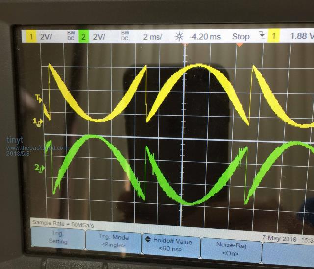 This is the best capture of OCR1B output. Most of the time it is distorted. Maybe too much code path/delay or incorrect code modification. |
||||
