
|
|
Forum Index : Electronics : Experimental sinewave inverter designs
| Author | Message | ||||
LadyN Guru Joined: 26/01/2019 Location: United StatesPosts: 408 |
I have not studied the OzInverter because there is no schematic (although I'm assuming Mike's build is inspired by OzInverter?) but I was reading that the inverter's closed form transfer function has to be linear for one to be able to control the power output using a linear modification of the PWM DC. Consider a boost convertor - I have been told that its closed form transfer function is not linear: which is why it requires a PID controller to provide error correction because a linear modification of the PWM DC is no longer userful (can cause overshoot for example). Does my understanding make sense? |
||||
| LadyN Guru Joined: 26/01/2019 Location: United StatesPosts: 408 |
One more question: So this thread is to design a homebrewn subset of a digital pure sine wave inverter ASIC like EG8010? In that case, have anyone on this thread had a look at the BTc encoding algorithm? https://www.romanblack.com/BTc_alg.htm |
||||
| Warpspeed Guru Joined: 09/08/2007 Location: AustraliaPosts: 4406 |
Feedback systems always need some kind of PID control to limit the speed and amount of feedback to have a stable closed loop system. As soon as you over correct, the system swings the other way and there can be an oscillation that then grows in amplitude. So feedback correction absolutely must be a slow gradual process. Proportional gain (P) and integral time constant (I) both need to be limited for stable operation. Think of it like this.... You are trying to adjust the water temperature in a friends shower with which you are unfamiliar. You very gradually adjust the hot tap, and the cold tap allowing time for the temperature of the water to become stable before making a further slight adjustment. If you start madly spinning taps, the temperature will swing wildly and you are going to be alternately burnt then frozen ! Correction must be slow and controlled. Likewise correcting the output voltage of an inverter must be a slow controlled process. The output voltage suddenly changes with a step load change then gradually recovers. This can cause flickering lights when the refrigerator starts up, for example. Feed forward correction is completely different to feedback correction. There will be a known relationship between the inverter dc input voltage, and the ac output voltage, derived directly from the transformer ratio. If the input voltage increases, the inverter output voltage increases in a known predictable way. So if the dc input voltage is measured, any change can be applied directly to the inverter drive waveform to compensate almost completely for any violent step load changes. Its very fast acting, and can never become unstable, and its SIMPLE. The inverter itself will provide pretty good voltage regulation. The output will fall slightly under increasing load due to conduction losses in the mosfets and transformer windings. In my case about 2V per Kw for a 92% efficient inverter, which is a pretty typical figure. So you get to choose between using overall voltage feedback or voltage feed forward correction. Very few people have tried feed forward correction in their inverters, but those that have are very satisfied with the speed of recovery from huge load changes. From zero load to 5Kw, my output voltage falls from 235v to 225v. Input voltage change from 90v dc to 180v dc produces no measurable variation in output voltage, rock solid at 235v. Very happy with that. Cheers, �Tony. |
||||
| Warpspeed Guru Joined: 09/08/2007 Location: AustraliaPosts: 4406 |
Many ways to skin a cat. Many ways to implement PWM, but its all basically just digital on off switching followed by some low pass filtering. Cheers, �Tony. |
||||
| LadyN Guru Joined: 26/01/2019 Location: United StatesPosts: 408 |
Ok, so just to confirm, this thread is to design a homebrewn subset of a digital pure sine wave inverter ASIC like EG8010? |
||||
| Warpspeed Guru Joined: 09/08/2007 Location: AustraliaPosts: 4406 |
Its a completely open ended discussion about various obscure methods ideas and and techniques to generate sine wave mains power. Not necessarily PWM and not necessarily digital and not necessarily requiring any software. Many alternative ways to go about this, with various advantages and disadvantages. What may best suit a mass produced inverter design may be much less suitable for home construction. For example, a manufacturer may spend a year getting the circuit board layout and magnetics perfected after a great number of prototypes and extensive testing. Someone obtains just the schematic, it looks simple so they just copy the circuit, join all the parts together and the thing keeps blowing up. Many people here have been through that that very painful experience. Cheers, �Tony. |
||||
| Clockmanfr Guru Joined: 23/10/2015 Location: FrancePosts: 427 |
LadyN, Regards Schematics........ From my latest Book, on the brief introduction to the OzInverter PCB's....... The New Power board has been developed using known existing technology�s and improved. It matches the new 8010 OzControl board. As I have said before my Philosophy, keep things SIMPLE, ROBUST and COST EFFECTIVE. With that in mind our Power Board, OzControl Board and the OzCooling Board PCBs are of as simple design as possible, with through hole components that are easily obtainable, the only exception is the SMD 8010 Chip on its own sub board. For builders across the World we made it a deliberate policy to make Robust boards that were also easy to assemble and easy to repair in the future. We also kept the OzControl PCB and the OzCooling PCB as single sided for home etching. The PCB�s were deliberately designed for extra-large tracks and large copper areas around component pins so to avoid substrate separation problems when repairing. All component values are printed on the PCB�s, a sort of Painting by numbers. The Power board has double copper thickness and large tracks and added copper to elevate pinch areas. What we are doing goes against the modern day concept of SMD components and Multi PCB�s that are small as possible, However this is real Power Electronics, so we have put a lot of thought in getting a good long life out of the OzInverter. Please note, and before you ask, �.. like �Oztules � I do not create schematics drawings anymore as modern PCB design software means that you can build the circuit in real space. It is very important that some of our components MUST be as close as possible to other components, and therefore a schematic is insufficient to explain this 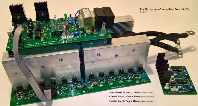 Everything is possible, just give me time. 3 HughP's 3.7m Wind T's (14 years). 5kW PV on 3 Trackers, (10 yrs). 21kW PV AC coupled SH GTI's. OzInverter created Grid. 1300ah 48v. |
||||
| tinyt Guru Joined: 12/11/2017 Location: United StatesPosts: 431 |
I think the first page of this thread here has some schematics. |
||||
| Warpspeed Guru Joined: 09/08/2007 Location: AustraliaPosts: 4406 |
You CAN do it that way, but it is never done like that by professional circuit board designers and for very good reasons, it becomes far too error prone when the circuitry becomes very large and complex. A professional design always starts out with a hand drawn circuit diagram, or series of circuit diagrams. The next step is to enter that schematic into CAD software which not only generates the familiar schematic, but does a number of other things as well. Each component is precisely defined, not just by the well known symbol on the schematic, but the footprint on the PCB, hole sizes, pad sizes, component value, function of every pin, and full characterization of the electrical characteristics. That can become quite involved for integrated circuits. Creating a new component for the component library can be very time consuming, so it can sometimes take days to create a schematic that has a lot of new or unique parts. That information is complex enough and the software smart enough that you can then do an electrical rules check, and the software will tell you if you have screwed up. Any unconnected floating pins or errors such as missing grounds or missing supplies, or accidentally linking two output pins together, will bring up error messages. From the schematic a net list will be generated. That is a list of all the nodes on the schematic that connect directly together, along with defining specific track functions such as power, ground, signal etc. Later this can be used to set different track widths. The schematic and its component libraries are also capable of full dynamic circuit simulation using "spice" or other circuit simulation, and you can look at various nodes with virtual test equipment. Its almost like building the whole thing on a breadboard and being able to view waveforms on a virtual oscilloscope, measure dc and ac voltages, view spectrums in the frequency domain, etc. All you need is a correctly entered schematic to be able to do all of that. When the schematic is known to be completely error free and passes all the required automated tests and checks, its time to start on the actual board. Major components can first be manually placed if required, and any ultra critical tracks or features then manually placed. Things like controls and indicators for example at one end of the board, location of connectors at the other end perhaps. Then you hit "auto place" and every other non critical component is automatically placed onto the board in a very logical way that ensures minimum track lengths. This takes about a couple of seconds to place a hundred or more components all very neatly placed and spaced for a pleasing result. If that all looks o/k, you then hit "auto route" and every single track on the board will be run, thin ones for signal, thicker ones for power and ground. That might take about ten to twenty seconds for a board with a hundred or more integrated circuits and several hundred minor components. And you can be absolutely certain that the circuit board will be totally error free, but only if the components specified on the schematic have been entered correctly with the correct footprints, dimensions, hole sizes and so forth. For a nicer final result, and to make it much easier to fault find later on, its possible to edit all the component designators on the PCB so that R1 is next to R2 which is next to R3 etc. And all the IC's line up U1 then U2, and so on. When the PCB component designators are edited, it automatically oes back and changes the component designator on the original schematic. If you have ever looked at a really complex motherboard that is a foot square trying to find R168, its a lot easier if the components are physically grouped in some kind of numeric sequence. Saying that schematics are no longer required is simply not true. Laying out the schematic and correctly specifying individual components is about 95% of the work. The actual physical circuit board layout is then just about totally automated these days. That is how the professionals do it. And circuitry is now so complex with tiny surface mount parts both sides, and maybe a dozen layers of tracks between, its just no longer possible to do it error free by hand. Once you have used design software like this there is no way you would ever go back to doing it any other way. Once its done, the software will also print out a full parts list again without any errors or omissions. It can even produce a three dimensional picture of the final board so you can see what its going to look like from any angle. Amazing stuff ! And absolutely EVERYTHING relies completely on the original schematic you entered. Cheers, �Tony. |
||||
| LadyN Guru Joined: 26/01/2019 Location: United StatesPosts: 408 |
Tony, my uncle used to work at a PCB factory when they still made PCBs in California and it was exactly what you describe. That said, I remember seeing some RF engineers working directly at a PCB factory floor because the simualtors did not get the results exact due to trace impedance and reflections. I was pretty yong back then and probably am recollecting the terms they used incorrectly, but the schematic was just a starting point. Before my asthmaticus episodes became more frequent, I used to make double side FR4 copper clad PCBs and tin them with my uncle. Drilling was the most painful part because of my acute myopia. It's funny but I got interested in electronics because I cannot hang out with my peers outside and must instead spend my time mostly indoors. Power electronics is also probably like the RF design: schematic are just a starting point. So I see why the inverter gurus here skip the whole schematic part and jump directly to PCB. I remember a few cases where the engineers would disable design review checks in their routing software because a trace or two would need to be routed just right and my uncle's shop did not have cutting edge machines to get those tight traces reliably. That said, newbies like myself would really REALLY appreciate schematics for sure. PCBs are better than nothing but it's just that newbies like myself would spend time reversing the PCB to arrive at the schematic. @Clockmanfr: I am super excited to see you're writing a book and that too a second edition! CONGRATUALTIONS! 2 questions: 1. have you considered putting in schematics in your second edition? 2. why don't you sell an electronic copy of your second edition? I won't be surprised if a significant portion of your costs are in the paper, ink and shipping. If you are concerned about people pirating your electronic copy, are you not concerned someone might scan in the 80 or so pages anyways? I wont be surprised if you sold more electronic copies in a month than hardcover in a year. |
||||
| Warpspeed Guru Joined: 09/08/2007 Location: AustraliaPosts: 4406 |
High frequency power electronics share many of the same problems of RF design, in that physical layout and component placement can be critical to success. A schematic might suggest that just just joining up all the components any old way that is convenient should work just fine, but sadly that can lead to difficulties. Using a proven circuit board such as Clockmans gets you off to a very good start, but there can also be difficulties beyond the circuit board with grounding and magnetics design, as well as cooling that can come into it as well. The higher the power level the more difficult it can all become, especially for a novice. And some of the concepts can be difficult to explain in a simple manner. Cheers, �Tony. |
||||
| Clockmanfr Guru Joined: 23/10/2015 Location: FrancePosts: 427 |
LadyN, 1. I know that 'TinyT' did the schematics and they seemed okay. Putting them in the 2nd edition?..... Maybe 'Tinyt' might approve of them being used, I just haven't got time to do them myself. Note, I spotted a couple of missing bits when I first looked at those schematics first thing this morning. Electronic copy, yea hmm, I have seen scams and work sold onto others with out acknowledgements, that were generously given by others. So not at present. If they scan it they scan it, but each page is copyrighted and my books have official ISBN numbers, look on Amazon for ISBN 978-0-9935903-0-6 And besides so much easier when making stuff to have a A4 size booklet with large colour photos that explain things more than words can sometimes. And to get coffee mug stains on, like my ever faithfull 'Hugh Piggotts' 'Make a Wind Turbine' A4 booklet. Warpspeed. I am not against schematics I used to work with them in the late 1970's, Heathkit days, gosh everything was so clunky. In the mid 1980's I did some prototyping stuff with DOS software, I hated rat nests, and operating the software became a whole profession on its own. After that I stuck with my CAD and Micro engineering profession and work with mechanical manipulation of metals from 40mm to 4 micron. In 2015 I purchased some 'Target' PCB software, it was all I could find at the time for a reasonable cost that would integrate with my CAD, and just got on with it to create the OInverter PCB's. Funny to see that nothing has really changed in the in-between years, and the pin layouts are still in divisions of an Inch and more jargon introduced. And yes, the 2nd edition will be more specific, about How to, where and how things are placed and fitted in regards cooling, cable layouts, positioning of main components etc etc. And the Don't stray from the road that works sentences.! Everything is possible, just give me time. 3 HughP's 3.7m Wind T's (14 years). 5kW PV on 3 Trackers, (10 yrs). 21kW PV AC coupled SH GTI's. OzInverter created Grid. 1300ah 48v. |
||||
| Warpspeed Guru Joined: 09/08/2007 Location: AustraliaPosts: 4406 |
Yup, all good stuff Clockman. Cheers, �Tony. |
||||
| tinyt Guru Joined: 12/11/2017 Location: United StatesPosts: 431 |
I only translated into schematic form what all of you great pioneers did. It is free for all to use for whatever purpose. You can correct and re-draw it using your own schematic capture software. If you post the needed corrections, I can revise the schematic and post it. |
||||
| LadyN Guru Joined: 26/01/2019 Location: United StatesPosts: 408 |
Ugh, I wish I was on this board a 18 months ago when you were working on the first stage as that's EXACTLY what I want to do. I completely see value in all the 3 stages and will be replicating your discoveries. Should I create a new thread to document my learning from you and others on the forum so as not to derail this thread? |
||||
| Warpspeed Guru Joined: 09/08/2007 Location: AustraliaPosts: 4406 |
I have changed my thinking on some of the details since then, but the basic idea remains exactly the same. An inverter that runs DIRECT off the solar panels during the day, without requiring a battery or a solar controller. That will definitely give you the greatest bang for each dollar spent. Then at night run off grid power. The night time load is never much, just the refrigerator, a few lights, and that is about all. The battery came very last, and is really uneconomic because of the high cost of the cells which have an unknown life span. I will be lucky to break even over ten years, but its just something I always wanted to do, so eventually did it. New thread sounds like an excellent idea. Cheers, �Tony. |
||||
| LadyN Guru Joined: 26/01/2019 Location: United StatesPosts: 408 |
YES! I did want to confirm: with your stage one idea we don't have to pick and choose between either PV output or rectified dc grid power right? We have the best of both worlds. Here, solar energy is used to supplement the rectified dc grid and then the sum of both is used to drive an inverter? I wanted to ensure I have this exactly right yes! Done: https://www.thebackshed.com/forum/forum_posts.asp?TID=11087&PN=1 |
||||
| Clockmanfr Guru Joined: 23/10/2015 Location: FrancePosts: 427 |
Hi tinyt, Thanks for your offer, that's great. I have actually finished that chapter, but it would be nice to add schematics of the Power Board and the OzControl board, so I will add/push another page in. I get stuff printed in colour so colour tracks, if that helps. I will look closely at your schematics. typical ..... My Inkjet printer has just run out at the same time as My black& White laser printer has just run out of toner. And just as I was doing the USA chapter with the modified 60HZ OzControl board etch masks. Trouble is the roads around here are covered in snow with nice freezing ice underneath, and its hilly around here. Its an hour drive to a supermarket that might be open and might stock. Everything is possible, just give me time. 3 HughP's 3.7m Wind T's (14 years). 5kW PV on 3 Trackers, (10 yrs). 21kW PV AC coupled SH GTI's. OzInverter created Grid. 1300ah 48v. |
||||
| Clockmanfr Guru Joined: 23/10/2015 Location: FrancePosts: 427 |
Sorry Warpspeed for messing up your thread. Tinyt, Obvoiusly you are 4 FETs with 4008. I have checked the 2nd and 3rd schematic you originally posted. Both seem okay... for the power board I will put a note that 'check the IDC cable is correct' and probably those 2 10nf 250v suppression caps that go to the boards fixing holes. The control board needs those decouples 10uf and 100n caps, bypass/alongside the 1k resistor that comes from the ON/off switch to ground. Pin 6 is super sensitive to switch contact bounce, and the cable sensitive to other nearby cables and can/could pick up parasitic's. Here is the OzControl board for the US at 60HZ. 2019-01-31_203046_60hzOzCntl15.pdf and the etch masks and silk screen... 2019-01-31_203942_No260hzOzCntrl.pdf Everything is possible, just give me time. 3 HughP's 3.7m Wind T's (14 years). 5kW PV on 3 Trackers, (10 yrs). 21kW PV AC coupled SH GTI's. OzInverter created Grid. 1300ah 48v. |
||||
| LadyN Guru Joined: 26/01/2019 Location: United StatesPosts: 408 |
Thank you very much Clockmanfr for including schematics! You mentioned tinyt might have omitted few components but he released a few updates to his schematics. Are the omitted components you noticed last time back in there now? |
||||
