Notice. New forum software under development. It's going to miss a few functions and look a bit ugly for a while, but I'm working on it full time now as the old forum was too unstable. Couple days, all good. If you notice any issues, please contact me.
wiseguy Guru Joined: 21/06/2018 Location: AustraliaPosts: 995
Posted: 02:44pm 11 Nov 2021
Copy link to clipboard
Print this post
Can you post a picture of the inverter and control board ? Is it a commercially made unit ? What is the input voltage ?
I found this a bit confusing "Some background first, I have been using inverter (2000W, high frequency) for several months powered by AGM batteries, server PSU, and DC-DC converter without any issues running with and without loads"
It said a lot but I would like you to spell it out a bit more to ensure I have a better feel of what you are running & doing.
It could be that the lower impedance of the LiPo could drive much more current into an issue whereas a higher impedance supply was not able to create enough destructive current. Also, in my limited experience with LiPos, they typically seem to have & hold a bit higher terminal voltage for longer than their lead acid counterparts - this could have exacerbated any issues.
With no load to the inverter, turning it off and back on within say 10 seconds may not have been enough time for the main capacitors to discharge fully. You didn't mention a pre-charge when you turned it back on the second time within ~10 seconds when it went bang.
The "charging" current doesn't make sense unless maybe the back emf of the transformer/choke discharged their stored energy back into the battery, or the ultra high discharge current when it went bang totally overloaded the BMS system and it just reported crap - I am sure that during the explosion the current was well in excess of the 47A it reported for max discharge, I would guess well in excess of 200A for a second or two.
A bit of a description of how you carry out your pre-charge would be useful too. It is possible that you may even work out yourself what might have gone wrong in answering these queries. Sorry to hear of your dead inverter - they aren't very pretty when they go bang and it scares the crap out of you If at first you dont succeed, I suggest you avoid sky diving.... Cheers Mike
analog8484 Regular Member Joined: 11/11/2021 Location: United StatesPosts: 89
Posted: 06:24pm 11 Nov 2021
Copy link to clipboard
Print this post
@wiseguy, thank you for your comments.
The inverter is a commercial unit with 12VDC nominal input and 240VAC/60Hz nominal output rated for 2000W continuous/4000W peak. Actual input was about 13.6VDC in the test. Regarding pre-charge, I have a fuse/switch on the positive line between the battery and inverter and I used a resistor (10R/100W) to pre-charge the inverter until the voltage on the inverter input terminals reached the same voltage as the battery before closing the fuse/switch. The pre-charge resistor was left connected. So, I don't think the inverter input capacitors were discharged when I restarted the inverter.
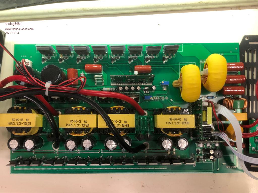
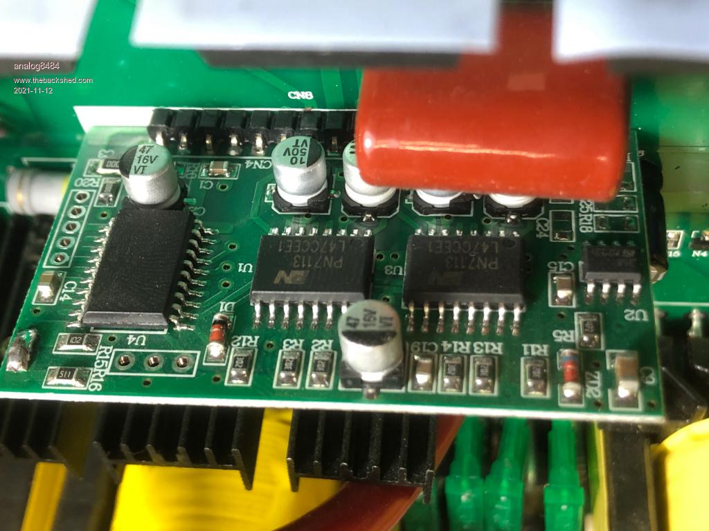
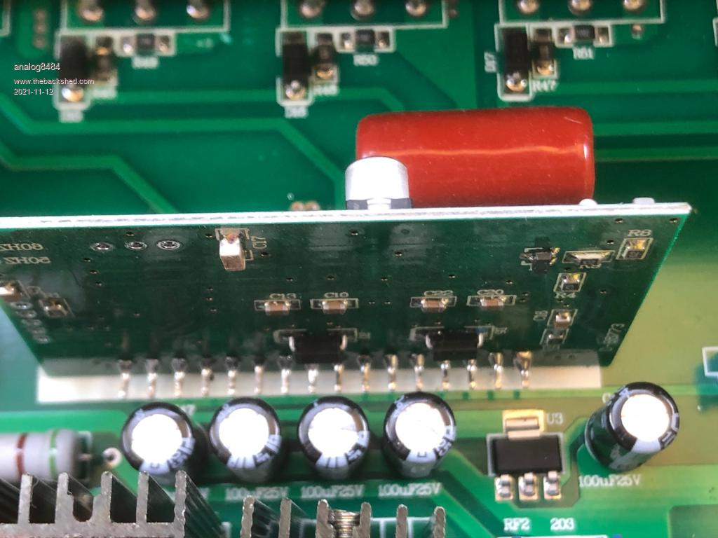
Below are some pictures of the inverter.
Overview:
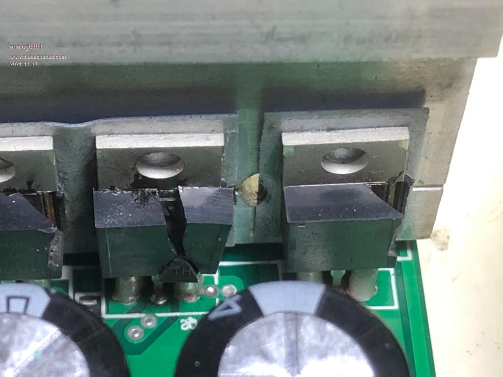
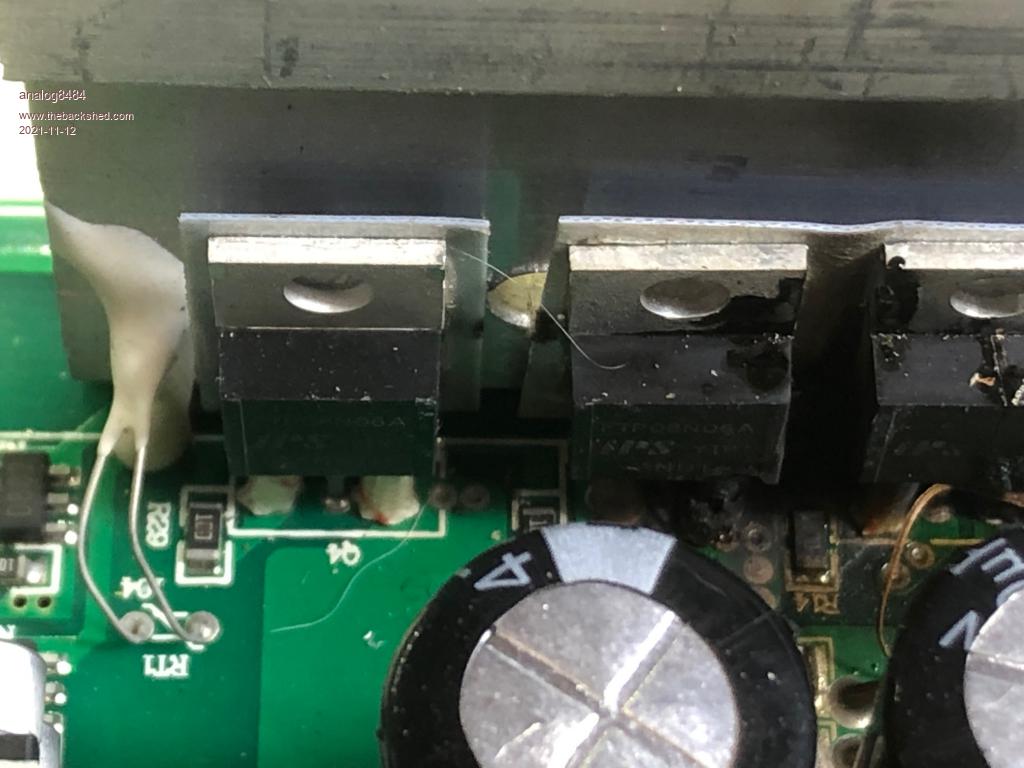
Blown input MOSFET's:
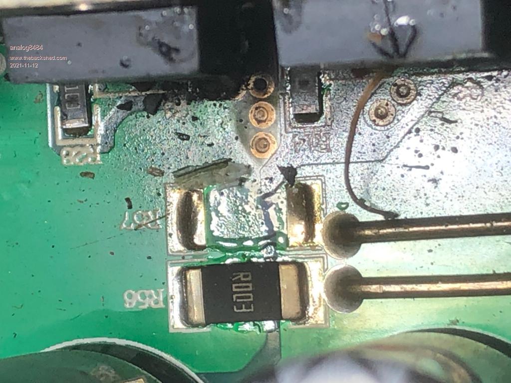
I believe these are input current sense resistors due to the low value and one was blown off.
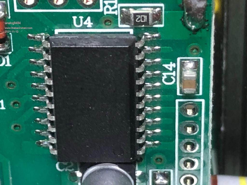
Control Board that looks similar to egs002:
Close up of the controller with no markings that I suspect is an eg8010 clone:
Let me know you want more info or photos. Edited 2021-11-12 04:36 by analog8484
wiseguy Guru Joined: 21/06/2018 Location: AustraliaPosts: 995
Posted: 01:06am 12 Nov 2021
Copy link to clipboard
Print this post
I must say the little sinewave PWM PCB looks a lot like the EGS002 PCB - in engineering we call it being "inspired" by someone elses design - the word copy never occurs.
Your inverter is quite different to the types mostly encountered on this forum. It first converts the input nominal 12V to ~ 350 -400V and then chops up this voltage with HF variable PWM to create a sinewave which travels through the big yellow inductors and is filtered further by the 3 red poly capacitors to create a fairly smooth AC output.
Due to the amount of trouble this type of inverter has, especially its inability to drive higher start up currents required by many types of load we went in a different direction.
The majority of experience here is to run from mostly 48V and a few 24V systems and we create the variable PWM and apply this to a big choke & toroidal transformer system that has plenty of overload capability to start up big loads with ease.
Your inverter failure might just be one of those things that if you replace all the dead FETs with at least IRF3205 or stronger IRF3206 or strongest overkill IRFB7534 types it could work or it could go bang again as there may be a fault also on the secondary side which could be FETs Diodes even failed poly capacitors that caused the original "bang" and reflected all the damage onto the primary side.
Depending on your level of expertise and patience it might be a cinch or a nightmare to make it work again - cant be much more help from here, cheers and good luck ! if you have a local "technical" friend I would take advantage of their help if offered.If at first you dont succeed, I suggest you avoid sky diving.... Cheers Mike
analog8484 Regular Member Joined: 11/11/2021 Location: United StatesPosts: 89
Posted: 02:36am 12 Nov 2021
Copy link to clipboard
Print this post
Actually, this is what I thought happened since the "egs002"-like card drives the secondary/output stage. The primary/input stage H-bridge is actually driven by an sg2525 based card near the output filters.
I am trying to better understand how such a catastrophic failure could happen without any load. I don't feel comfortable just replacing the failed components without better understanding. Can you elaborate more on how a secondary/output stage failure could cause catastrophic primary/input stage damage *without* any load?
BTW, I totally agree that low frequency inverters have much better surge power. In fact, I have one and I tested it with the LFP battery without any issue but it's too heavy for the portable application I have. So, I am using high frequency inverters as a compromise. Edited 2021-11-12 12:38 by analog8484
Revlac Guru Joined: 31/12/2016 Location: AustraliaPosts: 961
Posted: 02:43am 12 Nov 2021
Copy link to clipboard
Print this post
@analog8484 The EGS card appears to be driving the high voltage output side,(Correct me if I'm wrong) so much the same as the low frequency drive just has a high voltage buss so no need for a step up transformer, still has choke and output filter. As there was no load attached the IGBT's gate drive and EGS might still be ok, but check it to be sure.
Its the converter that has stuffed up, and its quit typical that the high voltage rectifier mosfets are shorted as well, when the low voltage mosfets are blown to pieces. Why the rectifier and low voltage mosfets have blown? one possibility, I should say CHAIN of Events, If there was some sort of inductive spike on the battery supply to the inverter, this could go through the little transformers to be converted to a high voltage spike shorting the rectifier, this could overload the little transformer and blowup the low voltage fets, when the fets blowup they cannot be producing any square wave or enough power through the little transformers to blow the rectifiers to pieces, so no visible damage to them, have seen this before. This could be caused by interrupted signals from the power supply and low voltage bridge driver and the result is the same. Its worth checking all associated drive components etc and repair where necessary. The exact cause of this inverters destruction I don't know, just the likely problems. Whether you get it working or not, it is always a learning experiences, and that experience is often handy for other things.
Ah, I was a bit late to the party.Cheers Aaron Off The Grid
InPhase Senior Member Joined: 15/12/2020 Location: United StatesPosts: 178
Posted: 02:44am 12 Nov 2021
Copy link to clipboard
Print this post
The side that blew up is the push-pull DC-DC converter. Each of those transformers has a center tap connected to battery positive. The ends of each primary are alternately pulled to ground by the FETs, each transformer having four FETs controlling it. Often all those FETs are driven by a transistor buffer from a TL494 or equivalent PWM chip. You should snip the FETs off and scope the gate pins to see what the signal looks like. The egs002 looking circuit controls the upper 8 FETs that don't appear smoked.
analog8484 Regular Member Joined: 11/11/2021 Location: United StatesPosts: 89
Posted: 11:00pm 12 Nov 2021
Copy link to clipboard
Print this post
Yes, that's why I thought posting in this forum could be helpful based on the eg8010/egs002 knowledge I have seen in past posts.
Thank you for the helpful scenario. The sequence seems quite plausible. Can you given an example cause of battery inductive spike? Without load? Also, what's the appropriate protection for the rectifier diodes against voltage spikes? I checked the inverter diodes and they are rated for 600V.
Do you think a high voltage side IGBT short caused by something like the eg8010 shoot-through bug could cause similar destruction of the low voltage side MOSFET's?
Based on your explanation, I wonder if the following scenario could be plausible:
* Inverter started without load so the high voltage side capacitors and the low voltage side capacitors were all full.
* Inverter was turned off without load and the battery was connected so the capacitors remained near-full.
* Inverter was restarted shortly after and the eg8010 shoot through bug is triggered.
* IGBT's shorted out by high current from the near-full high voltage side capacitors.
* The high voltage side capacitors drained leading to high current draw through the transformers.
* The high current draw refills the high voltage side capacitors but also shorts out the rectifier diodes due to over-voltage? or over-current? The low voltage side MOSFET's short out subsequently.
* The low voltage side MOSFET's stop switching but the high voltage side capacitors are full and the rectifier diodes are shorted.
* Current from high voltage side capacitors flows back through the transformers back to the battery. This leads to the BMS recording a very high charging current peak.
Please let me know what you think of the scenario.
That's exactly how I feel. I want to have better understanding of the problem to help decide if I should repair or get another one of the same inverter model or look for another one that addresses any likely design deficiencies that contributed to the severity of the failure.
analog8484 Regular Member Joined: 11/11/2021 Location: United StatesPosts: 89
Posted: 11:11pm 12 Nov 2021
Copy link to clipboard
Print this post
Thank you for the info. I checked and the input side is indeed a push-pull DC-DC converter driven by an SG3525. I can also confirm the controller has voltage and current sensing via sense resistors so I would think it should have shutoff the MOSFET's before shorting out?
I
johnmc Senior Member Joined: 21/01/2011 Location: AustraliaPosts: 282
Posted: 12:32am 13 Nov 2021
Copy link to clipboard
Print this post
Good Day All I have blown up a few inverters for unknown reasons.
I have found that you MUST have, only solid connections battery supplied directly to the inverter. No other connection between battery and Inverter.
To supply charge to the battery, use a stainless steel bolt and washers on the charger to battery connection, ( as per directions that Solar Mike quoted a long time ago on this forum) this I believe, stops unwanted spikes to the inverter.
I have not had a inverter failure "blowup" since adopting the above .
Cheers johnjohnmc
Revlac Guru Joined: 31/12/2016 Location: AustraliaPosts: 961
Posted: 11:48am 13 Nov 2021
Copy link to clipboard
Print this post
Ok, example's that I know and had experience with, that could cause a spike, the battery has some other appliance or inverter connected to the same battery that this inverter is connected to and running, if a sudden load is switched on or off or some sort of sudden short making a rapid change in voltage that the inverter can't adjust to, can cause a voltage spike. A very common scenario is a bad contact somewhere between the battery and the inverter, over time I had a main switch develop a bad contact, I have taken out a SMPS this way as well. I see John, has shared some experience with this as well.
I don't know any way to stop a spike getting to the rectifier, even a 650v diode can short, raising the voltage of the diode much higher will probably shift the damage to other parts and possibly more damage.
Once you fix it all up it may not even happen again for years.
I see you have thought of a few scenario's that I haven't thought of,
Its possible, but I think the result would be blown IGBT on the output, It looks like (total of 8), 2 per leg, the capacitors should have enough energy storage to blow them to bits....unless they are very tough, then I guess it could brake elsewhere at the weakest parts. There are a few other ways, thing's things can go here, but haven't worked that out yet, I'm not an EE. I haven't had that much trouble with the EG8010, had some issues with noise on the 5v line when using pin 6 for on off, (think it was pin 6, can't find the diagram, being a while since I worked on it) issue was fixed with some capacitors, details elsewhere.
Not sold on the 8010 bug. Not familiar with that particular board in the photo could have some differences in it. Its likely interrupted during restart, I think Wiseguy pointed to this earlier. Switch bounce can do things but is usually fixed in commercial gear.....we hope.
Caps where full, but with the rectifier shorted, the caps would be drained into the winding of the transformer and would be DC, this would be shorted by the winding, I guess this would present a load for a moment.
Some times a BMS might not always show the current correctly, I assume its due to its sampling rate, one I have is like that, but the clamp meter shows it better.
Trying to work out the exact scenario can be difficult to even futile, so wouldn't put too much effort in to that. Hope some of this makes sense, I sort of got lost trying to work some of this out as its not on the table in front of me. So this my attempt trying to explain it. What it boils down to is An interruption of power or to control system signal, and the result is destruction.
Best to do your fault finding and double check the component values if you missed anything it will destruct again. Make sure all connections, switches, circuit breakers and fuse holders are in perfect working order, and this kind of blowup might not happen again, no grantee.Cheers Aaron Off The Grid
wiseguy Guru Joined: 21/06/2018 Location: AustraliaPosts: 995
Posted: 01:55pm 13 Nov 2021
Copy link to clipboard
Print this post
With regard to how a problem on the secondary can take out the primary. Suppose a shoot through of some sort occurred in the output section, the FET/IGBT(s) is taken out and essentially becomes a short across the secondary of the 4 x up converters (shoot through at 400V is pretty much always destruction). Have you measured across all the output devices - my guess is that they might be ok, shoot through is not proved yet to be the culprit but if it was, at least some of the output devices would usually be damaged/shorted.
If output devices are dead, the poor primary converters are now trying to run into a shorted secondary load, huge currents now flow from the Battery into the primary FETs and within milliseconds there are bits of plastic and smoke flying around the place.
The impedance of the primary has to be really low by design as the supply voltage is only 12V nominal and currents of ~ 170A+ are required for ~2KW+ and if we believe their 4kW surge rating 340A+ are required. As there are usually no current limiting parts - including fuses - unless there is a whole bunch of 30A blade fuses in parallel - (normally they are the only parts left intact whilst most other bits are turned into vaporized metal and plastic) its not pretty when things go wrong.
The secondary diodes and the primary mosfets both have a lot of stress placed on them at startup as the 350/400V capacitors are usually discharged and it relies I believe on the 2 x R003 resistors in parallel on only one of the 4 boost converters which is no doubt used to control the SG3525? switching to limit the throughput power of all the converters and just hope they are all sharing nicely.
Some of these inverters are of Asian origin and are just built to a price (a whole lot less than you paid) and are sometimes copies of reasonable equipment, but in cost cutting and copying sometimes subtle design features are compromised leaving them prone to self destruction with no obvious reason.
Summary: if the output devices - including rectifiers polycarbonates and mosfet/igbts are all ok then it is likely that only the primary boost converters failed for some reason. Your challenge is now to find all the dead bits including any FET drive buffers from the SG3526, remove and replace them all without causing further damage. Access to a good solder sucker would be very handy and if used properly it will help minimise further damage.
Then when finished you can either try a current limited 12V supply (no load to the output) or whistle a happy tune whilst you connect it back to the LIPO vaporiser.......
I consider myself to be fairly competent to tackle a repair like that but don't take 45+ years of experience for granted - this may not be an easy repair for someone with relatively limited experience & equipment. You might be lucky but remember even when built as designed and without abuse or even a load it still went bang. There are ways of supplying low currents and control voltages and "fooling" circuits into run mode & minimise chances of damage before applying lots of current - but that's beyond what I'm prepared to try to describe in detail here.
Lastly don't think of no load on the inverter as zero load for the components, as when starting from cold the "load" is at least the boost capacitors rapidly being charged up.
I cant really dress this up nicely as it is what it is ! Maybe the gods will be kind to you and it will be just some routine parts replacements and it will run again, who knows?If at first you dont succeed, I suggest you avoid sky diving.... Cheers Mike
analog8484 Regular Member Joined: 11/11/2021 Location: United StatesPosts: 89
Posted: 06:51pm 13 Nov 2021
Copy link to clipboard
Print this post
Thank you for the info. I used a torque wrench to tighten down all connections and there was nothing besides a fuse/switch between the inverter and battery. Just curious, have you experienced inverter failure without load?
analog8484 Regular Member Joined: 11/11/2021 Location: United StatesPosts: 89
Posted: 07:01pm 13 Nov 2021
Copy link to clipboard
Print this post
That makes sense but I am not sure it applies to my situation since I tightened all connections with a torque wrench, didn't have anything else connected to the battery and didn't switch on/off anything else.
That's a good point. That would be another way to short out the output IGBT's and trigger the failure sequence.
analog8484 Regular Member Joined: 11/11/2021 Location: United StatesPosts: 89
Posted: 07:48pm 13 Nov 2021
Copy link to clipboard
Print this post
The output IGBT's all appear to be shorted out based on what I can measure but there is no visible damage to them. Same with the rectifier diodes.
That's a great description of what I observed. I still wonder why the input stage over-current/short circuit protection didn't really help. I do remember hearing the buzzer going off as the explosions happened. So, the inverter definitely detected a fault condition.
Yes, the LFP battery used has internal resistance < 20mR. I think that contributed to the severity of the failure event. My AGM battery's internal resistance is more than 10x?
Actually, there are 8 30A fuses and they are all fine. So, I think the short circuit current was very high but didn't last long enough to burn out the fuses.
Yes, it looks that way. Definitely a design compromise. Are you aware of a high frequency inverter with more robust design?
The output stage is definitely all shorted out. Thanks to your great insights I am now more convinced that the failure started in the output stage (eg8010 bug or control signal interruption/noise).
I usually use a bench supply limited to 5A for such testing/repair. However, I am now going through a warranty repair/replacement claim so I don't want to make any changes to the board at this point. If I get to keep it later then I may attempt repair more for the learning experience.
I can see that. I wonder if that happens on warm restarts as well.
Thanks for all your help.
Godoh Guru Joined: 26/09/2020 Location: AustraliaPosts: 378
Posted: 09:10pm 13 Nov 2021
Copy link to clipboard
Print this post
There are a few things that can blow inverters up. Poor solder connections are a big one. The last photo you put up of the IC u2 looks to have been soldered very lightly. If you lose drive to mosfets they go bang, if one goes bang they almost always all decide to join the party. Anything that is plugged in can cause problems too. the 8010/egs002 board is one point where things can go pear shaped. Any other chips that are plugged in can also be points of faulure. Also there is always the question of whether the assembly line had good static electricity protections. Mosfets are easily damaged by static, and it can take a while to show up. good luck with fixing it. Make sure that you change any drivers for the mosfets. Pete
Godoh Guru Joined: 26/09/2020 Location: AustraliaPosts: 378
Posted: 09:13pm 13 Nov 2021
Copy link to clipboard
Print this post
Sorry I said the chip was U2 but it is in fact U4 when i looked again. Pete
wiseguy Guru Joined: 21/06/2018 Location: AustraliaPosts: 995
Posted: 09:52pm 13 Nov 2021
Copy link to clipboard
Print this post
My testing usually starts at 30mA at 12V and depending on results will eventually be set higher than that in stages as required. But that would also be after I have applied current limited voltages etc to the secondary first to check that it appears to work ok. At my age I try to avoid the sudden loud bangs and stressful stuff as it might not be good for the ol ticker.....
I am assuming that the inverter has an on off switch of sorts (not one that carries 350+ Amps) the on off switch usually just shuts off the boost converter driver section. The 12V input capacitors remain charged but the output ones will usually lose charge fairly quickly.
Ok so the outputs are shorted - so now we know how/why the primary died. After another look I can now see the bunch of green fuses - totally missed them until prompted by your comments. Warranty replacement would be the best outcome not sure what you have over there, we have a "consumer affairs" government office here where if suppliers won't come to the party they will take up your fight with the importers/sellers and can fine them heavily if they wont comply. We also have a statutory warranty scheme that says goods sold must be fit for purpose and last a reasonable time commensurate with purchase price. A 12 month warranty just scares off the faint hearted, the statutory warranty can be up to 5+ years - it is not well advertised though, maybe you guys have a similar scheme ?If at first you dont succeed, I suggest you avoid sky diving.... Cheers Mike
analog8484 Regular Member Joined: 11/11/2021 Location: United StatesPosts: 89
Posted: 06:55pm 14 Nov 2021
Copy link to clipboard
Print this post
Thanks for the info. I did pick at the legs of the eg8010-like and sg3525 controllers and they seemed solid but various manufacturing deficiencies are certainly another possible failure cause. I do wonder if the shoot through problem had been ongoing and stressed/degraded the MOSFET's over time. One potential reason why the problem didn't kill the inverter before could be that the previous DC power sources used couldn't provide the destructive current surge that LFP battery could with its much lower internal resistance.
analog8484 Regular Member Joined: 11/11/2021 Location: United StatesPosts: 89
Posted: 07:42pm 14 Nov 2021
Copy link to clipboard
Print this post
I don't know if the inverter has soft-start on the primary and/or the secondary stages which should help minimize risk of inrush related damage at turn on. My understanding is that both eg8010 and sg3525 can do soft-start with minimal add-on circuitry.
My experience with larger inverters is relatively short and frankly I am a bit surprised with their general reliability. I had thought such inverters have been around for decades and must be mature commodity that's relatively reliable/safe like other larger appliances (e.g. microwave, induction cooker). So far, they appear to be more like temperamental science projects.
Based on my findings so far, I plan to check in future inverters beyond typical features: * Shoot-through protection * Soft-start * Comprehensive over-current sensing/protection
That's my hope. My inverter actually has an 18-month warranty while many other low cost inverters have only 12-month warranty.
wiseguy Guru Joined: 21/06/2018 Location: AustraliaPosts: 995
Posted: 12:11am 15 Nov 2021
Copy link to clipboard
Print this post
My only experience with HF inverters are limited to Xantrex and Meanwell. Meanwell is one of the better Asian manufacturer & suppliers of inverters and they do stand behind their warranties.
Xantrex have a very good name and are a bit more expensive usually than the rest. I would probably go Xantrex for best reliability and support.
I would not be scared off though just by the origins of Meawell either, if they have a similar unit at half the price it all depends on how you trade off reliability and inconvenience if it fails against purchase price etc.
Others may have different or more recent & relevant opinions too - my first hand experience is now 5+ years out of date. Edited 2021-11-15 16:40 by wiseguyIf at first you dont succeed, I suggest you avoid sky diving.... Cheers Mike