Notice. New forum software under development. It's going to miss a few functions and look a bit ugly for a while, but I'm working on it full time now as the old forum was too unstable. Couple days, all good. If you notice any issues, please contact me.
wiseguy Guru Joined: 21/06/2018 Location: AustraliaPosts: 1001
Posted: 08:16am 01 Oct 2018
Copy link to clipboard
Print this post
ATTENTION PLEASE My posting about an alternative drive scheme should not be taken as a construction project - it should be treated only as a curiosity - something to discuss and think about, but I strongly advise against anyone implementing it at this stage.
Despite the results showing promise on a test bed, until I have actually constructed it and proven the design it should be treated as a no go.
Although I eluded to no switching transitions at the zero crossings I believe the 8010's deadtime implementation will introduce such a transition in some of the drive waveforms it is of little consequence, but this is early days of implementation and testing.
Gaspo - if it works well, there is no reason it could not be made as part of the adapter board - that is why I took the discrete transistor approach - but it is much too early for this discussion in my opinion. Edited by wiseguy 2018-10-02If at first you dont succeed, I suggest you avoid sky diving.... Cheers Mike
Tinker Guru Joined: 07/11/2007 Location: AustraliaPosts: 1904
Posted: 09:37am 01 Oct 2018
Copy link to clipboard
Print this post
Wiseguy, using a small transformer to do the testing is something I did with my inverters. Yes it works fine and the one I used had a 26V & 230v winding. This produced the 230V for the little feedback transformer. But, as you say, its no substitute for a big toroid. Me thinks its high time now to cut your teeth winding one of those . This is, after all, how most of the inverter builders here started their project. You are doing yours back to front .
Warpspeed, thanks for that wound on static screen explanation as applied to toroids. I did not appreciate that this is what happens, thinking if the Aerosharp people wind it on there must have been a reason. That is why I re used that screen foil.
Do you think I would have done better by winding instead some inert thick tape to increase the distance between primary and secondary layers? Some builders are doing that by using insulated welding cable. Just curious since I'm happy with the wave form, having almost no zero crossing distortion.Klaus
wiseguy Guru Joined: 21/06/2018 Location: AustraliaPosts: 1001
Posted: 09:52am 01 Oct 2018
Copy link to clipboard
Print this post
Ok Klaus touche. I know I'm doing it backwards but I was too chicken to start with the transformer. I thought if I psyched myself up by having some control and FET Power boards lying around enticing me, it would help motivate me - I am not looking forward to the winding process. I also wasn't sure of the DC supply I would use to start with, but 48V nominal (the lowest I would consider) seems well accepted here.
As soon as I finish the PCB's and send them off then the hard work begins I guess.If at first you dont succeed, I suggest you avoid sky diving.... Cheers Mike
Tinker Guru Joined: 07/11/2007 Location: AustraliaPosts: 1904
Posted: 09:53am 01 Oct 2018
Copy link to clipboard
Print this post
Well now that you have stimulated my few remaining working neurons I had this thought:
Wrap a bare copper strip around the outer circumference of the toroid so it looks like wearing a belt. To this are soldered insulated 20mm copper foil strips which are just long enough to make one overlapping turn. I suppose they could be bare copper as long as the small overlap area is very well insulated later. This is to avoid a short turn, obviously. Keep soldering strips on until it looks the toroid is wearing a grass skirt. Wrap them around the core, they will overlap in the hole but are side by side at the strip. Insulate this lot and add the primary winding.
Would this work? it should not take any more hole room than wrapping the continuous insulated copper strip did.Klaus
Tinker Guru Joined: 07/11/2007 Location: AustraliaPosts: 1904
Posted: 10:02am 01 Oct 2018
Copy link to clipboard
Print this post
It only 'looks' like hard work. By the time you wound your second, third or fourth toroid its like a walk in the park. Just read all the early posts of the various inverter builds here and you get plenty of ideas how to go about it. Then pick what suits you Remember the number of turns thing *is* important and you can't bread board that. Once that primary is wound on top of the secondary it would be a pain to add or remove turns from the latter .Klaus
wiseguy Guru Joined: 21/06/2018 Location: AustraliaPosts: 1001
Posted: 10:08am 01 Oct 2018
Copy link to clipboard
Print this post
I'm thinking I could pay you to take a walk in the park for me......... If at first you dont succeed, I suggest you avoid sky diving.... Cheers Mike
Warpspeed Guru Joined: 09/08/2007 Location: AustraliaPosts: 4406
Posted: 03:39pm 01 Oct 2018
Copy link to clipboard
Print this post
Its basically a primary to secondary capacitance coupling problem, so a very thick layer of insulation should certainly help. Also using thick round wire for the primary such as heavy welding cable that only comes close to the secondary where it just touches may work reasonably well. As would a twisted round bundle of wires in heat shrink.
I think this is probably why not everyone is plagued by the kink problem, more by good luck than anything else many here have escaped the kink problem, while some others have it to some degree.
The worst way to do it might be to wind with a handful of individual unconstrained wires splayed so they are in pretty much intimate contact with the secondary. Each pass through the hole counts as one turn, primary and secondary can have some physical separation within the hole without causing any problems, provided there is enough room to do it.
An electrostatic screen needs to completely cover the secondary, with preferably a slight overlap, but obviously without producing a shorted turn at the overlap point.
Your suggested method should work, but its labor intensive and a bit fiddly, and would never be considered for a mass produced commercial toroidal transformer.
But for us it would certainly be a very practical and doable solution, and well worth trying.
Cheers, �Tony.
gaspo Regular Member Joined: 25/06/2018 Location: AustraliaPosts: 61
Posted: 07:02am 13 Oct 2018
Copy link to clipboard
Print this post
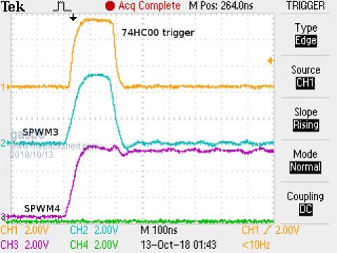
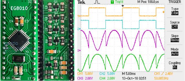
I have now received some adapter boards so I assembled one and tested it.
First I performed the same tests as Wiseguy and Poida did with unmodified adapter board and have observed the same ~200ns shoot through on SPWM pins when coming out of IFB or TFB error condition.
With the new adapter board the problem did not occur so it looks like the output transistor do their job.
The reference voltage with TL431 works fine as well producing 4.96V on the VREF pin.
Clockmanfr Guru Joined: 23/10/2015 Location: FrancePosts: 427
Posted: 08:14am 13 Oct 2018
Copy link to clipboard
Print this post
Very nicely done 'gaspo'
Everything is possible, just give me time.
3 HughP's 3.7m Wind T's (14 years). 5kW PV on 3 Trackers, (10 yrs). 21kW PV AC coupled SH GTI's. OzInverter created Grid. 1300ah 48v.
tinyt Guru Joined: 12/11/2017 Location: United StatesPosts: 431
Posted: 08:23am 13 Oct 2018
Copy link to clipboard
Print this post
I second that. Also excellent presentation gaspo.Edited by tinyt 2018-10-14
wiseguy Guru Joined: 21/06/2018 Location: AustraliaPosts: 1001
Posted: 08:56am 13 Oct 2018
Copy link to clipboard
Print this post
Well done Gaspo, good to see the positive results from your efforts.
If at first you dont succeed, I suggest you avoid sky diving.... Cheers Mike
Tinker Guru Joined: 07/11/2007 Location: AustraliaPosts: 1904
Posted: 09:20am 13 Oct 2018
Copy link to clipboard
Print this post
Very neat Gaspo, you must have excellent eyesight and robotic controlled hands to solder those tiny parts . Let me know when you want to test it on my 2.5KW inverter. I will be away for the first half of next week.Klaus
Warpspeed Guru Joined: 09/08/2007 Location: AustraliaPosts: 4406
Posted: 12:41pm 13 Oct 2018
Copy link to clipboard
Print this post
That is a pretty clever bit of circuitry. Well done !Cheers, �Tony.
gaspo Regular Member Joined: 25/06/2018 Location: AustraliaPosts: 61
Posted: 01:05pm 13 Oct 2018
Copy link to clipboard
Print this post
Thank you. Working with SMDs is just practice but you need steady hands. My eyesight is not what it used to be so I use 5 dioptre desktop magnifier lamp. Tinker, I'll let you know via PM to find suitable time to test.Edited by gaspo 2018-10-15
gaspo Regular Member Joined: 25/06/2018 Location: AustraliaPosts: 61
Posted: 03:18pm 11 Nov 2018
Copy link to clipboard
Print this post
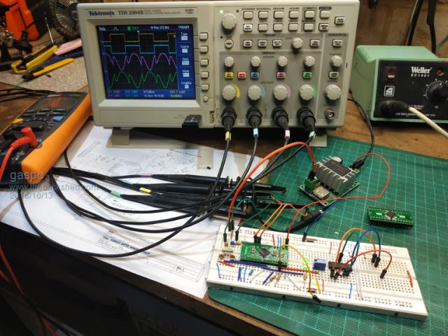
Went today to Tinker's place to try this adapter board on his nice test rig. That's Wiseguy's design from few pages back. Well, it seems to work quite well. Max load we tried was about 2.4KW.
Edited by gaspo 2018-11-13
nickskethisniks Guru Joined: 17/10/2017 Location: BelgiumPosts: 419
Posted: 07:13am 12 Nov 2018
Copy link to clipboard
Print this post
Hi, can I buy it somewhere, or is it better tot sent the gerbers tot China?
Tinker Guru Joined: 07/11/2007 Location: AustraliaPosts: 1904
Posted: 11:04am 12 Nov 2018
Copy link to clipboard
Print this post
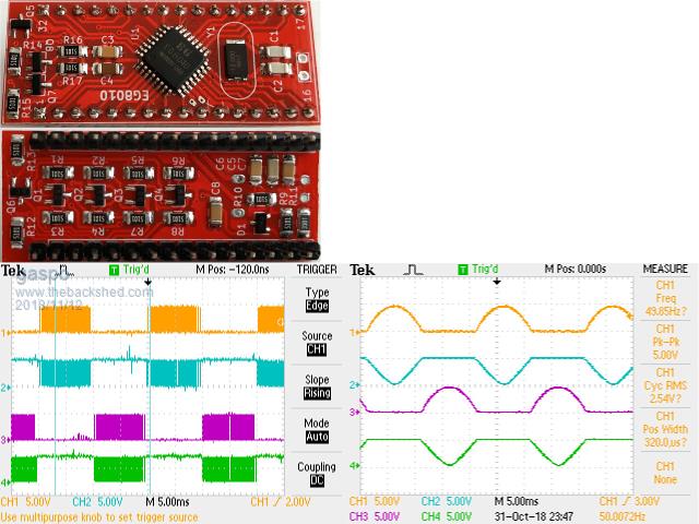
A follow up on gaspo's post above, yes we tested at 2.4KW load but with only using 4 off HY4008's! They certainly are tough.
So, today I did a few more tests with wiseguy's alternate output board.
The idle current was exactly the same with the original and wiseguy's EG8010 board.
I did notice a small difference with high load current, wiseguy's board drawing around 0.5Amp or so less (out of 56Amp) under load. But that needs more testing to confirm.
Next I tested the 4 HY4008's to their limit .
The idea was to see the heat sink temperature difference (if any) for the two EG8010 boards. So I cranked up the load to 2500W which the 4 x HY4008's took fine, stop inverter and re soft start under full load and all. I let it run until the NTC turned the fan on via the EG8010 control.
Then I switched the inverter off (the fan keeps on running of course) until the fan stopped. Immediately, the inverter was soft started again and a timer started.
The timer was stopped when the fan came on again and the time recorded.
So the heat sink temperature was cycled between fan on and fan off times to give a reasonable bench mark without using fancy thermocouples etc.
When I did that test on the other EG8010 board, before I could complete it, the HY4008's quit - it had enough.
So it appears a 4 mosfet inverter can handle 2.5KW for perhaps 10 minutes or so on a decent size heat sink. This may be a useful bench mark to newbie builders.
I'll repeat that test with a 2KW load soon.
Interesting was the failure: its the tiny internal wires in the HY4008 body that give up. Not the full length legs nor the screw terminal connectors which coped with the 56Amps. The drain connection on the board looked like it was about to unsolder itself at the mosfet that actually popped open - though 3 out of the 4 mosfets were kaputt. Warpspeed once suggested to beef this drain track up with a solder tag, good idea IMO. No problem with the source pin as this current goes via the heat sink.
Oh, that mad clamping bar worked a treat . Klaus
wiseguy Guru Joined: 21/06/2018 Location: AustraliaPosts: 1001
Posted: 02:37pm 12 Nov 2018
Copy link to clipboard
Print this post
I just noticed the post of Gaspos you referred to - somehow I missed it. I was unaware of the boards existence, so it appears Gaspo was playing with a hardware version whilst Poida was coding the alternate symmetrical drive.
I really cannot fathom why the EG8010 guys did not elect to use this scheme as standard for their unipolar drive - it is uncomplicated elegant efficient quiet and least likely to have any bad behaviour issues.
I had stalled on my controller board as I was totally unimpressed with the general behaviour of the EG8010 with or without cross conduction transistors. I was adding so many bandaids & gating around it that I started (begrudgingly) looking for a micro-controller solution.
At about this point Poida & Gaspo were perfecting a great Arduino solution that would easily adapt the alternate scheme.
Poida can you please confirm that the, USB Nano V3.0 ATmega328 16M 5V Micro-controller CH340G board For Arduino Module will work with your code?
Tinker I am impressed with your pioneering attitude/spirit but my advice would be to be patient a little longer whilst the Arduino code is massaged further and perhaps we can soon do an Arduino plug in replacement board running the alternate drive scheme - I am confident it will be better than the EG8010 hardware version. Are you saying that you only used 1 FET per Leg of the Bridge - 4 in total not 4 per leg ?
2.4kW with 4 FETs sounds a bit light on, whilst the average current doesn't look too bad from the DC source the actual peak currents during switching can/will be much higher. Edited by wiseguy 2018-11-14If at first you dont succeed, I suggest you avoid sky diving.... Cheers Mike
Tinker Guru Joined: 07/11/2007 Location: AustraliaPosts: 1904
Posted: 01:08pm 13 Nov 2018
Copy link to clipboard
Print this post
Yes, just 4 Mosfets in total. I do that in case one or more blows while experimenting. 2.4KW is a decent load (50+A) and replacing 4 mosfets is cheaper than 12 or more
i have written elsewhere what happens if just 4 mosfets are used for too long, I suggested 10-15 min at that load. Klaus
analog8484 Regular Member Joined: 11/11/2021 Location: United StatesPosts: 89
Posted: 07:06am 11 Nov 2021
Copy link to clipboard
Print this post
Hi All, I am a new member who found this great thread through web search for answers on why my inverter exploded. The thread is old but I am hoping the veterans on the forum can help me understand what may have happened to my inverter.
Some background first, I have been using inverter (2000W, high frequency) for several months powered by AGM batteries, server PSU, and DC-DC converter without any issues running with and without loads. Then I tried it with the new LiFePo4 batteries I got recently. I was aware of the low internal resistance of LiFePo4 batteries so I was careful in pre-charging the inverter before turning it on without any load. The inverter turned on just fine and ran for a few minutes without load then I wanted to get a better idea of the startup current draw with a clamp meter. So, I turned the inverter off without any load, added the clamp meter and waited for maybe 10 seconds then turned it back on. Then the inverter failed catastrophically with loud explosions and I quickly turned it off. I have seen inverter failures before but never like this. After the smoke cleared, literally, I checked the battery and it was fine. The BMS recorded a 47A *discharging* current peak which makes sense given the likely short that happened but more baffling is that it also recorded a 213A *charging* current peak. I don't have a clear understanding how that could have happened.
I opened up the inverter and found all input MOSFET's were shorted and half had exploded/cracked with burn marks. The high frequency transformer output rectifier diodes and output IGBT's were also shorted but none showed visible damage. All the capacitors seemed fine. So, it seems like over-current/short-circuit (rather than over-voltage) was the main cause of failure?
Based on what I have read in this thread I believe it could be due to something like the eg8010 bug that causes shoot-through. I checked the inverter driver card and it looks very similar to the egs002 with the same number of pins but uses a controller with no markings with a different chip package form factor from the eg8010. I am wondering if it could be an eg8010 clone? Is anyone aware of such a thing? Also, there are no transistors on the card to prevent cross-conduction like on the egs002.
One thing I am not sure about is whether the eg8010 bug could cause whole system short in a high frequency inverter. Your thoughts are welcome.
Ultimately, I would like to know if there is anything in the test process that I can improve to avoid such catastrophic failure in the future.


 . This is, after all, how most of the inverter builders here started their project.