
|
|
Forum Index : Electronics : Random Unexplained Inverter Failures
| Author | Message | ||||
| Tinker Guru Joined: 07/11/2007 Location: AustraliaPosts: 1904 |
Some remarks on my recycled current transformer. Yes, I know, I should have remembered the importance of that resistor but after having learned about this back in the 1970's and since then never dealt with another current transformer I might be forgiven to have forgotten that. Warp's not so kind remark about a certain schematic reminded me  . .Anyway, that seems to have been the shut down problem with my 6KW inverter, which would shut down occasionally when ridiculously small loads, like a LED magnifying light, were switched on. This is not happening now after I soldered a 100W resistor across the rectifier pins after the C/T output. Now, you engineers like to do things in a very scientific way but mine is a more hands on way. I did not care about the 60Hz rating at all. The set up is measuring the output at the rectifier with a digital meter by powering a wire through the C/t hole that made a shortened turn across the 7.5V power secondary winding of a transformer I had handy. I slowly increased the voltage at this transformers primary with my Variac. This way I could easily dial up 40A AC through the wire in the C/T. The digital meter showed 1V at 20A which was plenty as the SCR trips at considerable less than this. Keep in mind, this C/T is used to trigger a SCR and *not* to measure current per se. So all I do is set the desired trip current through the C/T with the variac and then adjust the 2k trimpot until the SCR trips. Do that a few times (inverter needs to be re set every time it trips) to make sure it works as expected. I have no problem with passing more than 20A through the C/t hole as required for my 6KW inverter - I set that to about 30A to cater for momentary loads. Keep in mind the continuous load is a fair bit under 20A 99% of the time. Anyway, it works for me. Wiseguy, you can read in my "inverter #4" pages how I pre set the VFB input. All that is then required is to fine tune the trimpot once the inverter is running to set the desired AC voltage. I do not bother to find out how far I could adjust it, I think oztules did write about that some time ago. I use the little 240V-12V transformer to sample the AC, have also tried a dedicated feedback winding on my little experimental inverter's toroid which works the same, it just required different resistor values. One unexpected thing that happens with my inverter is, the output voltage rises about 4-5V under load. So I pre set it 5V below my desired running voltage and it sits there in idle. Another thing I noticed, the non saturating choke I made from re cycled Aerosharp C cores did lower the standby power (as drawn from the battery) of my 6KW inverter to 29W from the mid 30's when it had just the ferrite E core choke. Klaus |
||||
| Warpspeed Guru Joined: 09/08/2007 Location: AustraliaPosts: 4406 |
Its all sounding very good Klaus, and so it should after all the work you have put into it. Quite happy to continue making constructive suggestions that people may find helpful. But criticizing a circuit that "appears" to work, and that everyone is quite happy with the way it is, only provokes a lot of anger. I would rather avoid that. Cheers, ĀTony. |
||||
| wiseguy Guru Joined: 21/06/2018 Location: AustraliaPosts: 1017 |
Tinker I did not explain properly what I wanted to know. I am aware that after a number of retries to start the 8010 will lock itself out requiring a power down event to restart it. I know the VFB too low or high can do this. Does any other condition cause this lockout needing a power removal and restart? Does the lockout condition ever occur once the units are set up and running ok ? If the answer is yes can you please describe the method you use for a complete power down and restart. The voltage rising at the output under load is slightly peculiar. It is possible the 5V logic supply line which has the reference voltage pin of the 8010 tied to it could change slightly, 5V in 240V is around a 2% change. The TL431 on the Gaspos adaptor board might just fix that? The penalty is isolating pin 17 of the adaptor board & running a wire to the 12V supply from it. I started to describe a setup using a Variac & toroid & your current transformer etc and then stopped myself & deleted it - I knew you didnt need spoon feeding to suss this out - you would figure out 3 ways & then choose the easiest. If at first you dont succeed, I suggest you avoid sky diving.... Cheers Mike |
||||
| Tinker Guru Joined: 07/11/2007 Location: AustraliaPosts: 1904 |
I would prefer to be shown why certain things should be done differently, its a great way to learn on this forum. But I do pick and choose just which ideas I adapt and which are either beyond my understanding or know how to implement. If I were to follow every suggestion made here I doubt I'd have 4 working inverters by now  . .You are doing a great job with your explanations, easy to read and lacking heaps of nerdy acronyms that myself and, perhaps, many here have no idea what they mean. This is a hint to one particular poster BTW  , keep it readable for the average Joe here who is smart enough to build a working inverter but may lack the formal technical education to design one from scratch. , keep it readable for the average Joe here who is smart enough to build a working inverter but may lack the formal technical education to design one from scratch. Klaus |
||||
| Tinker Guru Joined: 07/11/2007 Location: AustraliaPosts: 1904 |
You may double check with the 8010 specs but I think all the shut downs do that if not re set in a short time. I have experience with over current trip (C/T problems) occurring at evenings and by the time I get to the inverter it had locked off. Cure is to open both DC battery circuit breakers, one in each battery lead (not the inverters internal ones) and then use a suitable resistor to short the DC connection until the flashing fault light goes off due lack of 5V. Then press reset. Then turn on negative C/B, this slow charges the caps as the positive C/B has a permanent 33R resistor across its terminals. Once the green light (battery voltage) comes on I turn on the positive breaker (shorting that resistor) then press reset again to clear the fault light(from low voltage). This Rst might have to be repeated if the status light still flashes. Once only the green light is on I switch the unit on (pin 6). Several seconds nothing happens then the unit soft starts and the status light is steady on. I did play with TFB by heating the NTC sensor once beyond where it turns the fan on. This then shuts the inverter down too, I did not wait long enough to see where it needed a total restart since I used a soldering iron , not a controlled heat source on the sensor. There was never a lock out for no apparent reason, always the flashing status light sequence shows what happened. Klaus |
||||
| Warpspeed Guru Joined: 09/08/2007 Location: AustraliaPosts: 4406 |
Yes, but you are a true gentleman Klaus. Cheers, ĀTony. |
||||
| wiseguy Guru Joined: 21/06/2018 Location: AustraliaPosts: 1017 |
Thank you Klaus - If I am the guilty party of using nerdy acronyms I will try to mend my ways. No disrespect but initially I thought there was a bunch of real techies on the forum to be dealing with this stuff. It is more like a group of over average achievers some from relatively non technical backgrounds who have done a great job in making these things work. I have never spoken to Oztules but I can see he was/is a master of many skills & trades and a great driving force & resource for the project. If at first you dont succeed, I suggest you avoid sky diving.... Cheers Mike |
||||
| gaspo Regular Member Joined: 25/06/2018 Location: AustraliaPosts: 61 |
Enclosed are the latest adapter board files. I've added couple of small pads for easier soldering of jumper wires for those wishing to use the off-board crystal. Let me know if you see any issues with the board otherwise I'm going to submit the order on Monday. 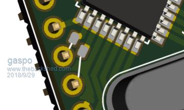 2018-09-29_232947_EG8010-adapter-files.zip |
||||
| wiseguy Guru Joined: 21/06/2018 Location: AustraliaPosts: 1017 |
Hi Gaspo Looking good but maybe I am tired confused etc it appears that J2 has crossed up pins 3&4 and pins 5&6. In my view for instance EG8010 pin 27 should still connect to Adaptor pin 27 after passing through gating transistor Q4 ? Not a big deal but C4 doesn't have a polarity marked so I'm assuming its a multilyer ceramic ? Everything else looks ok to my tired eyes. If at first you dont succeed, I suggest you avoid sky diving.... Cheers Mike |
||||
| gaspo Regular Member Joined: 25/06/2018 Location: AustraliaPosts: 61 |
Good find Wiseguy, looks like my eyes were crossed while drawing up the schematic. I fixed that and updated the board tracks accordingly. Yes, the C4 is multi-layer ceramic. 2018-09-30_025610_EG8010-adapter-files.zip |
||||
renewableMark Guru Joined: 09/12/2017 Location: AustraliaPosts: 1678 |
Warp, you know how much of an electronics mastermind I am, can you elaborate on this? Cheers Caveman Mark Off grid eastern Melb |
||||
Madness Guru Joined: 08/10/2011 Location: AustraliaPosts: 2498 |
Mark there is a 120 Ohm Burden Resistor across the Diodes for the current transformer. There are only 10 types of people in the world: those who understand binary, and those who don't. |
||||
| wiseguy Guru Joined: 21/06/2018 Location: AustraliaPosts: 1017 |
Let me apologise in advance for the technical nature of this post but I wanted to share my experiments and results with other readers and the technical bits are unavoidable. I finally had some time to play a bit more. Before I created my control PCB I wanted to test my theory about Symmetrical drive - and I like it a lot more more than I thought I would. Essentially I took the 4 SPWM outputs after the 4 cross conduction transistors that then drive the H bridge and added some more signal steering transistors to achieve the signal trains that I wanted. Initially I created some equations of what I wanted and then got to the part of implementing the function in gates (logic not Bill). I didn't like the gates result (or Bills either....), then I added some diode steering and transistors and also didn't like that, finally I decided that if they can implement logic using a few discrete transistors to prevent cross conduction, I can do the same and add a few more to achieve what I wanted. Without further ado please see the attached page for the scheme. 2018-10-01_125853_New_Symmetry_Drive.pdf 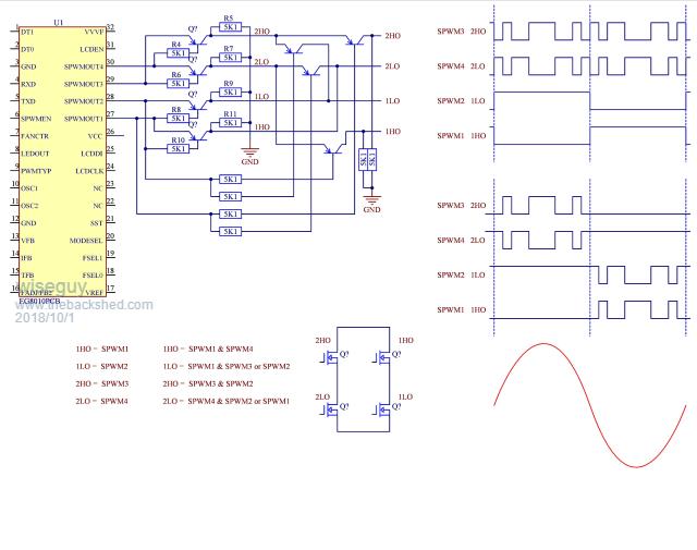 The 4 waveforms at the upper RHS are the waveforms currently driving the inverter. The 4 waveforms directly under those are my version of how I wanted it to work. All the waveforms shown are for the gates of the FETs The gating with those few transistors seriously did my head in for a few hours but the end result is very satisfying. If you look at the new waveforms each PWM starts as it finishes and remains at that level until it has to PWM again. The upper Fets never pull high for the fundamental only the side doing the HF PWM. If you look at all the transitions going on in the upper group of waveforms at the 0, 180 & 360 degrees it is real busy. Now look at what happens as you go through those same points with the lower waveforms - yep thats right nothing. Essentially we drive the transformer primary up to the peak and back to zero then we reverse the primary (in effect) and use the same waveform again but we swapped sides of the H to do it. I think it looks elegant and avoids a lot of unnecessary transitions & complication in the switching. Advantages:(maybe others undiscovered?) 1) Pimary is not transitioning from zero to 50V for each alternate half cycle. 2) No busy transitioning of all 4 waveforms at each 180 degrees zero crossing. 3) The LHS and RHS share the power switching (and generated heat) equally 4) The two upper waveforms (1H0 & 2H0 )are no longer driven during the fundamental part 5) Both sides of the transformer start from zero (Batt Negative) and end at zero for each alternate half cycle. And a few pictures of it working - yes I have finally made an inverter - of sorts. I grabbed the nearest transformer and drove it with the waveform - surprisingly I didnt get 240V only about 150V. Warning Do not try this at home. The result 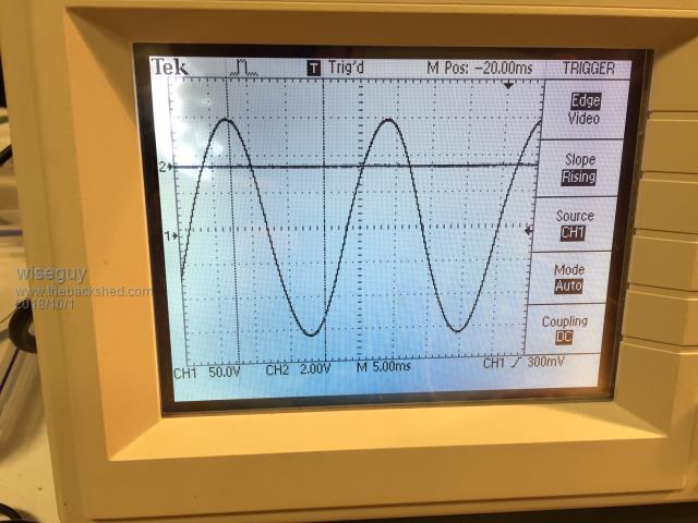 Driving the Pos peaks 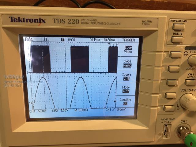 Driving the Neg peaks 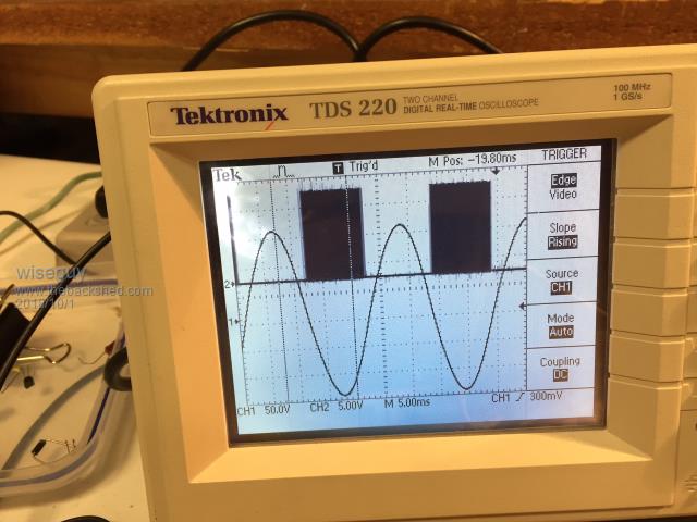 The mess that made it possible 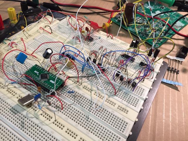 The PCB at the rear has 4 x TO220 mosfets mounted on it for convenience. The two IC's on the upper RHS of the breadboard are the two IRF2110's. Breadboarding this stuff is not advisable - only for those who get it. Thats all for now. If at first you dont succeed, I suggest you avoid sky diving.... Cheers Mike |
||||
| Warpspeed Guru Joined: 09/08/2007 Location: AustraliaPosts: 4406 |
Great stuff Mike. That should get rid of the zero crossing kinks without adding an electrostatic screen to the toroid. Would probably work best with a choke in each side of the primary, but should be o/k with just one choke. Cheers, ĀTony. |
||||
| Solar Mike Guru Joined: 08/02/2015 Location: New ZealandPosts: 1129 |
Cool, would do anyone's head in working out the logic, can you explain how this would be better than moving to a bi-polar modulation scheme, that the 8010 can be switched to. Cheers Mike |
||||
| wiseguy Guru Joined: 21/06/2018 Location: AustraliaPosts: 1017 |
Mike , Ive got a better plan can you explain why a bipolar modulation scheme is better that tnis scheme and its advantages over this scheme - I thought I listed some advantages with the posting ? I would have thought that having double the switching losses and associated heat generated would be high on the list. Not needing 2 voltage feedbacks & associated circuitry for each half of the generated wave also figures. The fact that unipolar is time tested as the choice for all high power units being discussed on this forum. The fact that I have spent a considerable amount of my time testing the EG8010 and working out how to avoid its buggy behaviour to date and I dont want to go to a bipolar scheme I personally dont like, and then try to figure out what new bugs are lurking for the unwary. This scheme is really just a minor rearrangement of the current inverter scheme being used but I think a little tidier. Im happy to use my scheme as presented - I also totally support anyone wanting to use a bipolar scheme. Warp thanks for elaborating on why the 50V transitions on the primary are undesirable - there is no sign of the crossover distortion in my scheme - but its still got to prove itself at higher power levels - not on this breadboard ! If at first you dont succeed, I suggest you avoid sky diving.... Cheers Mike |
||||
| Warpspeed Guru Joined: 09/08/2007 Location: AustraliaPosts: 4406 |
Several different ways to do PWM with ac voltage, each has various advantages and disadvantages. Unipolar only requires two of the four mosfets to switch really fast, but has the disadvantage of very abruptly switching the transformer at the zero crossings with full battery voltage at 50Hz, where the polarity at the secondary has to change over. Capacitive coupling between primary and secondary, which can sometimes be especially high for a toroidal winding can couple a large transient into the secondary at the zero crossings. That could be mitigated by placing an electrostatic screen between primary and secondary, but that becomes rather more difficult to do effectively with a toroid. Pretty easy with a conventional E/I transformer though, but that is not what most of us have. This coupled transient is what causes the notorious kink in the output waveform after one or both zero crossings that some people are seeing. Continuous and simultaneous true bipolar sine wave drive to both ends of the transformer primary solves all of those kink problems, but then you require all four mosfets to be continuously PWM'd which should not really be a problem. The whole thing needs to be thought right through, and various decisions made as to the PWM mode of operation, and the design of the transformer, and the advantages and disadvantages weighed. Plenty of combinations are possible. Unipolar drive and an unscreened toroid may not always be a happy combination, although it can work quite well. The kink may be truly awful or hardly visible at all. It depends mainly on the primary secondary coupling capacitance. Cheers, ĀTony. |
||||
| renewableMark Guru Joined: 09/12/2017 Location: AustraliaPosts: 1678 |
Why not just re use the bronze coloured foil tape from the aerosharp? That shouldn't be any harder than winding wire. Cheers Caveman Mark Off grid eastern Melb |
||||
| Warpspeed Guru Joined: 09/08/2007 Location: AustraliaPosts: 4406 |
Here is a thought experiment for you guys. On top of the primary of your toroid you wind an electrostatic screen with insulated copper foil. Because its a toroidal shape, for practical reasons the foil cannot be made very wide. You cannot wrap 300mm wide foil around a toroid !!! So you fit on 18 turns of suitably narrow insulated foil, and ground one end of that. Then on top of that you wind (say) a hypothetical 18 turn primary. The screen is going to do absolutely zero because when you switch 48v across the primary, there is going to be an identical 48v developed across the 18 turns of the screen, and that is going to couple straight into the secondary just the same (or probably worse !) than having no screen at all. An electrostatic screen really must have only one turn around the core, and that is just not possible to do on a toroidal core. Its dead easy to fit a one turn screen on an E/I transformer with flat foil the same with as the transformer bobbin. Putting an effective screen on a torodal core that is actually going to work and do something worthwhile, is not that simple. Cheers, ĀTony. |
||||
| gaspo Regular Member Joined: 25/06/2018 Location: AustraliaPosts: 61 |
Would the symmetrical arrangement work with the existing inverters if 8010 adapter board contained the 8 transistors circuitry shown? |
||||
