
|
|
Forum Index : Electronics : BMS Revisited
| Author | Message | ||||
| Warpspeed Guru Joined: 09/08/2007 Location: AustraliaPosts: 4406 |
I hoped to avoid it too, by feeding my cell selecting shift register into a decoder chip that has an output enable. So the routine went, disable all multiplexer drive outputs, shift in the new next cell selecting data, enable multiplex drive to the selected cell, rinse and repeat for the next cell in sequence. Was supposed to be completely idiot proof and immune to blow ups. But when the software goes totally rogue, things happen randomly and very fast. These optically coupled mosfet switches take some significant time to turn on, powered only by a few miserable wimpy photons to charge up the gate capacitance. And significant time to turn off, by some multi meg ohm ultra slow gate to source bleeder resistance. If the software goes to Hell, things are happening very fast and much to my surprise can totally defeat the idiot proof master plan. Simultaneous turn on which I believed could never occur, does in fact happen, and with enough fault current to blow multiple fuses. Current limiting resistors sound like an excellent idea. I chose fuses, which arguably may or may not be superior. Any series impedance and shunt capacitance in the voltage measurement circuit is likely to have some effect on the initial voltage measurement. It may require some time allowance to stabilize down to single digit millivolt reading accuracy and resolution. Its all a design tradeoff of course. Just needs to be very cynically thought right through, with due respect for the esteemed Mr Murphy's Law. Cheers, ĀTony. |
||||
| Solar Mike Guru Joined: 08/02/2015 Location: New ZealandPosts: 1123 |
Latest Update: Decided to use serial to parallel adapters for all the slow IO data. As Warp hinted earlier using these opto-switches for getting the battery cell analog voltages is a slow process; at approx 10ms to read each cell, direct high speed IO isn't required and I would have to use one of the 28 or 40 pin CPU's. Placed the output relays and fan control on an external non-isolated 12v PSU so have added opto-couplers to those outputs, this gives more options for direct drain pull-down to battery 0v if a relay is not required. I have a generic 1-Wire module designed for the data network so have added a connection to allow the BMS to talk to a central cpu for aggregation of alarms and site status. PCB will require some mods. Circuit: 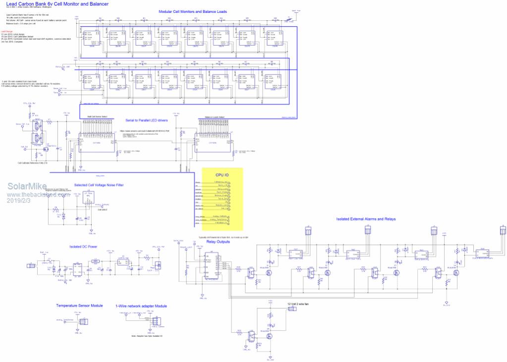 2019-02-03_210725_BMS_DriverSchematic.pdf Cheers Mike |
||||
| Solar Mike Guru Joined: 08/02/2015 Location: New ZealandPosts: 1123 |
Forgot to mention, the issue of measuring cell voltages when a balance load operation maybe concurrent for that or adjacent cells, upsetting the readings due to voltage drops in the cables is easily solved by bringing out the enable wire from each serial led chip. Immediately prior to taking a voltage reading, the "Load" CAT4016 is pulsed off, so cable voltage drops can be ignored. Mike |
||||
| Warpspeed Guru Joined: 09/08/2007 Location: AustraliaPosts: 4406 |
Great stuff Mike, its extremely difficult to keep a system like this simple. By its very nature there are going to be a huge number of connections and parts required. Here is the cell monitoring business end of my BMS. 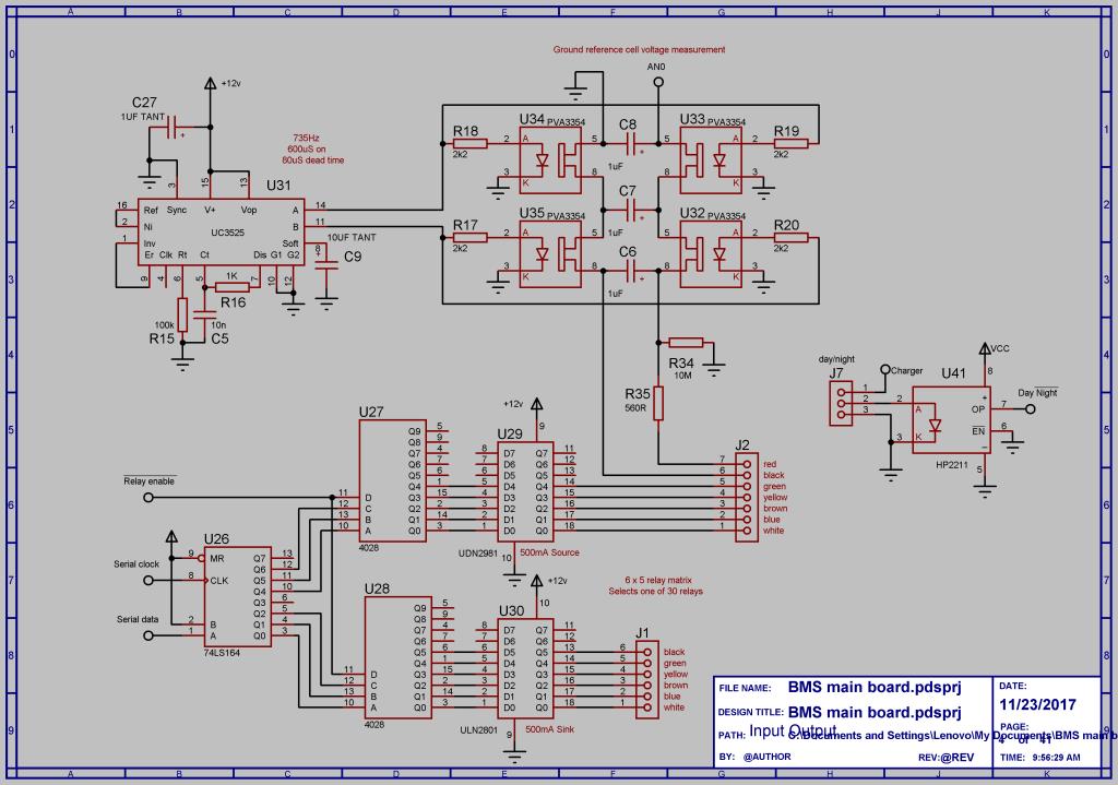 It was originally designed to switch multiplexed relays, but I gave up on that idea and now use LAA127 mosfet switches. These are robust enough to be protected by a fuse, but they are slow. U32, U33, U34, and U35 are my flying capacitor voltage isolator that use PVA3354 switches which have a higher on resistance, but are faster than the LAA127's. Trial and error and some experimentation determined the values of C6, C7 and C8, and the switching frequency and dead time. It works well over about a 20:1 frequency range but starts to go to hell with either very low or very high switching rates. R34 and R35 compensate for the off leakage current through U32 and U33. I found that if I connected a single lithium cell direct to this, with one side grounded, it worked fine with the voltage at AN0 equal to the measured cell voltage within microvolts. But if I applied a high common mode voltage to the lithium cell I then had an error. About +5.5mV when +100v was applied, and about +11mV with +200v applied. And -11mV with -200v applied. That stayed constant swapping PVA3354's around out of a batch of ten I had, and seemed to also be very stable with temperature extremes. I was then able to apply a fixed correction of -5.6mV per +100v of common mode voltage by adding R34 and R35. That works a treat, and completely eliminated the error. I can now measure a 100 v string of lithium cells without having any significant error introduced between the lowest cell and the highest cell in the string. The only other thing is the day/night circuit. My battery charges up only once per day then the charger shuts down and stays off. The system software resets itself at night ready for the next charging cycle at dawn. Physically I have used two seven core trailer cables to connect the BMS to the battery. 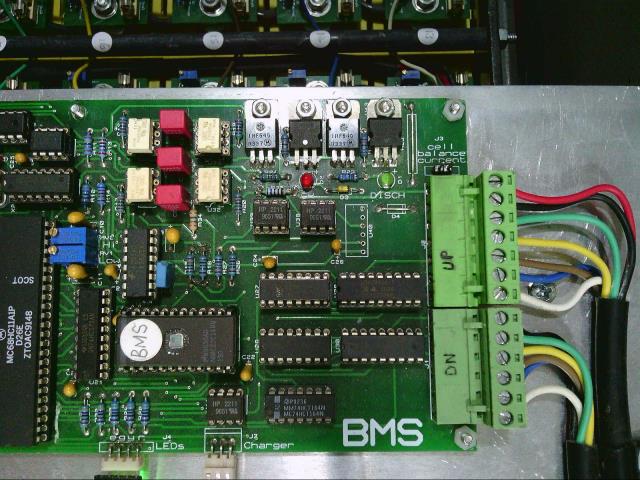 Top right hand corner (with the four TO220 packages) are the old now no longer used current source and current sink cell balancing system, with two opto isolators and an isolated power supply which has been removed from the PCB. I now do all the cell balancing on a PCB bolted to the top of each cell. Its an absolute tangle of wires, but I can see no obvious way of simplifying things. I used heavy 1mm squared red and black cable with spade connectors to link the common monitoring bus between PCBs. These originally had to carry the fairly high cell balancing current, but now they only do voltage monitoring. 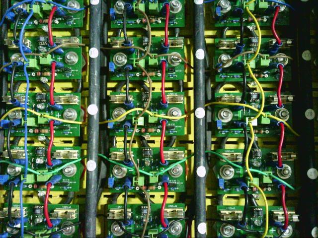 Cheers, ĀTony. |
||||
| Solar Mike Guru Joined: 08/02/2015 Location: New ZealandPosts: 1123 |
Going to modify the design for the BMS unit to add some extra functionality. 1: Want to use a small membrane 5 key pad to allow setting changes without re-programming. 2: Use an isolation amplifier to read the battery cell voltages, rather than the flying capacitor arrangement. 3: Use an I2c port extender for extra and slow speed IO. 4: Add remote current shunt sensing for both combined charge and common discharge currents (2 shunts) Plugin sense modules remain unaffected. Isolation Amp + filter. 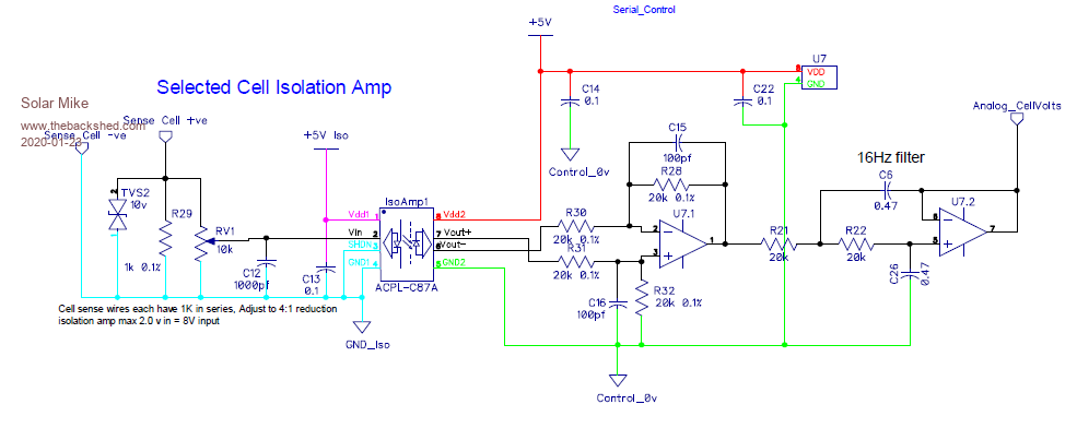 IO Extender: 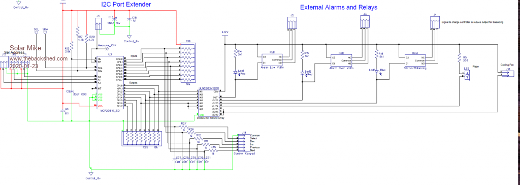 Schematic to date: BMS_DriverSchematic_2.03.pdf Cheers Mike |
||||
| Warpspeed Guru Joined: 09/08/2007 Location: AustraliaPosts: 4406 |
Somehow I missed your last post Mike. That ACPL-C87A is a great find and ideal for the purpose. It makes my flying capacitor system look pretty clunky. I may make another main BMS board fairly soon to tidy a few things up, and will give that ACPL chip a try. It will eliminate a lot of components. Cheers, ĀTony. |
||||
| Solar Mike Guru Joined: 08/02/2015 Location: New ZealandPosts: 1123 |
PCB almost done, latest schematic BMS_DriverSchematic_2.02.3.pdf Added Mux selection for 3 temperature sensors and provision to link to external current shunt module. Intended CPU Picaxe 20X2 as it has 2 wired interrupt pins, used for key pad and site network connection. CPU is on a a edge mounted card module, so easy to replace CPU with different type. Cheers Mike |
||||
| nickskethisniks Guru Joined: 17/10/2017 Location: BelgiumPosts: 411 |
Watching with great interest, just learned a few new components. :) I knew about the acpl-7800, the previous version? But never came to the idea to use it like you did. I hope to post my progress on the active balancer soon, maybe some inspiration for you... |
||||
| Warpspeed Guru Joined: 09/08/2007 Location: AustraliaPosts: 4406 |
Always interested in a different approach or any new ideas. Cheers, ĀTony. |
||||
| Solar Mike Guru Joined: 08/02/2015 Location: New ZealandPosts: 1123 |
Yes an active transformer coupled balancer would be a better more efficient solution than the design being used here. This design centralizes the electronics away from the batteries, rather than distributed at each battery cell, mainly for ease of testing and modification. The cell modules - circuit below, plug into the main pcb, one module per battery cell being monitored, each module connects across each cell to measure its voltage; balancing is accomplished by opto2 turning on logic level mosfet Q1 and placing a 3.5 amp load across the cell. As the voltage and load circuits are independent, if a cell is loaded its load is switched off during a voltage read, so we don't measure cable voltage drops. The load resistors are bolted to an alloy panel heat sink + fan. We are using 900 AH 6V lead carbon cells and 800 AH 3.2V Lifepo4 cells so the balance load has to be in proportion to make any headway, especially the Lifepo4 bank, as once the sharp voltage rise knee point is reached at near full charge, there is a limited time (an hour perhaps) to balance anything. 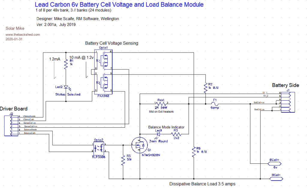 Cheers Mike |
||||
| Warpspeed Guru Joined: 09/08/2007 Location: AustraliaPosts: 4406 |
Mike, one idea (so far untried) that might be a simple solution to all the problems associated with noise and dc errors associated with a fully floating battery cell voltmeter. There can be horrendous 100Hz ripple coming from a hard working inverter, as well as high frequency hash from a solar controller, plus dc errors due to high voltage common mode leakage, noise picked up by the large mass of wiring, and small dc shifts introduced in the grounding. The most effective solution I have found so far, is of course heavy software averaging for the ac noise, and extreme care in avoiding small dc errors in the analog part of the system. We definitely need to average what we are measuring, ideally over at least 20mS and preferably over multiples of 20mS to average out the worst of the inverter ripple. We have plenty of time to do this, as the common voltmeter hops from cell to cell perhaps only once or twice per second. A completely different approach would be to use a fully floating voltage controlled oscillator. The frequency output could be very simply optically coupled into a ground referenced frequency counter. The advantage is that any noise or ripple will frequency modulate the oscillator, but we count up over say a couple of hundred milliseconds, any FM will be all averaged out over the measurement interval. Our frequency counter could count up to any number of bits, and we can ignore some of the least significant bits to further enhance the averaging. This would entirely eliminate any dc errors from common mode leakage or grounding errors, as its all completely digital after the oscillator. The oscillator can be scaled to have say zero frequency at 3.1v and full scale frequency at perhaps 3.6v, or whatever. Should not be that difficult to do, and its a very effective way I have had success with in the past of noise cancelling things such as low output analog transducers in a very noisy environment. Cheers, ĀTony. |
||||
| Solar Mike Guru Joined: 08/02/2015 Location: New ZealandPosts: 1123 |
Good suggestion Tony, when I first visited this design I was going to use a picaxe 08m2 as a precision pulse generator, where the pulse width was proportional to input voltage over a specified range; eg 2.6 to 3.6 volts = 260 - 360 mSec, the cpu could take many voltage measurements and average prior to sending the pulse, it would be floating and switched across the cells using same setup as currently. The output pulse coupled back by an opto isolator. With a centralized measuring system as I have here, I don't think it would make any difference over the current design. However perhaps if a pulse generator was placed across each battery cell and a synchronization scheme used on a common Rx opto bus, then a lot of the noise associated with long sense wires would be eliminated. A self calibration system could be used for all cell pulse generators, where a sync pulse from a master was equal to a preset width = N volts. Problem I have here is the site has 3 x 50v banks, I didn't want to build something that required a large handful of cpu's and associated electronics, thus the centralized design. What noise problems I get remains to be seen... Cheers Mike |
||||
| Warpspeed Guru Joined: 09/08/2007 Location: AustraliaPosts: 4406 |
Your design looks very good and should work fine. My own current system of flying capacitor isolator, successive approximation a/d converter and software averaging works fine too. I am just curious about trying out some rather different ideas and see how they go. This whole BMS story has turned out to be a very long road to hoe, and has proved to be much more challenging than building the inverter. There seem to be two very fundamental problems with measuring cell voltages. For anyone just starting out with this, the first requirement is to use the exact same voltmeter (of whatever type) to measure the voltage of each cell. Its not possible to get the cells balanced with a whole lot of different voltmeters that all read slightly different and drift with respect to each other over time. If the master voltmeter drifts very slowly, that is much less worrisome, each cell measurement will be wrong by the same amount and its the relative voltages we need to really be interested in for cell balancing. The other difficult thing is induced ripple and noise voltages on the cells. Its difficult to measure cells accurately down to to single millivolt levels if there are tens or hundreds of millivolts of noise and crap there. If the measured voltages are jumping around from reading to reading, any digital or graphical readout display will also be jumping around. That looks nasty, and is less than useful for discovering a successful cell balancing algorithm. Ā I have had dismal failure with numerous attempts at analog filtering out of noise, it just slows down the expected small step changes when the voltmeter switches abruptly from cell to cell. Software or digital averaging is much more effective. Yesterday, I bread boarded up an experimental voltage controlled oscillator using the cheap and cheerful AD654. It is remarkably stable with supply voltage and temperature changes. The only significant temperature effects were from the oscillator timing capacitor. That requires something fairly good. I had excellent results from both polystyrene capacitors, and a very high quality mil spec silvered mica capacitor that I already had. Quickest way to test is to use a digital readout capacitance meter and a can of spray freeze. I was seeing 5pF to 15pF changes in the better 1,800pF capacitors, between room temperature on a 32C day, and encrusted in ice. Anyhow, the circuit oscillates from zero (actually about 7Hz) at 3.1v dc input and about 32Khz at 3.5v dc input. That will go through a twelve stage ripple counter (divide by 16,384) and the last eight stages of that can be set up to count 00 at 3.1v input and FF at 3.5v input over about a half second count up time. That will be one of several different experimental master voltmeters I plan to test, that should be especially effective at digitally integrating out the noise over half a second or so. Edited 2020-02-02 07:19 by Warpspeed Cheers, ĀTony. |
||||
| Solar Mike Guru Joined: 08/02/2015 Location: New ZealandPosts: 1123 |
That AD654 looks like a good candidate for converting an isolated voltage to frequency scheme, using a binary counter or cpu to extract the noise free measurement. In the past I have used individual cell voltmeters that each had a 0.2% band gap reference as a master, the cpu in each cell voltmeter used that as an accurate measure to do its cell A_D conversions, the cpu converted the cell voltage into a timed duration output pulse via optocoupler for isolation; but I agree a single voltmeter would be easier to get going. Have completed the PCB layout for the BMS driver mother board. 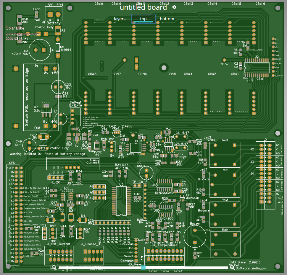 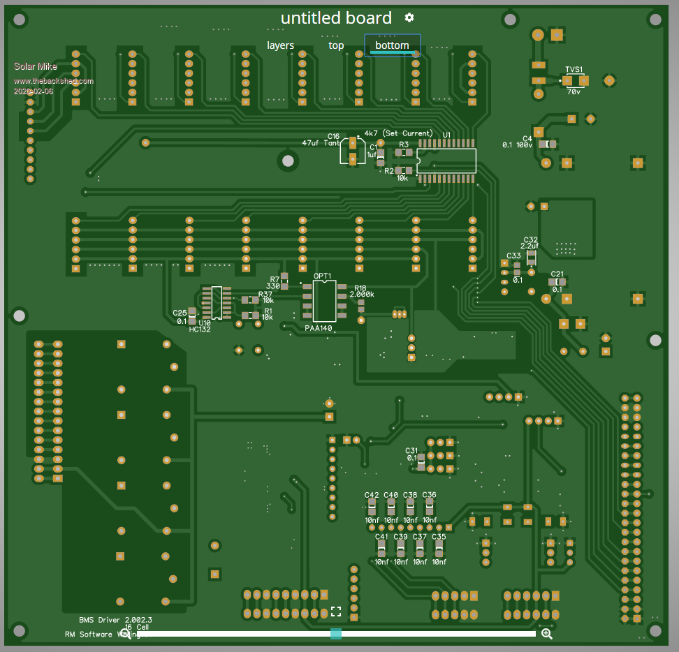 Will now do a cut and paste to add an optional extension pcb to allow 32 cells, as I will be converting my system here at home to 96 volts. Cheers Mike |
||||
| Solar Mike Guru Joined: 08/02/2015 Location: New ZealandPosts: 1123 |
16 cell extender board, they can be daisy chained to desired number of cells. Size is 145 x 90mm. 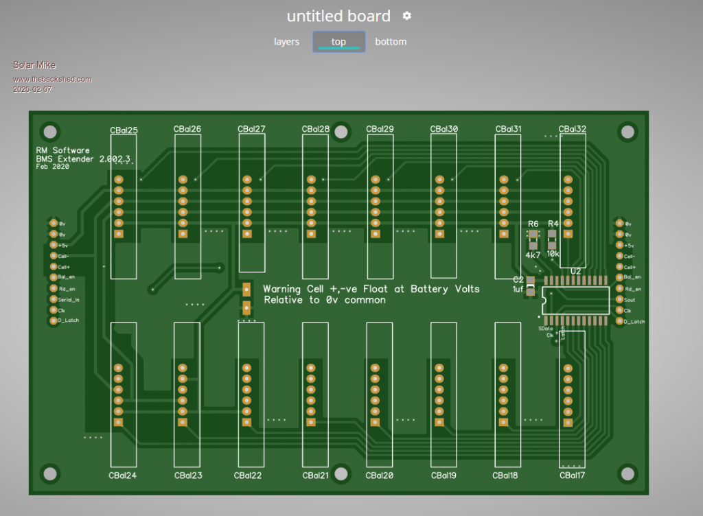 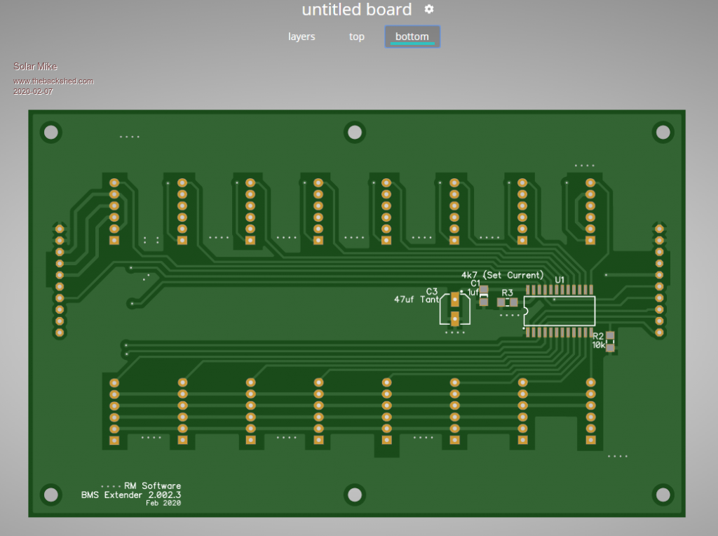 Cheers Mike |
||||
| Solar Mike Guru Joined: 08/02/2015 Location: New ZealandPosts: 1123 |
The remaining piece of this BMS puzzle to do is the current monitors; I am using 2 current shunts, one for charger inputs (PV and Generator), the other for Battery loads (inverters and DC direct lights etc.). Normally a single shunt is used with an output that has a zero point of say 2.5 volts, this allows a CPU to measure discharge loads < 2.5v and charge > 2.5v, however I wanted independent monitoring, a side bonus is the resolution is increased as all voltages begin at 0v and increase to around 4.0. The BMS will also act as a battery columb counter, so the state of battery capacity is always known, whenever the charge controller moves to "Float" the "On Float" relay will be used as an input to reset the columb count to 0. Schematic below will be basis for the remote current sense, perhaps at some point I will swap out the shunts and use Hall Effect current transducers. Circuit is basically an instrumentation amplifier + filter, specific Op Amps have been used for accuracy, a charge pump -0.3V rail has been used to allow true measurements to 0v. 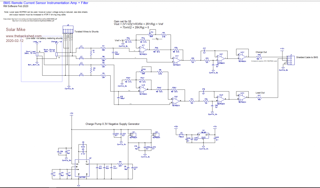 Schematic Remote Current Sense.pdf Edit: a good source for Single Rail Op Amps are these Texas Instruments 1 and Microchip Cheers Mike Edited 2020-02-12 13:25 by Solar Mike |
||||
| Solar Mike Guru Joined: 08/02/2015 Location: New ZealandPosts: 1123 |
Final PCB 72x94mm, the -ve rail charge pump will be useful in other projects that require true 0v sensing, so will place that part of the circuit on a small pcb with the same order. Top PCB, no components on the bottom. 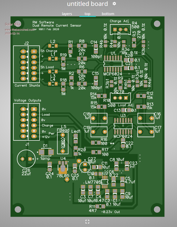 Cheers Mike |
||||
| Solar Mike Guru Joined: 08/02/2015 Location: New ZealandPosts: 1123 |
As the 5 volt to -ve 0.23 volt charge pump will be quite useful, have made a small pcb 19 x 32mm fitted with 4 pin rt angle pins; so it can be plugged in as a component. Will make things easier in future board designs. All gerbers have been sent off, JLCPBC have resumed production, with delays, quite understandable, see how long it takes to get here. 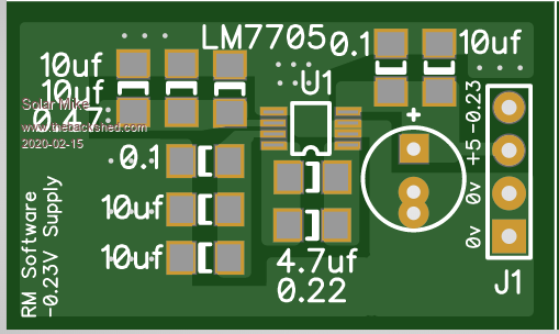 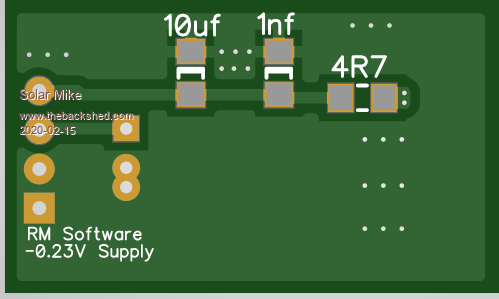 Cheers Mike |
||||
| Warpspeed Guru Joined: 09/08/2007 Location: AustraliaPosts: 4406 |
Your circuit boards always end up looking far nicer than any of mine. Very jealous.... Cheers, ĀTony. |
||||
| Solar Mike Guru Joined: 08/02/2015 Location: New ZealandPosts: 1123 |
Ah but looking good doesnt mean its going to work, especially ver 1.00. Secret is NOT to use the auto layout and router tools, on these less expensive designers like DipTrace, they never seem to give good results. Mike |
||||
