Notice. New forum software under development. It's going to miss a few functions and look a bit ugly for a while, but I'm working on it full time now as the old forum was too unstable. Couple days, all good. If you notice any issues, please contact me.
BenandAmber Guru Joined: 16/02/2019 Location: United StatesPosts: 961
Posted: 12:41am 05 Jun 2019
Copy link to clipboard
Print this post
What do you guys think about these capacitors 4 the High side secondary output filterbe warned i am good parrot but Dumber than a box of rocks
BenandAmber Guru Joined: 16/02/2019 Location: United StatesPosts: 961
Posted: 03:08am 08 Jun 2019
Copy link to clipboard
Print this post
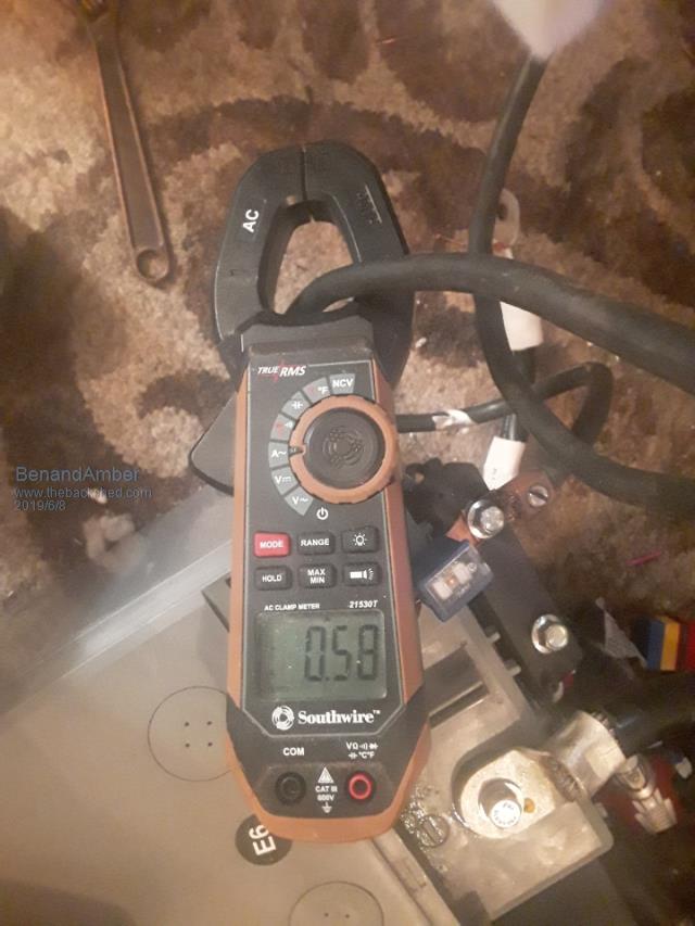
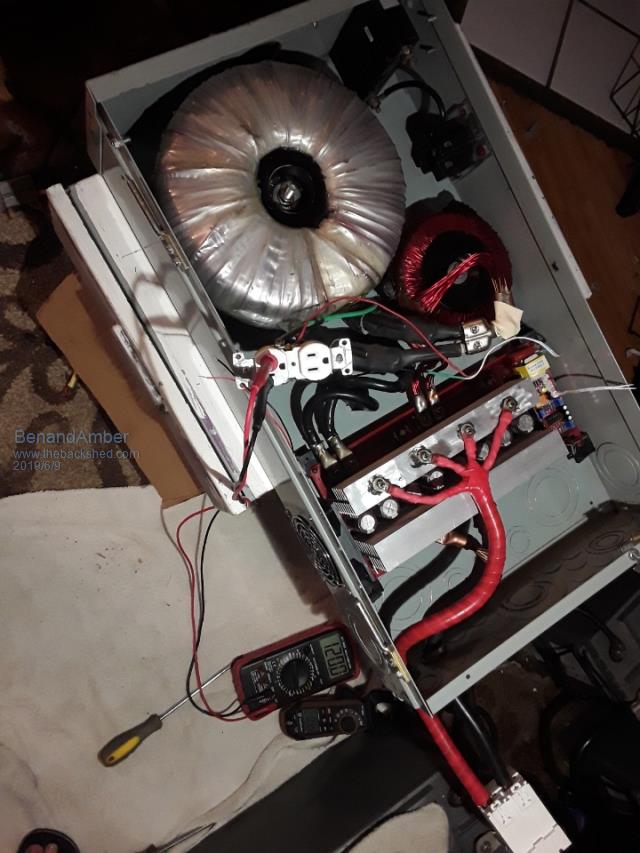
Still waiting on the 48 volt fans
The one fan that is in there as a 12-volt and I didn't hook it up for this test
It will be replaced with a 48 volt
Looks like I'm going to have to change out a couple resistors
The pot is turned all the way
I pretty much already knew this though
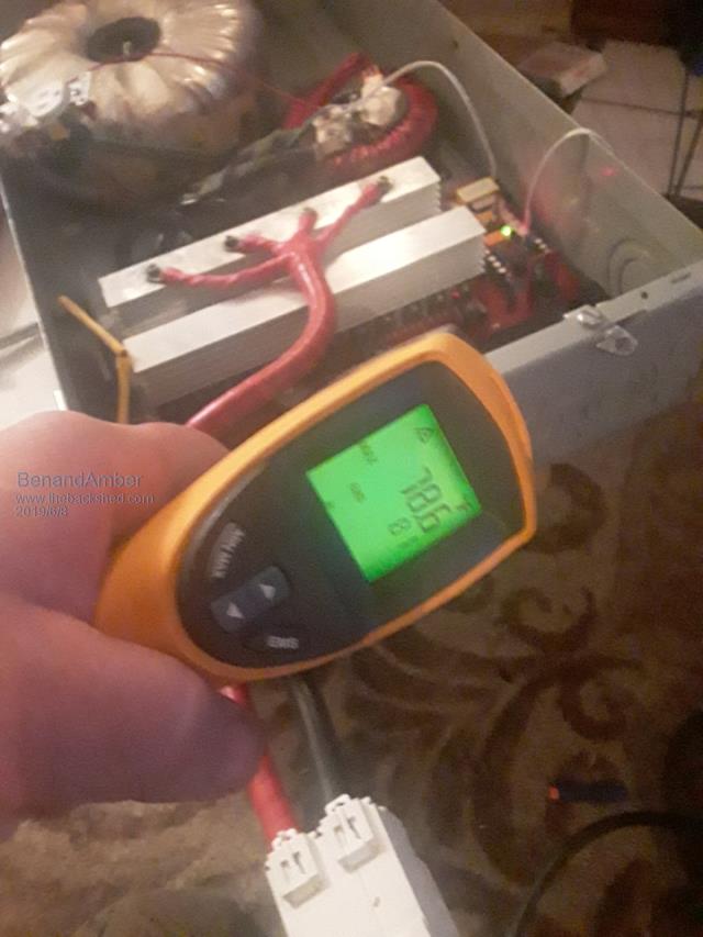
Everything seemed to run pretty cool
The highest temperature on the board was the front right totem pole drivers and they were like 80 degrees Fahrenheit
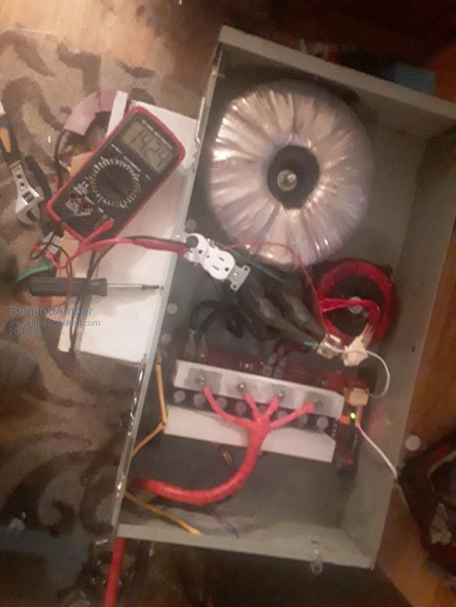
Would love to see the sine wave out of this machine
that big choke was originally made for a inverter
it had a lot more turns on it though I rewound it
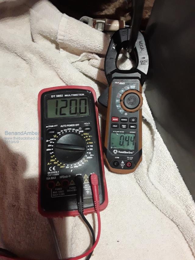
I'm hoping the idle current will go down a little bit when I replace a resistor and turn the voltage down to around 120
This project coming to an end just in time for the Nano happyhappyjoyjoy so excited
Thank all you guys for all the help and advice you gave me on this inverter
Edited by BenandAmber 2019-06-09be warned i am good parrot but Dumber than a box of rocks
BenandAmber Guru Joined: 16/02/2019 Location: United StatesPosts: 961
Posted: 03:22am 08 Jun 2019
Copy link to clipboard
Print this post
I really do not like that DC breaker it came from AliExpress
I just do not trust it
I cannot get the cables tight enough no matter how hard I strain
breaking the thing apart and still not tight enough for me
I have a hundred amp fuse in line with this also just in case
Not sure it has big enough capacitors on it either
It has 8 1500 uf 12000uf all together
That little 4 mosfet board that poida the great help me with has to 18000 uf capacitors that's 32000uf
So it has 20,000uf more
And I think there's something to that you guys would know a lot more about it
I think that's why the little one will start just about anything
Please comment if I'm wrong about this
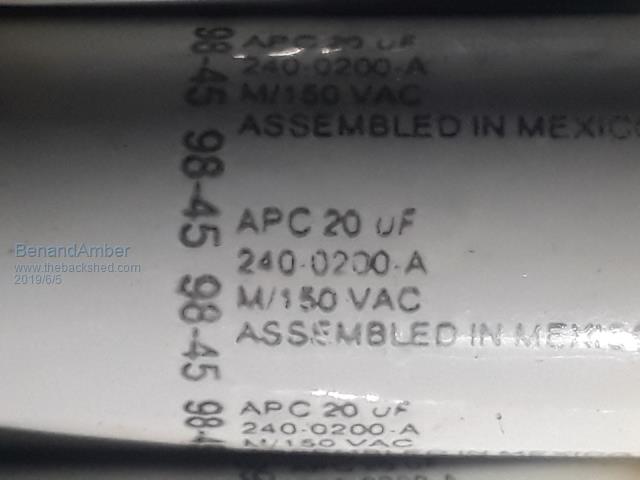
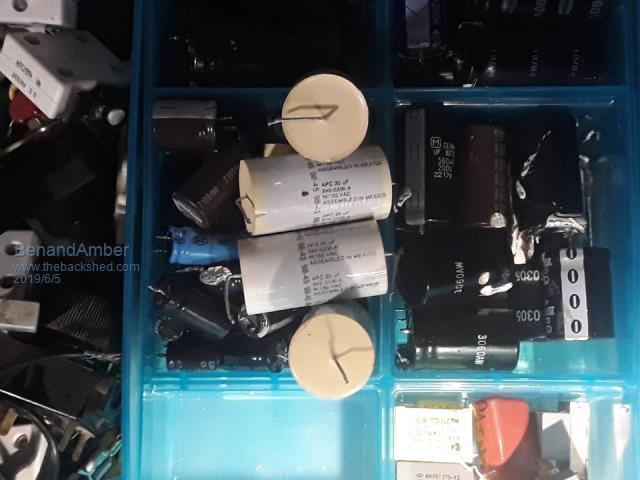
I would also like to know your guys's opinion on those film capacitors at the top of the page
I have four of them and they're out of two different APC UPS Edited by BenandAmber 2019-06-09be warned i am good parrot but Dumber than a box of rocks
nickskethisniks Guru Joined: 17/10/2017 Location: BelgiumPosts: 411
Posted: 07:40am 08 Jun 2019
Copy link to clipboard
Print this post
For your comparisson, (my)the 6kw OZinverter has 8pcs 100v 10000uF capacitors. It's not always the bigger the better, you need to have caps that are rated for high ripple current.
For those foil capacitors, looking good but you know that most of us use between 2 and 5uF, 20uF would probably be to high. I only use 2uF in mine, it depends a little bit what's best with your transformer. I got higher idle currents and misforming Sine WAVE with more then 5uf. Edited by nickskethisniks 2019-06-09
renewableMark Guru Joined: 09/12/2017 Location: AustraliaPosts: 1678
Posted: 12:07pm 08 Jun 2019
Copy link to clipboard
Print this post
Hello Ben, for the tuning capacitors on the secondary output I have used very different values for two different torroids that looked and were wired identically.
The first one needed 6uf to obtain the 75hz tuning, the second one needed a whopping 12uf to obtain the same tuning frequency.
Commonly if not tested, 4uf seems to be a standard number.
Warpspeed did the testing for me, I didn't have the ability to do it myself.
This is where a local mentor would be really handy, I have been very fortunate to have the local help from Warpspeed and Poida, and lots of phone help from Madness (probably drove him even more mad with all the stuff ups I did early on)Cheers Caveman Mark Off grid eastern Melb
BenandAmber Guru Joined: 16/02/2019 Location: United StatesPosts: 961
Posted: 03:38pm 08 Jun 2019
Copy link to clipboard
Print this post
I might put an ad in the paper
And see if I can find somebody around that is into Electronics
I had a friend about 15 or 20 years ago that could do about anything with electronics
He would fix our amps for us back in the head banging mosh pit days
I don't know if he's even still alive he was a very heavy guy
An absolutely awesome person though
I'm getting ready to put in an order at digikey
I was hoping to get the parts list for the warp speed control board
so I can order it all at the same time as the Nanobe warned i am good parrot but Dumber than a box of rocks
BenandAmber Guru Joined: 16/02/2019 Location: United StatesPosts: 961
Posted: 07:30pm 08 Jun 2019
Copy link to clipboard
Print this post
Thanks for the info Nick and the one and only mark
The APC capacitor say 20 if but they measure around 18
I was hoping not to have to buy any more capacitors
I have a 5 UF on it right now but I'm running out of the smaller UF capacitorsEdited by BenandAmber 2019-06-10be warned i am good parrot but Dumber than a box of rocks
BenandAmber Guru Joined: 16/02/2019 Location: United StatesPosts: 961
Posted: 07:39pm 08 Jun 2019
Copy link to clipboard
Print this post
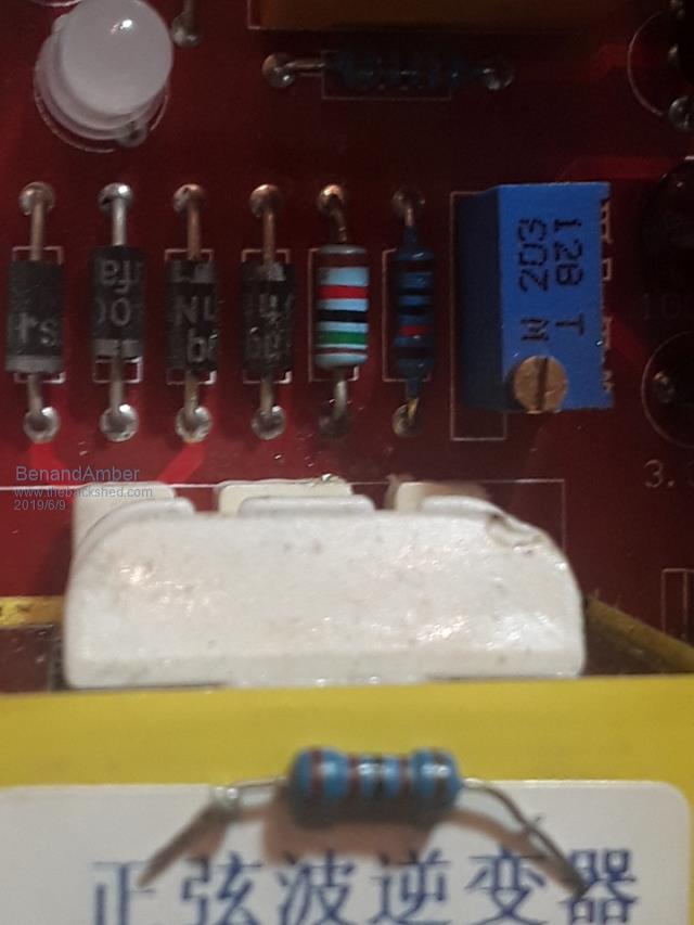
This picture shows the 21 k resistor I took out
it is on top of the Transformer
It also shows in the circuit the 15K resistor I replaced it with
This gave me a lot of leadway both up and down on the voltage feedback
I put this up in case anyone else decides to get this board
and needs to change it to 110 volts instead of the 220 volts be warned i am good parrot but Dumber than a box of rocks
BenandAmber Guru Joined: 16/02/2019 Location: United StatesPosts: 961
Posted: 03:44am 09 Jun 2019
Copy link to clipboard
Print this post
Now that's a little bit more like it
And completely silent
if you stick your ear literally against the big Transformer
you can barely hear a little hum
The choke makes no noise at all
Took it all apart today and gave it a last good cleaning and installed the 48 volt fans
Still haven't wired them up yet
I also put a breaker in it and a Giant RV plug
I will run a female end of a RV plug From my RV breaker box and plug it into the side of this inverter
If I ever need to plug into a RV hookup I will unplug it and plug it into my 50 ft long RV plug
I will be putting a female plug-in on one side of it
With doing it this way there will never be an accidental plug-in while the inverters running
A mosfet on the right side front being the side with feedback Transformer is 2 to 5 degrees hotter than all the rest
I didn't run it hard tonight just mainly small loads
During this time all mosfets stayed at 79 degrees except for that one in the front and it ranged from 80 to 84 degrees
Is this something to worry about should I change it
I plan on running that hard tomorrow or the next day
don't want to run it hard till I hear back from you guys Edited by BenandAmber 2019-06-10be warned i am good parrot but Dumber than a box of rocks
poida Guru Joined: 02/02/2017 Location: AustraliaPosts: 1389
Posted: 04:19am 09 Jun 2019
Copy link to clipboard
Print this post
It looks great to me. I would try larger loads in increments. eg a 500W, all OK? then a 1000W all OK? 1500W? etc
I would not just go nuts and "see if it breaks when I do this to it.." like on the Little China Board.
I find I can hear it when things are not happy.
Did you protect the IR2110 outputs with TVS diodes? Maybe in the case of this board with the totem pole drive, it's completely unnecessary.
I would not fit them if it was me. But that decision would be made after I examine the gate drive outputs with a CRO to prove they never go into potentially damaging voltages (less than -0.3V or more than 12.3V) wronger than a phone book full of wrong phone numbers
BenandAmber Guru Joined: 16/02/2019 Location: United StatesPosts: 961
Posted: 05:02am 09 Jun 2019
Copy link to clipboard
Print this post
No zener diodes on this one several post back you told me it wasn't necessary
I appreciate you so much poida the great
you brought so much enjoyment into my life
And helped me reach my dream of being offgrid be warned i am good parrot but Dumber than a box of rocks
azhaque Senior Member Joined: 21/02/2017 Location: PakistanPosts: 117
Posted: 08:10am 09 Jun 2019
Copy link to clipboard
Print this post
Hi Ben,
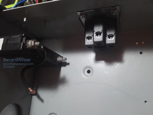
Every time see the photo of the connection to the heatsink, it gives me the creeps.
Looks like a red alien hand with four fingers coming out from underneath the board and trying to grab the heat sink.
You sure you haven't got a pet alien in your w/shop
azhaque
BenandAmber Guru Joined: 16/02/2019 Location: United StatesPosts: 961
Posted: 08:21am 09 Jun 2019
Copy link to clipboard
Print this post
That's funny Azhaquebe warned i am good parrot but Dumber than a box of rocks
Revlac Guru Joined: 31/12/2016 Location: AustraliaPosts: 961
Posted: 11:38am 09 Jun 2019
Copy link to clipboard
Print this post
Inverter Looks good Ben would like to see what the sine wave looks like. I don't see an EMI filter there on the output, are you going to put one in? Also the PM is not getting through.Cheers Aaron Off The Grid
BenandAmber Guru Joined: 16/02/2019 Location: United StatesPosts: 961
Posted: 02:36pm 09 Jun 2019
Copy link to clipboard
Print this post
I would also like to see the sine wave
I have a 5 UF capacitor on the bottom of that receptacle I have wired up temporarily
That choke was originally made for a large inverter
I unwrapped two of them and use the wire from both of them on the one that's in this inverter
It makes absolutely no sound at all
the big Transformer barely hums if you put your ear down to it
I'm going to retest that homemade Transformer that me and Amber built from scratch
It don't look good for the home team on that one
Unless the low side primary not being on their effects it
My inbox was full I'm sorry and hope u will forgive me and keep PM messaging me
I'm going to have to keep a better eye on that
I seen an advertisement for a scope that plugs into a laptop it's like 80 bucks
I can probably get an old broken laptop pretty much free
Me and my wife used to run a business fixing computers and an internet cafe
That's before computers became throw away items
I won't have any problem fixing a computer it's the software that is complicated
If anyone's had any experience with the scope I'm speaking of
I would really like to hear about itEdited by BenandAmber 2019-06-11be warned i am good parrot but Dumber than a box of rocks
BenandAmber Guru Joined: 16/02/2019 Location: United StatesPosts: 961
Posted: 04:26pm 09 Jun 2019
Copy link to clipboard
Print this post
My box is full again please forgive me I emptied itbe warned i am good parrot but Dumber than a box of rocks
BenandAmber Guru Joined: 16/02/2019 Location: United StatesPosts: 961
Posted: 02:41am 11 Jun 2019
Copy link to clipboard
Print this post
Thanks everybody for the compliments
you can basically think yourselves without your guys's help
I wouldn't have been able to do it
Been testing a little bit more today
hooked a 15000 BTU window air conditioner
and a 1500 watt heater and other things I could find a plug into it
All at the same time
Everything seems to run great
I don't have anything bigger than hook into it
I guess I'll just keep on adding stuff to it
the big Transformer does make it louder humming sound with the air conditioner running
it's still very quiet
No noise at all out of the choke completely silent
No fans hooked up mosfets up to about 90 degrees and settled in there
The 20 amp receptacle got a little bit hot the touchEdited by BenandAmber 2019-06-12be warned i am good parrot but Dumber than a box of rocks
BenandAmber Guru Joined: 16/02/2019 Location: United StatesPosts: 961
Posted: 04:10am 12 Jun 2019
Copy link to clipboard
Print this post
Only one complaint so far
I would like to have a lot bigger caps but they just won't fit in between the heat sinks
If I had it to do over again I would remove the ones that came with the board
Then Mount big ones on the bottom sidebe warned i am good parrot but Dumber than a box of rocks
johnmc Senior Member Joined: 21/01/2011 Location: AustraliaPosts: 282
Posted: 05:49am 12 Jun 2019
Copy link to clipboard
Print this post
Well done Benanamber Another inverter builder, be careful it can become addictive. Cheers johnjohnmc
Tinker Guru Joined: 07/11/2007 Location: AustraliaPosts: 1904
Posted: 09:27am 12 Jun 2019
Copy link to clipboard
Print this post
Always thought that placing the caps between the heat sinks is about the worst place for them. But it makes for a compact board, the only pro I can think of.
On my PCB's they always were on the bottom side.
However, remember that a bigger capacity makes a bigger 'bang' if something goes wrong. Also, the PCB tracks need to be up to the task of handling the bigger charge/discharge currents. There is a lot more than replacing a component here and there, to these commercial inverters, if one tries to improve them.
Keep up reading posts Ben, even if it appears you are the fastest guru in the west on this forum . Klaus