Notice. New forum software under development. It's going to miss a few functions and look a bit ugly for a while, but I'm working on it full time now as the old forum was too unstable. Couple days, all good. If you notice any issues, please contact me.
mackoffgrid Guru Joined: 13/03/2017 Location: AustraliaPosts: 460
Posted: 02:57am 07 Aug 2019
Copy link to clipboard
Print this post
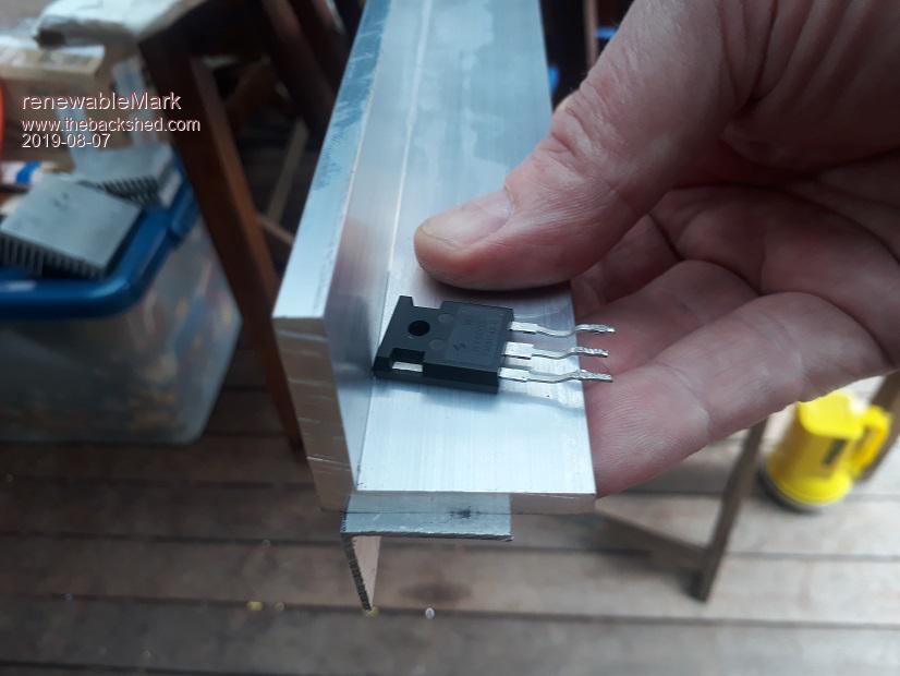
They're 1000 mil apart.
I've never worked out thermal equations. I start with a reasonable guess and adjust. If its too hot to touch and hold on to then it's too hot
These Mosfets should never see full power. I think his inverter is aiming for 8kWatts rms. So the large inverter section share is 5336 Watts rms. He has 6 mosfets per quadrant, so 890 Watts per Mosfet. At 50v that's 18 Amps rms per Mosfet (the lower Mosfets will be higher ). Rds is 2.9mR but even at 10mR Rds (this is switching at only 100hz) this is in the order of 3 Watts.
I wonder if a fan will ever come on or have I stuffed up the numbers?
Cheers Andrew
Warpspeed Guru Joined: 09/08/2007 Location: AustraliaPosts: 4406
Posted: 03:03am 07 Aug 2019
Copy link to clipboard
Print this post
I agree, but its always better to have one more trick than you really need.
Haha, rule of thumb. If you can hold your thumb on it without actually screaming, its not getting too hot.Cheers, ĀTony.
renewableMark Guru Joined: 09/12/2017 Location: AustraliaPosts: 1678
Posted: 05:25am 07 Aug 2019
Copy link to clipboard
Print this post
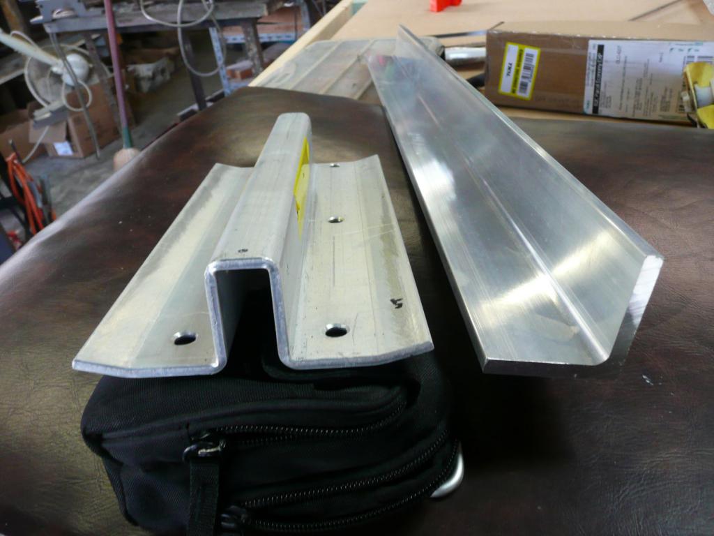
That length of Al was only $20, maybe get another and put it back to back like this.
The most it will ever cop is 4kw for extended times on really hot days when both air cons are going.
The house normally ticks along with a few hundred watts. Fridge goes on and pulls another 300w. Central heating fan pulls 400w. Dinner time the electric oven pulls 2000w
Av between 6-10kwhr a day, so it's not going to get a real hiding.
.Cheers Caveman Mark Off grid eastern Melb
renewableMark Guru Joined: 09/12/2017 Location: AustraliaPosts: 1678
Posted: 05:37am 07 Aug 2019
Copy link to clipboard
Print this post
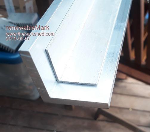
Or sit them inside each other, if doing it this way I'd buy a 50x50 to sit at the bottom. This layout will be easier.
The inside and outside corners are nice and sharp, so they will fit together fine.
. Edited 2019-08-07 15:38 by renewableMarkCheers Caveman Mark Off grid eastern Melb
Warpspeed Guru Joined: 09/08/2007 Location: AustraliaPosts: 4406
Posted: 05:40am 07 Aug 2019
Copy link to clipboard
Print this post
That sounds like an excellent plan.
What I was doing was a 2Kw switching power supply with only one mosfet. It worked but only just. My second attempt was with the copper blocks AND two mosfets in parallel which was probably gross overkill.
I only mentioned the copper idea as a heads up possibility.
Don't stress yourself out, Mack is quite right, the fans will probably never come on in normal use. Mine never have.Cheers, ĀTony.
mackoffgrid Guru Joined: 13/03/2017 Location: AustraliaPosts: 460
Posted: 06:23am 07 Aug 2019
Copy link to clipboard
Print this post
You want to see my Latronics inverter. It's a 24v 3kW inverter that works really well. Until the fan died but that's not their fault. (I don't think) I better fix that tomorrow
The aluminium heatsink is minuscule compared to ours. They rely on fans a lot more. It does cut out on temp. On those very hot days I try not to load it too much or it shuts itself down.
I'll post a photo of it tomorrow.
Cheers Andrew
renewableMark Guru Joined: 09/12/2017 Location: AustraliaPosts: 1678
Posted: 06:30am 07 Aug 2019
Copy link to clipboard
Print this post
Reckon I'll get another length of 50x50x6mm to sit under the other one.
Bolt those two together, then they can bolt onto the finned heatsink.
That bigger surface should probably have a heat transfer helper.
What works better silicone sheet or the paste?
.Cheers Caveman Mark Off grid eastern Melb
mackoffgrid Guru Joined: 13/03/2017 Location: AustraliaPosts: 460
Posted: 06:32am 07 Aug 2019
Copy link to clipboard
Print this post
I would say paste. Silicon sheet is generally used only when you want to insulate the transistor and heatsink.
Warpspeed Guru Joined: 09/08/2007 Location: AustraliaPosts: 4406
Posted: 06:36am 07 Aug 2019
Copy link to clipboard
Print this post
Use the white goo Mark.
Just a smear, then bolt the sucker up. When all the excess has squeezed out re torque the screws and then forget about it.Cheers, ĀTony.
renewableMark Guru Joined: 09/12/2017 Location: AustraliaPosts: 1678
Posted: 07:01am 08 Aug 2019
Copy link to clipboard
Print this post
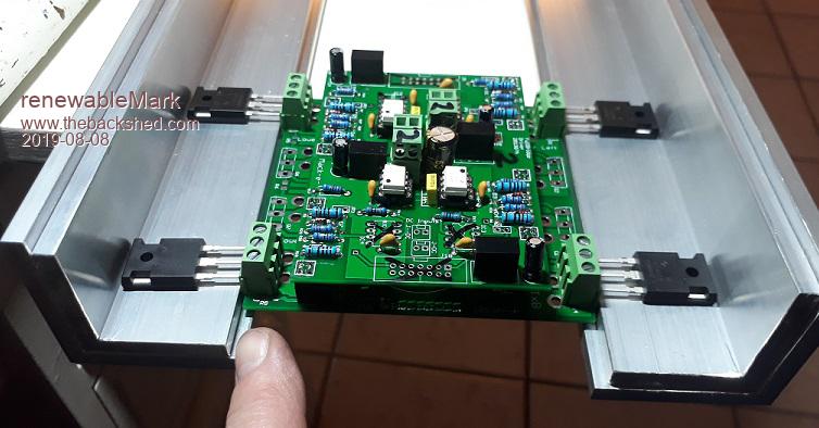
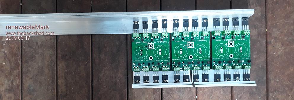
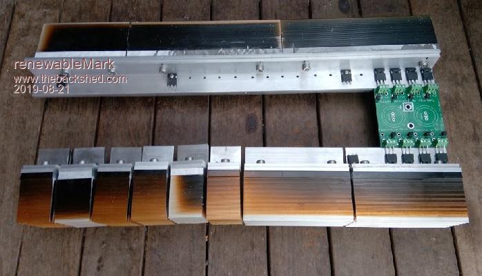
This is what I ended up with.
The 50mm sticks out just enough to be a threat to the terminals under the plug, so that will get put on the table saw and trim it back (where my finger is pointing)
Cheers Caveman Mark Off grid eastern Melb
renewableMark Guru Joined: 09/12/2017 Location: AustraliaPosts: 1678
Posted: 10:53am 09 Aug 2019
Copy link to clipboard
Print this post
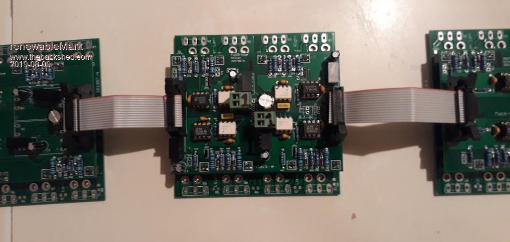
Hey Andrew, just checking that the orientation for the cables is correct.
Cheers Caveman Mark Off grid eastern Melb
mackoffgrid Guru Joined: 13/03/2017 Location: AustraliaPosts: 460
Posted: 01:06pm 09 Aug 2019
Copy link to clipboard
Print this post
Looks Good.
The notches of the PCB headers should all be the same way as well.
I see you've used IDC headers with ears. I always draw PCBs just using the "Boxed" headers because they take up less PCB space.
BTW, if you ever wish to probe the test points with your scope, I bought some cheap BNC leads on ebay, cut off the alligator clips and soldered on one of those 2 pin header sockets. Then if you haven't soldered in the test points, I just plug in a 2 way header pins into the lead and they seem to sit reliably into the PCB holes. The round pad of the test pins are always local gnd.
Cheers Andrew
renewableMark Guru Joined: 09/12/2017 Location: AustraliaPosts: 1678
Posted: 06:48am 17 Aug 2019
Copy link to clipboard
Print this post
Thanks Andrew, mine got the sockets with lockdowns as that's all that alltronics had, Jaycar didn't have anything in 14 pin and I didn't want to wait for O/S delivery.
Making slow progress cutting and tapping the bars.
Ran out of screws, off to jaycar tomorrow .....again.
.Cheers Caveman Mark Off grid eastern Melb
mackoffgrid Guru Joined: 13/03/2017 Location: AustraliaPosts: 460
Posted: 11:12am 19 Aug 2019
Copy link to clipboard
Print this post
Hi Mark
That last photo looks very nice.
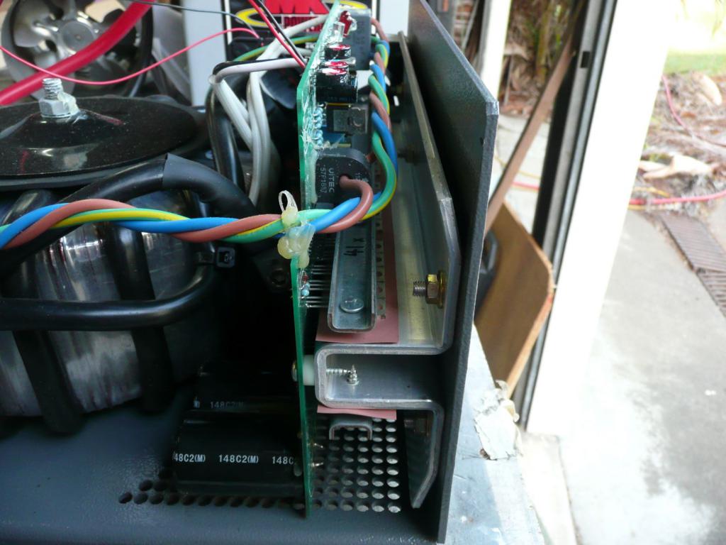
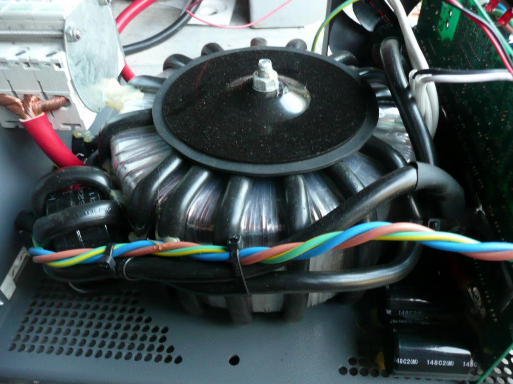
I said I would show some photos of the Latronics Heatsink.
Heatsinking of a 3kW 24v Latronics.
The unit works quite well and when the fan failed would easily trip on over-heat (electric kettle), but it did so gracefully. The Fan is now replaced. As a side note, they were buggers as they pop riveted the fan in, and necessitated that I bring the inverter back to Town - A fan should be field serviceable. Even then the little aluminium brackets were difficult to re-use. Luckily a simple little 3d printed part was printed and worked real well - so much I'm going to use it to hold the fan in the WarpVerter.
I took this photo of the Latronics heatsink. The Al angle next to it is 50x50x6mm.
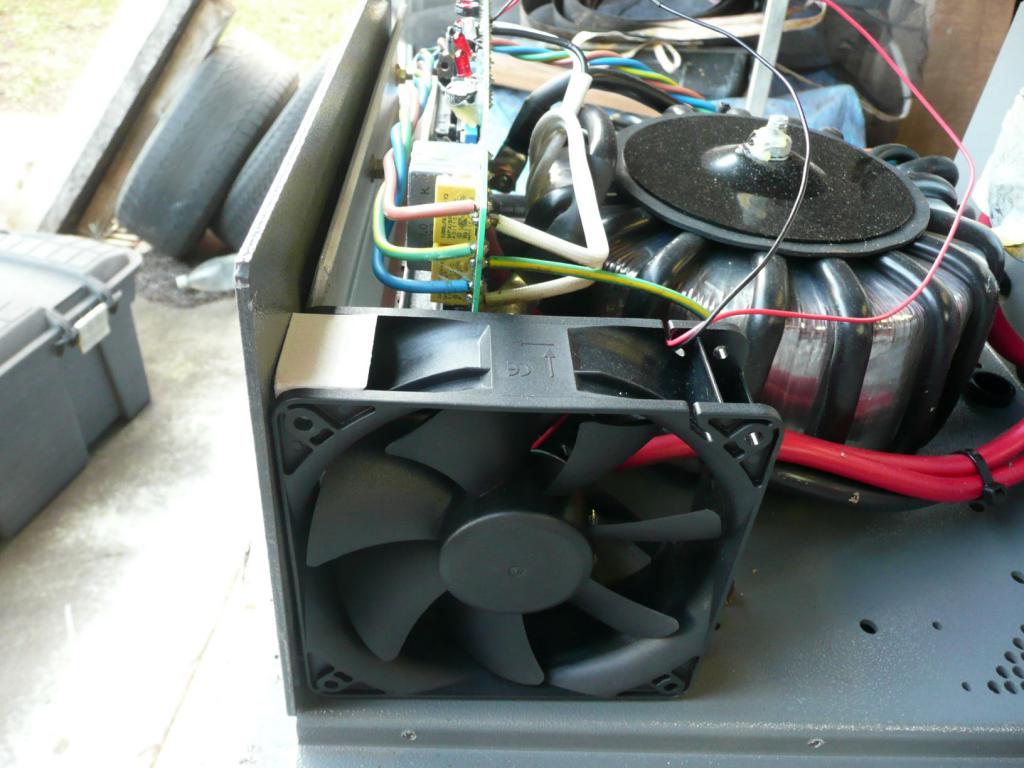
And inside the Box.
Very reliant on the Fan. See the White 3d printed part holding the Fan. A slot in the part fits over some webbing within the Fan.
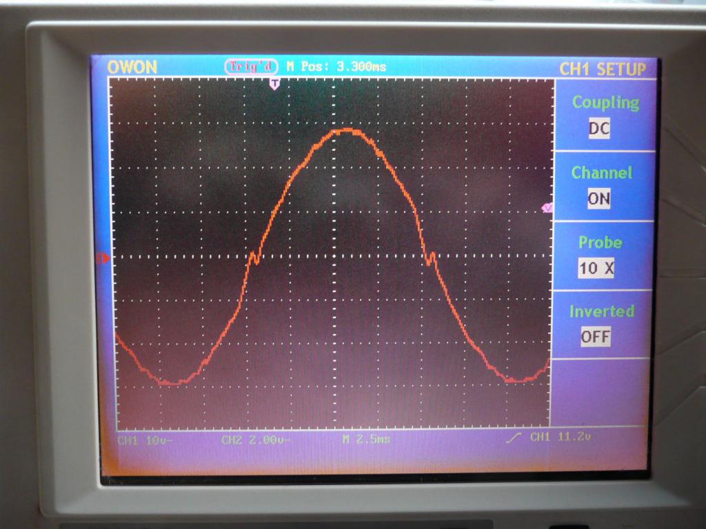
Another glamour shot
And finally an action shot. About 120W load.
Cheers Andrew
renewableMark Guru Joined: 09/12/2017 Location: AustraliaPosts: 1678
Posted: 06:03am 21 Aug 2019
Copy link to clipboard
Print this post
Yeah those Latronics aren't made to be worked on.
I have a couple of the GTI low input voltage units that will get incorporated into my system at some point.
I finally got the heatsinks all done. The way I did these made it VERY fiddly lining everything up compare to an Oz/Madinverter.
Tapping the thread between two layers/thicknesses of angle was fiddly. I ended up just tapping the bottom bit of angle and drilling out the upper one slightly bigger. So the fet sits on top, goes through the top heatsink loosely, then threads into the bottom heatsink.
Glad that's out of the way.
. Edited 2019-08-21 16:10 by renewableMarkCheers Caveman Mark Off grid eastern Melb
Warpspeed Guru Joined: 09/08/2007 Location: AustraliaPosts: 4406
Posted: 06:14am 21 Aug 2019
Copy link to clipboard
Print this post
Its much better to put all the sweat and toil into initially building something really nice that is an absolute joy to work on.
And one of Murphy's laws states that: Ā "Anything that is accessible and able to be very easily replaced will never fail".
That is actually better.
Heaving down on the screws will press the two pieces of angle together for best thermal contact right under the mosfet, where its most important.
If both pieces are tapped, there may be an absolute minimal gap remaining, which will act as a heat barrier, and that defeats the whole purpose.
De bur all the holes, as I am sure you already have, so the two angles are up close and intimate with each other, with nothing anywhere that might spread them apart. Edited 2019-08-21 16:57 by WarpspeedCheers, ĀTony.
renewableMark Guru Joined: 09/12/2017 Location: AustraliaPosts: 1678
Posted: 07:31am 21 Aug 2019
Copy link to clipboard
Print this post
Yeah, that's what I found. Even really tight clamping didn't help when tapping the threads of the two bits of angle, they always seemed to have a tiny gap which would never get snugged up.
So the solution was to drill out the upper one, that brings them nice and closely aligned together now.
The connection between those two bits of Aluminium angle will remain clean and I'll only put the heatsink compound between the angle and finned heatsinks.Cheers Caveman Mark Off grid eastern Melb
Warpspeed Guru Joined: 09/08/2007 Location: AustraliaPosts: 4406
Posted: 07:59am 21 Aug 2019
Copy link to clipboard
Print this post
Great stuff Mark
If you are down this way, and you want to do the 75Hs tuning trick with your "other" inverter, just let me know when, so I can be sure to be here.Cheers, ĀTony.
renewableMark Guru Joined: 09/12/2017 Location: AustraliaPosts: 1678
Posted: 06:08am 24 Aug 2019
Copy link to clipboard
Print this post
Thanks Tony, I'll sing out and see if the time suits you.
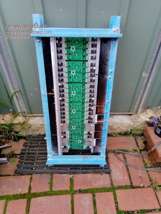
Got a bit more done today.
Will mount the slides to the locker and the frame next.
Then number it all and pull it all apart to remove all the burrs and filings etc.
It feels very solid the way it is now.
On the reverse it will have some more bars going across to support the caps, might do the perspex sheet with the cap profiles cut out like Tony suggested.
.Cheers Caveman Mark Off grid eastern Melb
Warpspeed Guru Joined: 09/08/2007 Location: AustraliaPosts: 4406
Posted: 07:34am 24 Aug 2019
Copy link to clipboard
Print this post
That blue fibreglass looks like very nice stuff to work with. I can well believe its all ended up being very rigid.
A couple of heavy duty ball bearing slides, and you are set.Cheers, ĀTony.