
|
|
Forum Index : Electronics : Stock Std Warpinverter
| Author | Message | ||||
| brucedownunder2 Guru Joined: 14/09/2005 Location: AustraliaPosts: 1548 |
Hi Mark. Yep,on mine years ago , I wound 25mm insulated wire building wire and had the same problem -so, I just kept going and had a few turns overlapping . In the end result ,it made no difference ,all worked perfect.-looks a bit "ordinary" but so do I ,so no problems I heard that John (Oztules) ,an original on this board is not too well. I send Ilda and My thoughts to him ,and hope he has a speedy recovery-He is one of our "legends" with lots of projects that have given "backshed' er's lots of encouragement. Bruce Bushboy |
||||
renewableMark Guru Joined: 09/12/2017 Location: AustraliaPosts: 1678 |
I remember seeing that pic, I'm not concerned how this looks. The problem is it's recyled enameled wire, your torroid was using rubber insulated wire from memory. The enamel on this wire is basically just a paint. If there is a scratch in the wire and the next turn happens to rub up on it and it also has a scratch that miraculously lines up with the other, those two wires will have a volt or so between them. BUT, if the start of the secondary has an overlap from the end of the winding that has gone all the way around the core and gone back over the start, then there will be a huge difference in voltages between the two wires. Hence the polyurethane coat, then a mylar wrap before proceeding with the final turns. No chance of start and tail end of the winding coming into contact. When you handle this recycled wire a lot, you will come across some scratches, they are usually quite easy/pronounced to feel and seem like if they rubbed on a wire next to them, they could easily wear off the enamel on the adjacent wire. So the theory is that if they get gooped up with polyurethane they, 1. firstly get a coating of insulation, and 2. secondly get the rubber shock absorbing properties to reduce the hum/vibration of the torroid. Whenever I do see a scratch in the wire it gets a few turns of tape on it and gets wound on as normal. Every time I hear a transformer hum it makes me cringe, those wires are basically buzzing and vibrating next to one another, and that can't be good for wires with a thin enamel coat protecting them from the wires next to them. Cheers Caveman Mark Off grid eastern Melb |
||||
| BenandAmber Guru Joined: 16/02/2019 Location: United StatesPosts: 961 |
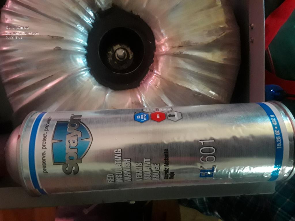 The wire we used on the last Transformer was pretty scratched up We purchased a couple cans of this stuff shown in picture We painted the complete wire after stretching it up across the yard be warned i am good parrot but Dumber than a box of rocks |
||||
| Warpspeed Guru Joined: 09/08/2007 Location: AustraliaPosts: 4406 |
All very good advice guys. Cheers, ĀTony. |
||||
| renewableMark Guru Joined: 09/12/2017 Location: AustraliaPosts: 1678 |
The closest thing I found available here in Aus is this one from repco That's probably a better idea for the fellas in hotter climates. Here in Melbourne it doesn't get too hot normally. Summer we can get stretches of 35c and occasionally 40+c. That leads me to another project I thought of, using peltiers to provide cool air into the case. When it's hot it normally means bright sunny skies, so we have an abundant power supply, therefore using inefficient peltiers is no concern. A cheap thing that could be used in hot spells could be useful. Cheers Caveman Mark Off grid eastern Melb |
||||
mackoffgrid Guru Joined: 13/03/2017 Location: AustraliaPosts: 460 |
I've not ruled out using a split Aircon to cool an equipment room down. Those 45 degree days are horrific. But good forced air can achieve a lot. Cheers Andrew |
||||
| brucedownunder2 Guru Joined: 14/09/2005 Location: AustraliaPosts: 1548 |
Yes Mark , I remember now , you are talking about the secondary winding, mine was the heavy primary that I had to mess with . I have not tortured myself with winding a secondary yet. Mind you ,that 25mm insulated building wire was enough to settle me down -I promised myself ,stuff the kids,I'll spend some of their money on a factory built inverter !!. That hasn't happened yet,plenty of other projects being finished. 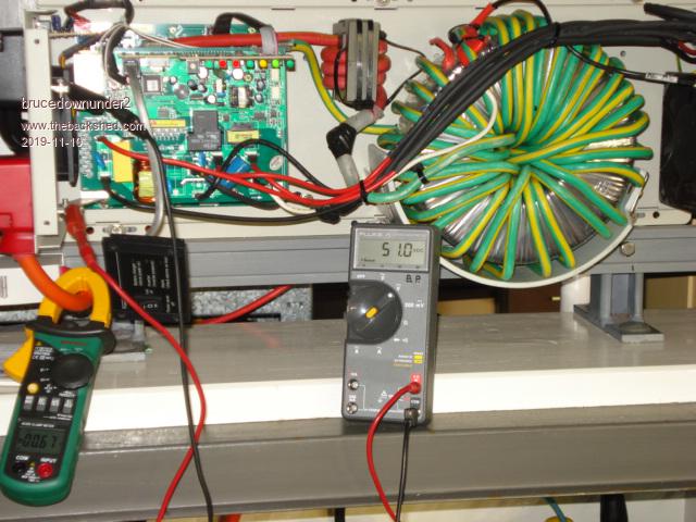 Bruce Bushboy |
||||
| renewableMark Guru Joined: 09/12/2017 Location: AustraliaPosts: 1678 |
Andrew, I was thinking of something like this Those blue jackets on the side are meant to take away the heat from the peltiers, centre area blows the cool air from the cooled heatsinks. So we are using a fan to force air anyway, sunny day has gobs of spare energy on a decent system, so the added power from peltiers shouldn't be a problem. Wonder if you could use a thermosyphon on those water jackets instead of a pump? Of course you can always make up one yourself and just use heatsinks with fans instead on the water jacket to dispel the heat from the hot side of the peltiers. 4 in series from the battery voltage would make it simple. Edited 2019-11-10 08:12 by renewableMark Cheers Caveman Mark Off grid eastern Melb |
||||
| Warpspeed Guru Joined: 09/08/2007 Location: AustraliaPosts: 4406 |
I did a bit of experimental work with peltiers a few years back, and they are certainly interesting devices, but pretty useless for any real practical application. There are reasons why nobody is mass producing pelter domestic refrigerators, freezers, or air conditioners. Its certainly constantly been thought of, but the damned things are just not efficient enough or cheap enough to be practical. Looking at the whole inverter cooling problem, a reasonable overall expected efficiency for a large inverter near full power might be in the region of 93%, so if we are making 5Kw we may need to get rid of about 350 watts of heat, maybe 450 watts tops. Its not a whole lot of power. ĀThe problem though, is the parts that get hot (heatsinks and transformers) are very heavy, but not that physically large with limited surface area, and the temperature rise can slowly build up and become excessive with steady and prolonged usage. The only real solution to that, is massive cooling airflow. Sheer volume of air directed directly between heat sink fins and around transformers, with high air velocity. Forget 12v computer fans, they are wimpy little things just for show. What you need is the 230 volt air blower out of something that will comfortably heat a decent sized room. Ā If it has to be 12v, try a car heater fan. Ā But as the inverter generates 230v anyway, it should be able to spare an extra 15 watts or so to drive a decent 230v air blower. A leaf blower would be overkill, and noisy. But think in terms of LOTS of airflow directed right at what you wish to keep cool, and it will. Ā Even on 40+ Celsius days. 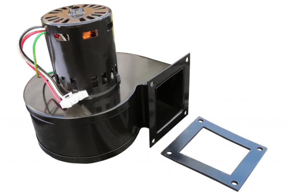 Edited 2019-11-10 08:53 by Warpspeed Cheers, ĀTony. |
||||
| mackoffgrid Guru Joined: 13/03/2017 Location: AustraliaPosts: 460 |
Mark, That peltier device is cool (pun intended)  It could work and it's not that expensive. On a power budget to cooling effect it's nowhere near as good as a proper Aircon. We only need to get the temperature down to a reasonable temp. So in reality a good forced air solution is all we should need, as per Tony's post. |
||||
| Warpspeed Guru Joined: 09/08/2007 Location: AustraliaPosts: 4406 |
 Here is are some fairly typical performance curves for a peltier device. In this case the max rated power would be at the maximum rated input current 1.0 to the right of the X axis. You will also see that as soon as the delta T (hot temp-cold temp) is more than about ten degrees, the performance shrinks down to nothing. The best I could do with a low cost Chinese peltier was to run it at about five percent of full rated power, and keep delta T below about twenty Celsius. Under those conditions I could measure something like two watts of dc power input, three watts of heat dissipated on the hot side and one watt of absorbed heat on the cold side. ĀThat was for a forty watt rated device ! Any attempt to pump more power into it caused the hot side heat to conduct through the device onto the cold side. ĀThe hot side becomes a LOT hotter, and the cold side temperature also becomes warmer, not colder. Now you may not believe this, but try it for yourself and see. You buy something that says 40 watts max power. Peak efficiency 70%. And from that you might assume 28 watts of cooling is possible. Wrong ! the 70% will probably be measured at zero temperature differential and a couple of watts input. And the 40 watts input, the point of actual device failure, not how you can run it. But they don't tell you any of that. Here is what I finally ended up with, pretty much like that e-bay cooler I think. Altogether a giant disappointment and complete waste of time. Nowhere in that e-bay add does it specify any cooling capacity or temperature drop, there just might be a reason for that. 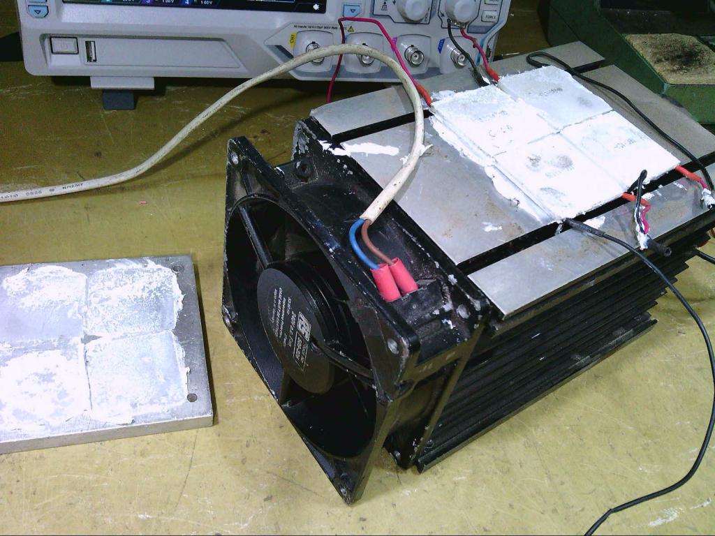 Edited 2019-11-10 12:57 by Warpspeed Cheers, ĀTony. |
||||
| renewableMark Guru Joined: 09/12/2017 Location: AustraliaPosts: 1678 |
I see, probably why they have switched to water cooling. I'll keep an eye out for a broken central heating unit dumped on the street. Cheers Caveman Mark Off grid eastern Melb |
||||
| Warpspeed Guru Joined: 09/08/2007 Location: AustraliaPosts: 4406 |
I use the blower out of a Rinai gas space heater. Heaps of air and its almost silent. Cheers, ĀTony. |
||||
| BenandAmber Guru Joined: 16/02/2019 Location: United StatesPosts: 961 |
A window air conditioner unit is very cheap here in the US even cheaper if you buy it in the winter time I've seen new 5000 BTU units go for as low as 60 bucks They use in between 250 to 500 watts on average These small ones are very easy to start also without a very big surge I've been thinking about trying to find a model that has a rather large condenser and adding a reversing valve(heat pump) Something like this would be so simple for anyone of you guys to add an external thermostat and automatic control their circuitry is so simple compared to what you guys do it would be very easily encased in such a way you wouldn't have to cut a hole out in your wall be warned i am good parrot but Dumber than a box of rocks |
||||
| BenandAmber Guru Joined: 16/02/2019 Location: United StatesPosts: 961 |
As far as fans for cooling you should take a look at what Sean ( power jack repair guy) is doing He installs and sells what he calls a fan upgrade kit for power jack inverters Rumor has it you have to be very careful how you install your inverter because the daggone thing just might take flight I keep telling him exactly what all you guys have taught me The Transformers are just way too small he has had some success at more power and reliability by running enough fan power to make them take flight I have aggravated him enough to where he has done a test for himself He is supposed to upload the video to his YouTube soon On this video he takes a 1500 watt power jack inverter and put a 8000 what power jack Transformer in it He then keeps adding more load until it blows I predicted from reading all the wisdom from you guys on here that it would do the true rating of the Transformer Gentrysolar is his YouTube channel he has crap loads of videos on Power Jack He's a pretty good Feller he's starting to do really cool videos like the one I just described Sorry for butting into you guys's discussion be warned i am good parrot but Dumber than a box of rocks |
||||
| noneyabussiness Guru Joined: 31/07/2017 Location: AustraliaPosts: 506 |
https://rover.ebay.com/rover/0/0/0?mpre=https%3A%2F%2Fwww.ebay.com.au%2Fulk%2Fitm%2F263757272788 I use 2 of these in push pull config in mine, i salvaged mine from an old server by accident. 4 wire, VERY easy pwm wire, if grounded almost silent, however full noise will suck a golf ball through a garden hose. Has all the specs in datasheet. Works well with a tl350 and arduino temp control. I think it works !! |
||||
| Warpspeed Guru Joined: 09/08/2007 Location: AustraliaPosts: 4406 |
That Radiospares fan on the big heatsink in the above picture looks like an ordinary computer fan, but as you can see its actually 230v ac, and it blows a real hurricane. Good capable fans and blowers are out there, and often for free. Cheers, ĀTony. |
||||
| renewableMark Guru Joined: 09/12/2017 Location: AustraliaPosts: 1678 |
I got the second winding on. Went to do the lightbulb test with mains power. the switch in my little rig broke so I just shorted out the connections that normally went to the switch, so basically the light wasn't in series anymore, ie no soft start. Anyway it didn't trip the breakers, the light did a split second flash and went out. exact voltage across both, so will goop it up and get ready for the third winding. Clamped it at 0.062A AC Cheers Caveman Mark Off grid eastern Melb |
||||
| Warpspeed Guru Joined: 09/08/2007 Location: AustraliaPosts: 4406 |
That is excellent, around 14.5 watts idling power. Cheers, ĀTony. |
||||
| renewableMark Guru Joined: 09/12/2017 Location: AustraliaPosts: 1678 |
As the second winding had to overlap, the finish of that winding was further around the torroid to the rest of the start finish wires. So it got a clear plastic insulation pipe and just taped it back to the start area, so easy connections can be made. As it's on the outside this makes zero difference to the torroids operation correct? 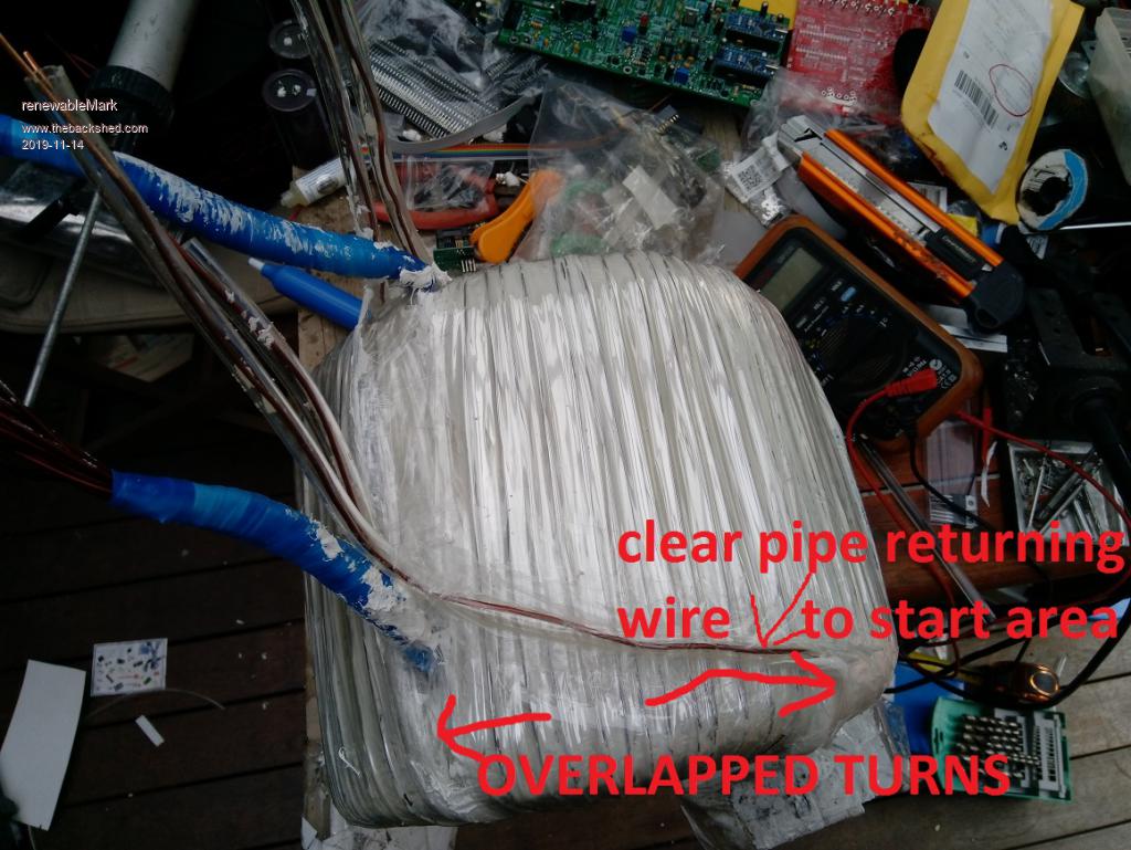 Cheers Caveman Mark Off grid eastern Melb |
||||
