
|
|
Forum Index : Electronics : Mack-OffGrid’s 26.5 Volt Warpverter
| Author | Message | ||||
| Warpspeed Guru Joined: 09/08/2007 Location: AustraliaPosts: 4406 |
There are really two separate issues for soft starting, bringing the electrolytics up to voltage, and soft starting the inverter into the transformers. My Warpverter control board bursts fully into life pretty instantly as soon as the dc supply reaches about +35v. The electronics have no soft start as such, but at that voltage the transformers are only being driven by about a third of their normal voltage anyway, so its not an issue. Andrew's control board is rather different in that there is a delay between initial power up of the electronics, and when pushing the start button actually starts all the action. By that time, the main electrolytics will be at their full voltage, so an electronic soft start is required to prevent any residual transformer inrush surge. I have a soft start button fitted to my battery isolation circuit breaker. This closes a double pole relay, with a 30 ohm 200 watt metal clad resistor on the positive side only. I usually start up the inverter direct from solar, which is inherently current limited by closing all my solar panel circuit breakers in sequence. I only ever start up the inverter from battery at night, and that is why I have soft start on just the battery. Cheers, �Tony. |
||||
mackoffgrid Guru Joined: 13/03/2017 Location: AustraliaPosts: 460 |
Mosfet H-Bridge board and Driver Further to the discussion about the Inverter Module, drilling down, are the MOSFET H-Bridge boards and Driver boards. There is very little to the Mosfet H-Bridge board. Having said that, quite a bit of thought went into it. Github - Full Bridge ZIP FIle (Gerbers / CAD) 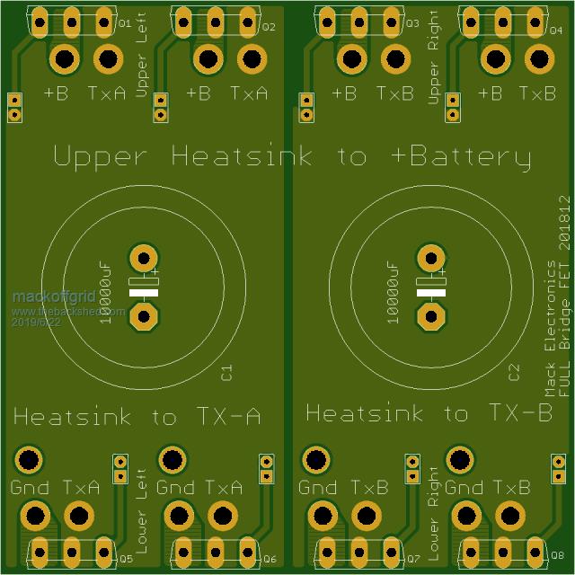 Bottom Layer 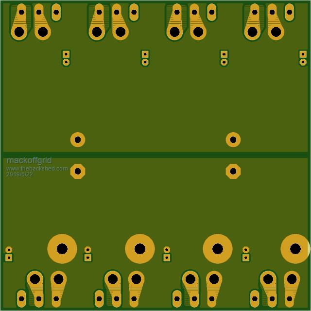 I'm quite the fan of the very low cost 100mmx100mm PCBs. So..... The PCB is a standard 100x100mm 1oz PCB. I don't have the calculations anymore but I did calculate the currents and temperature rises and determined that 1oz copper was fine. This PCB can be used for either a Full Bridge PCB or a Half Bridge board, it just depends on what drives the Gates. I have both Full Bridge Driver PCBs and Half Bridge PCB. This board is designed, as the pcb Overlay suggests, to connect the +ve feed, and the transformer legs, via the Mosfet's heatsink. I also made provision to solder 6mm2 wires in close proximity to the Mosfets pins for GNDs, +Battery, and the Transformer Legs - if necessary. There are also four additional holes (GND ) for either wire connection or if you look at the bottom layer you'll note that you could solder a brass standoff to connect to a buss. (Or screw down to a brass standoff). As you can see in the prior post that I opted for 4mm wires as a GND connection. I wanted as few components on this PCB as possible to maximise the copper for current paths. I also wanted to minimise the current path to large capacitors. The two pin header connectors are the only extra components on this pcb apart from Mosfets, Large capacitors and Gnd connecting wires. The two pin header connectors, one per Mosfet, is Mosfet source and Mosfet Gate. The Driver board plugs into these header pins. One change I would consider is to have a SMD 100k resistor from gate to Source on every Mosfet. It would make almost no difference to the copper area - current paths and provides a pull down in case the board is powered up without the drive board plugged in - in this case the Mosfet will almost certainly let the smoke out. When you have 40 Mosfets the pull-downs need to be reasonably high value. The bottom side of the driver board on the left. 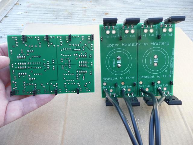 This image shows the capacitor loaded underneath the Mosfet Board and the driver board plugged in. 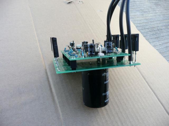 If you're not already bored by the detail, I'll talk about the driver board in another post. Cheers Andrew |
||||
| BenandAmber Guru Joined: 16/02/2019 Location: United StatesPosts: 961 |
Please do talk about the driver board be warned i am good parrot but Dumber than a box of rocks |
||||
| Warpspeed Guru Joined: 09/08/2007 Location: AustraliaPosts: 4406 |
A very neat and efficient layout Andrew. Cheers, �Tony. |
||||
| Tinker Guru Joined: 07/11/2007 Location: AustraliaPosts: 1904 |
There appear to be a lot more components on your driver board than are on mine. Can you post a top picture so I can see what is where and how you fitted those isolated power supplies? Klaus |
||||
| mackoffgrid Guru Joined: 13/03/2017 Location: AustraliaPosts: 460 |
There are Klaus, but no big surprises. I'll do another post soon. I look forward to hearing how you go with the Anderson connectors, are they proper Anderson brand or are they a copy? I like the idea if they work well enough. Arthur, those caps look good  |
||||
renewableMark Guru Joined: 09/12/2017 Location: AustraliaPosts: 1678 |
Yes, lots of detail please. I'll probably copy your layout, but flip it to fit in a locker. Andersons..... well they use them on forklifts, they pull plenty of amps. Cheers Caveman Mark Off grid eastern Melb |
||||
| Tinker Guru Joined: 07/11/2007 Location: AustraliaPosts: 1904 |
The Anderson plug idea occurred to me when I stumbled upon the pair that was residing on my shelf  . .There are a lot on offer on ebay, some are only 24v rated. These connectors are 600V rated and accept 50mmsq cable, should be plenty for the average <8KW inverter. Just make sure they are not disconnected under load  . .Klaus |
||||
| renewableMark Guru Joined: 09/12/2017 Location: AustraliaPosts: 1678 |
Probably better to go a bit heavier like this Cheers Caveman Mark Off grid eastern Melb |
||||
| Warpspeed Guru Joined: 09/08/2007 Location: AustraliaPosts: 4406 |
The various voltage ratings are really a fiction. The different colours are supposed to represent different voltages, and they are keyed differently. So only the same colours will plug into each other. The physical sizes, insulation, and construction are the same (within a size class) so you can ignore the voltage rating and just buy the plugs of whatever colour you decide to use. I have red, grey, and blue here, and its a real bugger. Should have stuck to just the one colour so I can plug whatever cables I have into wherever I wish to plug them. Not entirely happy with the Anderson plugs..... They pull apart (fall out) far too readily, and sometimes do not make good contact and then the plastic melts. If you do splat the contacts, they are never quite the same again and can then tend to run hot under load and melt down. They have a convenience value I suppose, but for fixed permanently installed equipment, they would not be my first choice. Bolted lugs for me in the future. If I absolutely needed a very high current plug and socket I would seriously consider the common welder plugs, available in various sizes and colours. These push in and twist lock very solidly. A much more serious type of connector, they make Anderson plugs look like fragile children's toys. This is probably not a fair comparison, 50A Anderson plugs versus 300A welding plug. Note the different keying on the Anderson connectors. 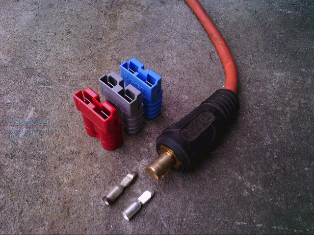 Cheers, �Tony. |
||||
| mackoffgrid Guru Joined: 13/03/2017 Location: AustraliaPosts: 460 |
Driver Board - Full Bridge In this post I will describe the Full Bridge Driver board (and revisions), when used in single board H-bridge, I'll leave the multi-board H-bridge for another post as it is more involved. As mentioned in the first post, this inverter is my learning platform and so the driver boards have had extra circuitry on them so I could try different things out. As it turns out, to no surprise, Tony's circuit was pretty much what I settled on for driving my Fet boards. I've always been a fan of opto-isolated gate drivers and my goto is the TLP250 which is kind of a lower powered version of the 3120. I'm not fond of charge pump circuits but plenty of the Ozinverter guys have them working so who am I to judge. If I were to build a Ozinverter I would have used TLP250 etc and have isolated power supplies. That's just me. Interesting to see that Mike "Wiseguy" is going the same way. When I saw Tony's method of interlocking the opto-isolaters and incorporating the dead-time using the 10nF cap I immediately appreciated the simplicity and cleverness of the idea. I seem to be on the same page as Tony on almost everything concerning this project. I do use Molex connectors where Tony uses Plugin terminal blocks, that's just because my background is different to Tony's but I have preserved the pin order or numbering. One slight addition I made is to add a speed-up diode to turn the Fet off. I find this useful as I play around with the values of the Gate resistor (Rg) and still have the turnoff happen in a timely manner. Below is a simplified schematic. 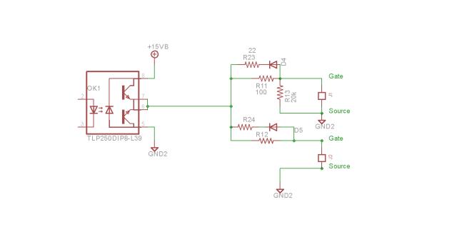 The Driver board I'm using is shown below. I drew this pcb a months ago to test some particular ideas which I didn't bother with including driving the gate down to -5 volts. I did include those little 1 Watt 12-15 volt isolated converters. A little mod (see the little wire) and it is equivalent to the schematic above. 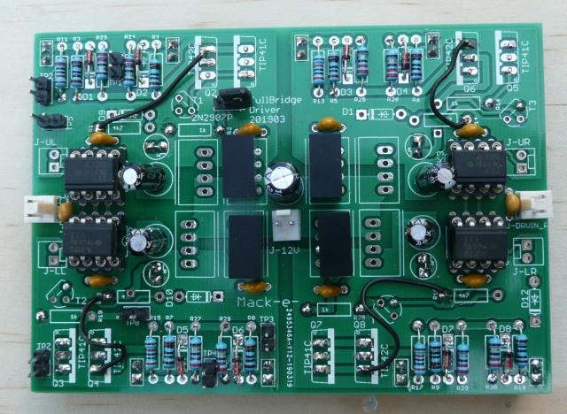 As you may notice I tested the totem pole, driving down to -5 volts, this works fine and I do like the totem pole as it introduces a soft undershoot that I tend to prefer in slow speed applications like this. It was just unnecessary. The reason I was experimenting so much is that I was trying, so, so, much, not to need a choke in the transformer leg. So I was trying to control the speed of the FET turn on at low load. This can be achieved but it was so much trouble that at the end of the day a choke was simply the answer. Image below shows how it interconnects 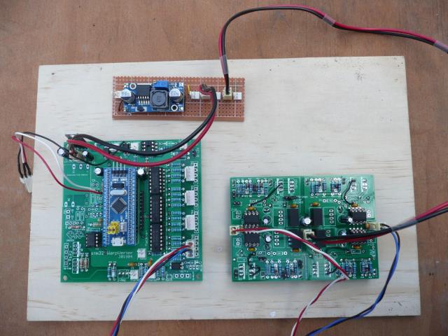 So you can see from this image that non-isolated 12 volts (supplied by the cheap buck converter) connects to the middle of the driver board where it feeds the four isolated 12-15v converters. The stm32Warpverter board is on the left, it could very well be Tony's stepInverter board except his board has plugin terminal blocks whereas the stm32Warpverter can have either plugin terminal blocks or the molex connector. You can see the cable connecting into one of the driver outputs (Large - as it happens) and splitting up into left and right side driver inputs. I always use this colour coding as shown in the photo, with the red-white on the left, blue-black on the right. In my inverter, you plug the driver board onto the Fet board so that you can read the print on the board (board title etc) the right way up. For reference, The driver connector on the stm32_Warpverter goes from the top, Red-White-Black-Blue. 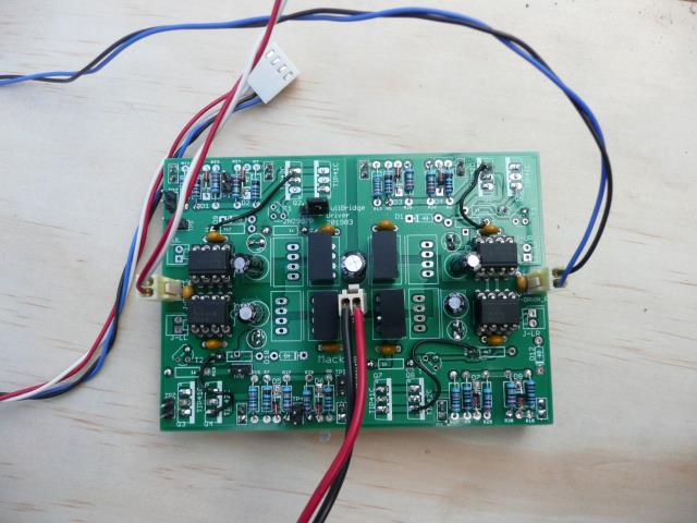 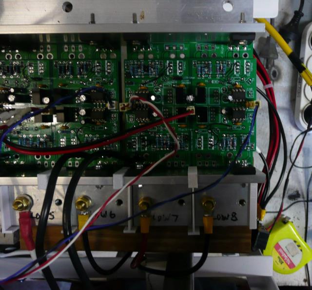 Older Driver Board This is the board you saw in the last post that was plugged into the Fet board. Warpverter FullBridge Driver 201811, Cad and Gerbers 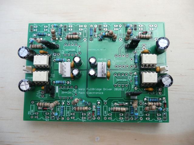 This board has the same elements as in the first simple schematic I showed. It does not have a power supply, isolated +15 has to be provided externally via those two four pin molex connectors. Don't worry about the ugly way I was using 2 resistors together, its not a mod, just a simple way of changing Rg. This board has an extra driver IC IR4428. This has two purposes. If used it can drive a clamping FET IRFD120 (those 4 pin dip parts), which hard clamps the gate to source. Nice but didn't add anything to this project. The second function is to do with coupling multiple drivers together. Cover that later. The four jumpers bypass's the IR4428. The overlay shows the default position. This is the board to use if you are providing an external power supply. Gate Resistor and speedup I experimented with Rg values from 22R to 1kR. All worked. I found 100R to be a nice value, as suggested by Tony. There is little to be gained by driving the mosfets hard except increase noise and power required. The benefits of Rg=100R is that the TLP250 is not stressed at all, no driver over shoot which increases noise through the TLP250 back to the controls. Much reduced risk of driver failure if you do get a mosfet failure. Easier on the headers and on the little iso-converters. I do prefer to have the speed up turnoff diode-resistor just to make sure it turns off in time. 22R is a nice gentle value. Well, that's a lot of talk on a simple circuit - complex subject though, not even touched on the many issues of driving Mosfets in a H-bridge. Cheers Andrew |
||||
| BenandAmber Guru Joined: 16/02/2019 Location: United StatesPosts: 961 |
I'm glad the welding plugs get your approval warp-speed that's what I purchased for a quick connect 4 the inverter in my RV I have several Anderson plugs lying around I do not trust them even though they came out of a 48 volt APC inverter While goofing around here at the house I used them for testing the little inverter and the splat just ruins them I have had the exact same experiences as you with these plugs be warned i am good parrot but Dumber than a box of rocks |
||||
| Warpspeed Guru Joined: 09/08/2007 Location: AustraliaPosts: 4406 |
I have heard these same complaints before from others Ben, we are not alone... Andrew, we do seem to think pretty much alike. I have tried a few different ideas too, and came to very similar conclusions that simplicity is a definite virtue. And it can all work quite nicely with very few parts or frills. I did not worry too much about controlling switching speeds, and dead time can be made pretty wide too, without any associated problems. The main point of difference between our approaches is how each fet driver board is powered. I was able to get away with running the "guts" from ordinary mains powered plug packs very successfully, and that is still the simplest solution for +100v dc inverter. At +24 volts dc, that is a definite non starter, so a completely different isolated dc power supply system is required. A +48v inverter is kind of in the middle and could go either way. There are four isolated gate driver supplies required for each inverter, and four inverters, so whatever you use there will be sixteen of them, and cost and efficiency starts to become a factor. The seventeen (16+control board) postage stamp sized supplies I use, draw a total of almost exactly 5 watts, which is all of the dc power for everything actually running, without any transformers or fans connected of course. But it can make up a significant proportion of the final total idling power, so its well worth taking the trouble to plan it all out very carefully. Cheers, �Tony. |
||||
| mackoffgrid Guru Joined: 13/03/2017 Location: AustraliaPosts: 460 |
I actually made a power supply with 16 isolated outputs. Well one output was 14v and another was 17 volts ..... I guess I don't count too well.  Plenty of power but it was just too much, wires, and everything. Plenty of power but it was just too much, wires, and everything. So I'm using those little 1 watt converters. They're very neat. But given the choice I'd go the bigger converter like you are using. I find I'm using about 1 watt per 4 power supplies / so 4 watts for the lot, in the same ball park as you. The other thing I forgot to mention, dumb thing. Those Driver boards marked 201812 have pulldowns on every FET and labelled at 1k each. Well, the bottom quadrant pulldowns got hot, and then just prior to the head-slap, realised they were pulling a truck load of power. So I cut out every pulldown but one per quadrant and changed them to 20k.Cheers Andrew |
||||
| Warpspeed Guru Joined: 09/08/2007 Location: AustraliaPosts: 4406 |
[quote] I find I'm using about 1 watt per 4 power supplies / so 4 watts for the lot, in the same ball park as you.[/quote] Probably identical. My control board draws 25mA at +5v and at any one time about eight of the sixteen opto isolators are switched on, each drawing 10mA. That is about 100mA and half a watt (at +5v) and probably twice that at the input of the 100v to 5v dc/dc power supply. So about four watts for the four inverters, plus one extra watt for the control board. My overall idling power runs about 30 watts. Not that much different to a good PWM inverter. Cheers, �Tony. |
||||
| Tinker Guru Joined: 07/11/2007 Location: AustraliaPosts: 1904 |
So I had a look at them of what is on offer on ebay. They are cheap enough... But, I do not like the exposed brass at the plug, too easy to short with something when disconnected. One also needs to have separate colors for pos. & neg. *and* make sure they get plugged correctly. Brass is not a very good conductor, OK for the short high current bursts when welding but I wonder how they perform when connected 24/7/365 at an inverter. So I'll try the Andersens. Not possible to connect them wrong way round. Only one plug. Keeping in mind that after initial testing they would be only handled when there is an inverter failure (to change over to the spare inverter). Done correctly there is only the tiniest spark (hard to see) which will do no damage at all to a 175Amp Andersen. My existing inverters have Copper bolt & brass nut battery connections. This can be a pain as one has to be ever so careful the spanner does not short out to the adjacent terminal bolt accidentally, like when slipping off the nut perhaps. Klaus |
||||
| Warpspeed Guru Joined: 09/08/2007 Location: AustraliaPosts: 4406 |
Haha, been there done that too, with very similar results. Fished this out of my failed projects graveyard.  Cheers, �Tony. |
||||
| mackoffgrid Guru Joined: 13/03/2017 Location: AustraliaPosts: 460 |
I'll do a post on the multi-Mosfet board setup in another post but I thought I'd post about transformer winding capacitance. Transformer Winding Capacitance Warning some images may scare you. Don't worry its all good When I was first testing the various boards, I was using only small wires and probably a limiting resistor. The output looked nice. I think this output must be using 3 transformers. 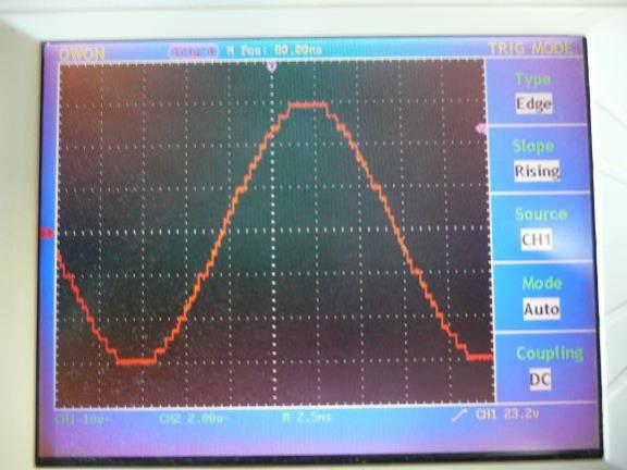 Then I put it all together with big cables buss bars etc and the output had these big spikes. Capacitors made it even worse. Showing output at no load 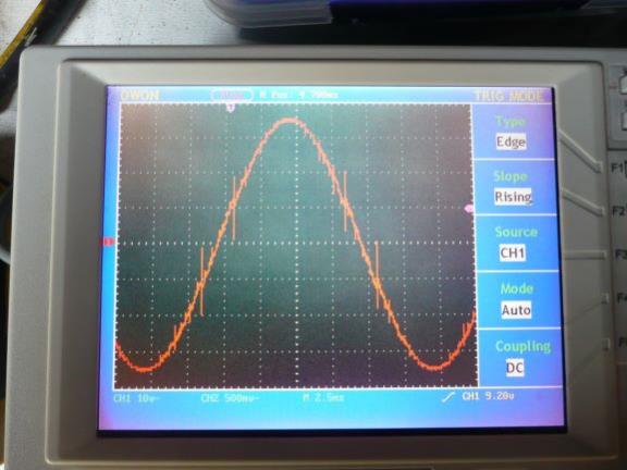 Showing output at 500W 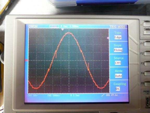 So I disconnected all the transformers except the large one. Showing the output of single transformer. 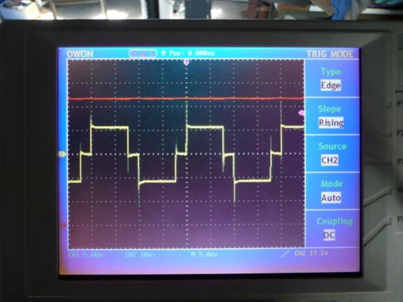 And drilling down to the spike. 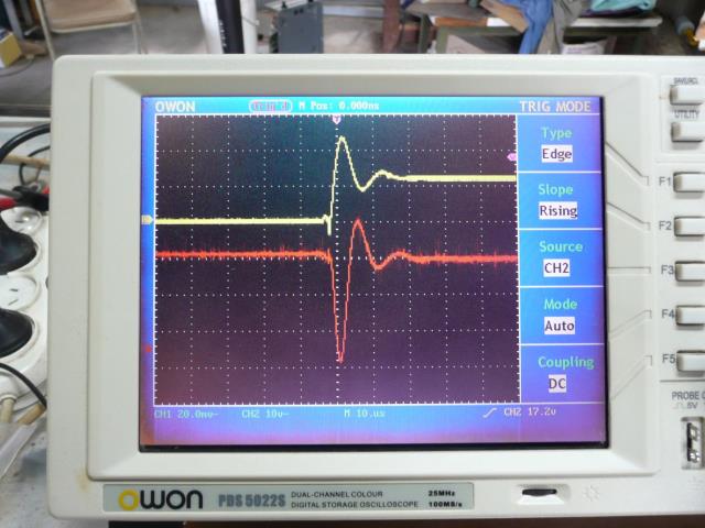 The yellow trace is the transformer output, thats a 230 Volt step. The red trace is the output (sorry - its inverted) of a Hantek current clamp 1mV/Amp. The frequency response is meant to be 100kHz I think, so while this is showing 60 amps, it could be somewhat larger. In this test C=44,000uF two Mosfets per Quadrant. Another example. The following image shows the supply rail with zero capacitors and just 2 mosfets per quadrant. The supply is connect via 35mm2 cables to fully charge gel cells. That's a 10 volt spike in a 24 Volt system. 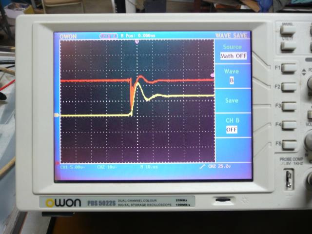 Yellow trace is the transformer output Red trace is the 24V supply buss. Well an email to Tony confirmed my thoughts that it must be Transformer Capacitance. I was confused because I thought transformers were inductive devices  As I said in a previous post I was trying to avoid a choke and tried a bunch of ideas but in the end a choke is what it needed. Now with a test choke of 60uH (80 watt soldering iron as load) 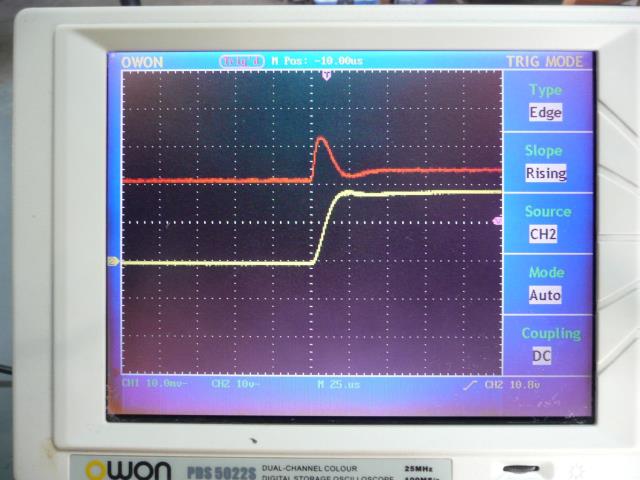 Much nicer. and 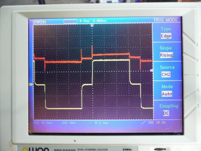 Next I connected all the transformers up and now there is a current spike coming from Transformer no2, only when it does the positive to negative (or vice-versa) transition. Added this AeroSharp 2x20A choke, configured into a 40 Amp choke. 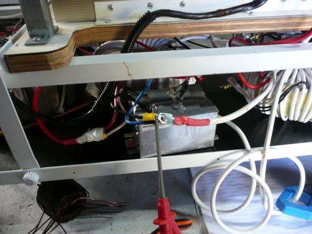 and gives us this output. 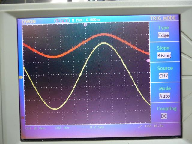 Yellow trace is the output voltage. Red trace is the current clamp on either the No1 or No2 Tx primary. (can't remember) All basic stuff. All Good. Cheers Andrew |
||||
| Warpspeed Guru Joined: 09/08/2007 Location: AustraliaPosts: 4406 |
Excellent Andrew. That is identical to what my inverter looks like with just the three transformers and three inverters running. 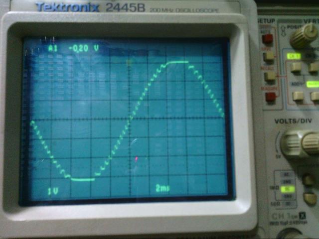 The fourth inverter makes an incredible difference to the final smoothness of the output. Again that looks identical to what I am seeing with all four inverters and transformers running. I never had the spike problem, probably because my transformers are E and I lamination type, not a toroid, so the winding capacitance will be far less. But its really good to know that there is a simple choke cure for that problem if it arises. Cheers, �Tony. |
||||
| mackoffgrid Guru Joined: 13/03/2017 Location: AustraliaPosts: 460 |
Tony, I do have a question. I am now, quite happy that I have a choke/s in the circuit as it does provide a degree of protection, could even lead to a current protection circuit. Having said that, my current chokes role is to only smooth out the current required to charge the transformers capacitance. The choke I am building will have a high sauration but it need not. If I was to get fancy, you could design two chokes in series where I have one. One choke (ferrite E-core, E60?, foil) at 1mH that is designed to saturate at say 20 amps and another smaller choke at 20uH but saturates > max designed current (300Amps?). The 1mH choke makes the no-low load output look nice and pretty but it is too much inductance when you're driving big loads. But some inductance is still desirable, this can allow current overload detection if we want. What happens to the saturated ferrite core? Does it get hot. My guess is that it doesn't because the ACripple is low frequency. cheers Andrew |
||||
