
|
|
Forum Index : Electronics : Mack-OffGrid’s 26.5 Volt Warpverter
| Author | Message | ||||
| Warpspeed Guru Joined: 09/08/2007 Location: AustraliaPosts: 4406 |
Dc saturation will not make a choke get hot, just all of the inductance goes away. Now you could build a "swinging choke" that has high inductance at low dc current, and the inductance falls as the dc current rises. If you look at something like that on an inductance tester, the rate of current rise will not be a linear ramp, but will be a very shallow upward sweeping curve that starts out with very little slope, but the slope gets increasingly steeper as the dc current rises. Two ways to do it. One is to use a powdered iron core which have a natural very soft saturation characteristic. Or you can use a much lower cost steel core, and there is a trick with the air gap. The air gap spacer you use is not a flat fixed thickness spacer, its more like a wedge. Thin at one side, and thicker at the other. That tilts the core halves slightly crooked with respect to each other, but not by much. The clever thing about that, is that the thin edge of the wedge acts like a very small air gap producing a high inductance. As the dc current increases, the thin edge of the wedge saturates, but the part with a wider air gap keeps on working right up to full dc saturation. So instead of seeing a constant rate of current rise on your inductance tester with a very abrupt saturation limit, its a concave curve that very gradually gets steeper and steeper as the dc current rises. You can play with the wedge shape, as the thin end and thick end can be independently adjusted to get the kind of inductance range versus dc current that is required. Cheers, �Tony. |
||||
mackoffgrid Guru Joined: 13/03/2017 Location: AustraliaPosts: 460 |
Thanks, again I learnt something new. Is it crazy to use a small wedge of ordinary steel along with shaped plastic to fit into an existing choke? |
||||
| Warpspeed Guru Joined: 09/08/2007 Location: AustraliaPosts: 4406 |
The air gap cannot be steel, whatever forms the gap must be non magnetic. Cheers, �Tony. |
||||
| mackoffgrid Guru Joined: 13/03/2017 Location: AustraliaPosts: 460 |
Tony, I didn't communicate that clearly. If I have an existing choke and a wedge shape gap spacer can't be fitted; that I provide a wedge piece of steel (garden variety) to extend the face of the core in a wedge shape and make a plastic gap spacer to fit. I imagine standard steel will saturate at a lower flux density which wouldn't hurt that much since it's facing the gap. Swinging Choke 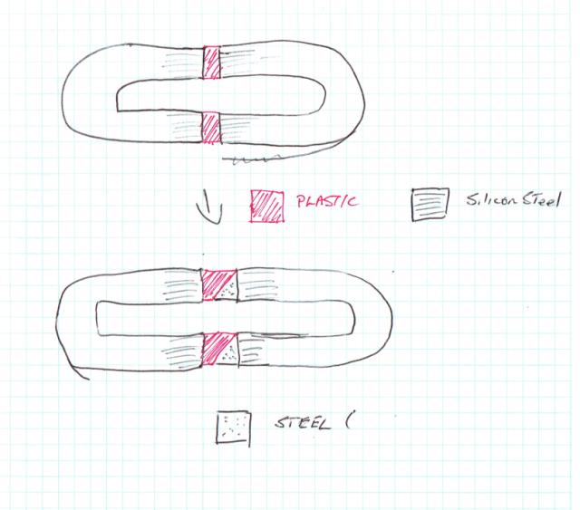 Am I wrong? Cheers Andrew |
||||
| mackoffgrid Guru Joined: 13/03/2017 Location: AustraliaPosts: 460 |
Safely Testing the Inverter Module I needed a safe way to test the Inverter Module for dumb mistakes I can manage from time to time. Adding a resistive supply feed is not going to work if you can't remove the huge capacitors. My Procedure - Transformers and Battery feeds are not connected. - I supply the Warpverter controller and driver boards with there own power supply. - I use one of those CVCC LM2596 (3 pots) power supplies to power the Inverter Modules rails to 4 Volts, with the current limit set to < 1 Amp. These modules are very useful as they tolerate short circuits. I don't know at what voltage my capacitors (190,000uF) are lethal to the mosfets but 4 Volts were safe. You could attempt to work it out but I'm not going to bother. - Use the output drive for the Large Transformer to test each driver and use a 1k resistor instead of transformer. Use your scope to see the output is fine and the LM2596CCCV module will also tell you if something is wrong. This has saved me at least once. Cheers Andrew |
||||
| Warpspeed Guru Joined: 09/08/2007 Location: AustraliaPosts: 4406 |
Ah, it suddenly becomes clear now, I understand your reference to a steel wedge. There is an easier way to do it. Here is a cartoonish parody of a giant air gap wedge. 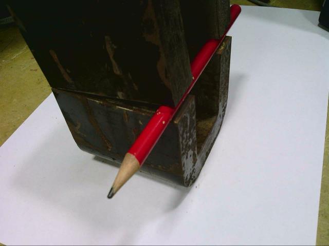 The real wedge might be only 1mm or 2mm thick, and will go unnoticed when the choke halves are finally assembled. Cheers, �Tony. |
||||
| Warpspeed Guru Joined: 09/08/2007 Location: AustraliaPosts: 4406 |
That all sounds very good advice Andrew. Its all pretty benign, the greatest mosfet killer at startup is cross conduction, and the inverse parallel opto driver design guarantees that can never happen. Only trap for the unwary is that the opto gate driver chips have an undervoltage lockout, and the +15v gate driver supply needs to be there almost in full, or the gate drivers may refuse to work. A very cautious power up procedure may prevent the gate drivers from receiving enough supply voltage and working. So if the whole thing appears dead, there just may not be enough dc voltage supply to wake up the gate driver chips. If the upper/lower opto drive is reversed to each half bridge board, it will work fine, as long as all of the half bridge boards are wired up exactly the same way around. Nothing is going to blow up if you mix up the opto drive wires, but the inverter output waveforms will probably go completely weird. Get the whole thing running first without any transformer loads. I would start with a resistive load on each inverter, and see that all is well. Then try each inverter with the smallest transformer as a load first, and progressively work up until each inverter has its correct transfomer fitted. Last step may require one or more of the transformer primary or secondary connections to be reversed so that all four waveforms add up together in the correct way. Cheers, �Tony. |
||||
| mackoffgrid Guru Joined: 13/03/2017 Location: AustraliaPosts: 460 |
Starting - (Soft Start) I have pretty much always done hard starting but by the time I stiffened up all my buss's, leads and capacitors I found I was blowing Mosfets on startup IF I only had one Mosfet per quadrant driving the big transformer. At this stage I didn't have a choke in the circuit. Two Mosfets per quadrant handled it okay. I added a soft start to the stm32_Warpverter and no more Mosfet fatalities on startup when driving the large transformer with only one Mosfet per quadrant. I only blew 2 Mosfets during this experience and the second was testing Einstein's definition of insanity. My little story should come a no surprise after reading the post on Transformer Winding Capacitance and I presume the choke I've inserted into the circuit also would have solved the problem. Cheers Andrew |
||||
| Warpspeed Guru Joined: 09/08/2007 Location: AustraliaPosts: 4406 |
I usually start my inverter by switching in solar power first. That is inherently current limited and the dc supply charges the main inverter electrolytics in just a couple of seconds. If I have to cold start the inverter at nigh off battery, there is a thirty ohm 200 watt startup resistor to pre charge the electrolytics in the inverter, before I can close the battery isolation circuit breaker. Either way no dramas, and so far nothing has ever blown up. Cheers, �Tony. |
||||
| mackoffgrid Guru Joined: 13/03/2017 Location: AustraliaPosts: 460 |
Yes, solar panels are wonderful things, natural chargers. One mosfet per quadrant isn't a realistic switching capacity for the main transformer, two or more were never bothered. It was just a good show on how effective soft start is. As I said, not tested but the choke should achieve the same result. |
||||
| mackoffgrid Guru Joined: 13/03/2017 Location: AustraliaPosts: 460 |
Transformer Polarity Transformer Polarity is important with the WarpInverter. We have four transformers, some are adding voltage and some could be subtracting voltage. So polarity matters. To show what happens when a transformer is connected in the wrong polarity. 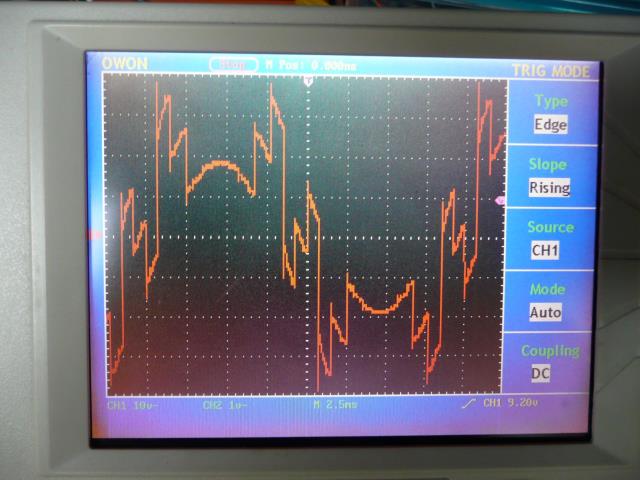 In this case the second Largest transformer was of incorrect polarity. This may cause some clicking and what not but doesn't cause any harm to the inverter. It can however destroy gear like this cheap AC power meter that uses a mains capacitor in its power supply. 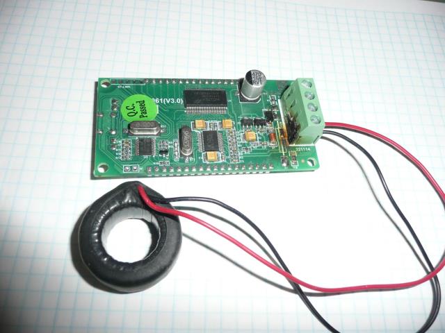 Polarity Test Setup 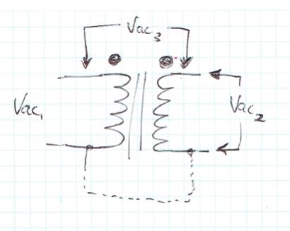 We supply a voltage into Vac1, I use a transformer (below) that's large enough to energise these transformers, but at a safe voltage like 30Vac. 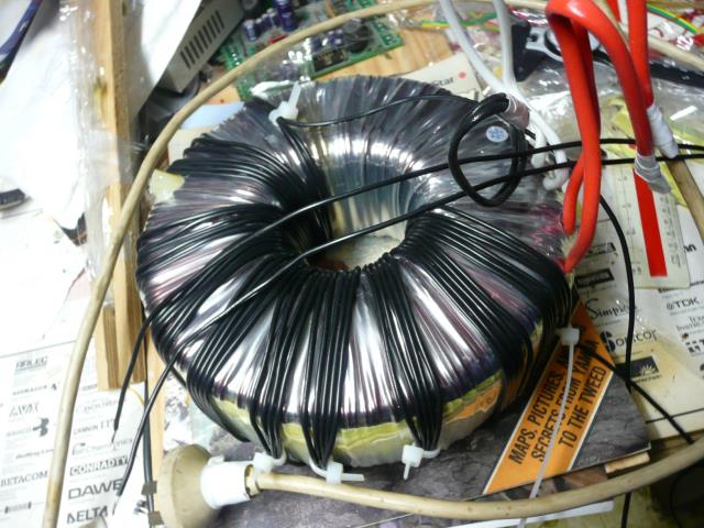 I also arrange the test so that I'm not sticking 30v in and getting 240V out. So feed in the 30V supply into the largest voltage winding. So we arbitrarily assign the dot convention, I use red heatshrink or red tape or red wire to denote the Dot end of the winding, on both primaries and secondaries. Logically I use Black for the non-Dot ends. Connect up the non-Dot end of the primary to one of the secondaries as shown in the diagram above. We know when we have matched up the Dot ends of the winding when . Vac3 = Vac1 - Vac2 Done, it's that simple. You'll note that the transformer primaries are connect Red-Black, Red-Black .... and so on. 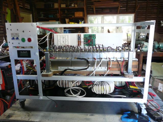 Also the secondaries are also denoted by Red and Black (well the small transformer had it's dot end marked by White tape just to be different ). This terminal block is a convenient method for me to play around with the secondaries. 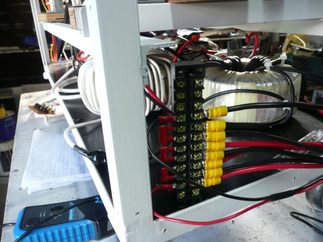 I use the same 30v transformer to check the turns ratio. Regards Andrew |
||||
| Warpspeed Guru Joined: 09/08/2007 Location: AustraliaPosts: 4406 |
The transformer phasing is not difficult to sort out, the waveforms either look good or go really strange. And its just a case of swapping a few things around until its right. Cheers, �Tony. |
||||
| mackoffgrid Guru Joined: 13/03/2017 Location: AustraliaPosts: 460 |
New versions of Mosfet PCBs and Driver PCBs available Mosfet Bridge PCB (201907) Just a heads up. I have updated the Full Bridge Mosfet Board to include (optional) SMD 100k pulldowns and have changed the 2 pin headers to 4 pin Headers. You can still put the 2 pin headers in, and is backward compatible. A 2 pin driver board will drive a 4 pin Mosfet board. I did this not because I had problems, except I found over time with all my experimenting and tossing boards about, I occasionally knocked the housing off. Put it back on and she was sweet. But I thought the 4 pin header is stronger and some redundancy would be useful. MosfetBridge_201907 Gerbers Github page Driver Board PCB (201907) 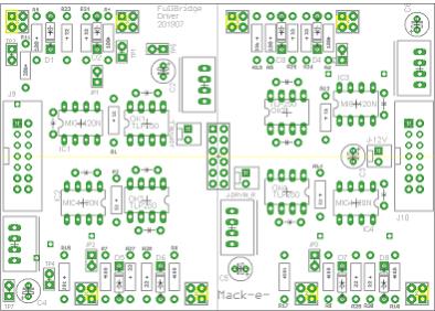 I have updated both the Half and Full Bridge driver PCBs. In my earlier versions, the means of extending driver boards like you would need to do for the Large Transformer was a little, um, messy with little cables everywhere. This was fine for me, and experimenting but I thought I would do something a little nicer and clearer. On the Full bridge Driver board I have put a IDC14 connect on the left and on the right sides of the board. I have done the same for the half bridge driver boards. As you imagine the Full bridge receives the signals from the inverter board, buffers the signal, and transmits them respectively to their LEFT or RIGHT port. Non-isolated DC and Upper/Lower Isolated DC is commonly bussed over these ports. Each Driver board has provision for Isolated PSUs. The Half bridge boards have provision for either the small 1or2 Watt or the ACDC isolated PSUs. So where you have half bridge boards connected you are probably better off omitting the PSUs on the central Full Bridge Board and let the Half Bridge driver boards feed its Iso-pwr to the Full bridge boards. The IDC14 ports are extended to both sides of the Half Bridge boards which allows them to be extended forever - sortof. 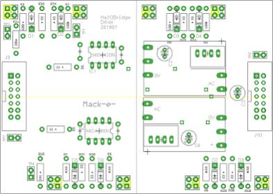 Driver PCB Github page I hit the Update Post accidentally before I was done  Cheers Andrew |
||||
renewableMark Guru Joined: 09/12/2017 Location: AustraliaPosts: 1678 |
Nice work, I'm still trying to get my head around the connections. What is the power supply on the full bridge driver board? Cheers Caveman Mark Off grid eastern Melb |
||||
| mackoffgrid Guru Joined: 13/03/2017 Location: AustraliaPosts: 460 |
The power supplies on the Full bridge board are those little DC-DC isolated converters. All supplied by the 2pin jack labelled +12V, though you can apply any appropriate voltage to suit the isolated PSU's that you're using. Link to those little converters, B1215 1Watt If you are connecting the Half Bridge boards to Full Bridge boards like you would for the large transformer, you could omit the little DC converters off the Full Bridge board, plug 48v into where it says +12v, and use the ACDC converters on the half bridge board, they will feed back to the full bridge board. You can also use the little DC-DC isolated converters on the half bridge Boards. I'll try and do a diagram over the next few days Cheers Andrew |
||||
| mackoffgrid Guru Joined: 13/03/2017 Location: AustraliaPosts: 460 |
AS promised a diagram to show the inter-connections I've included a Zip of the image file so you can get a better look at it. 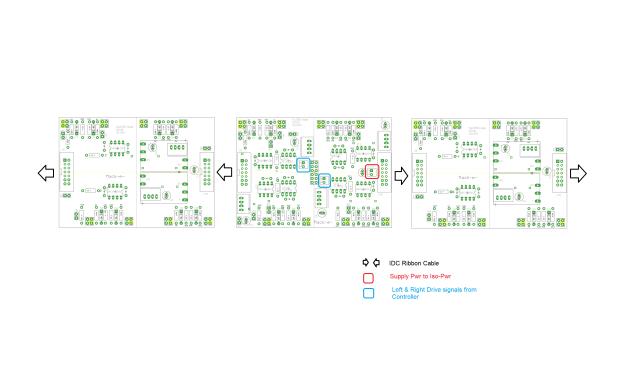 2019-07-11_212127_ThreeAmigos-D.zip +12V Molex pin 1 ------ +ve pin 2 ------ -ve Left & Right Drive Signals Controller PCB ---- Driver PCB Pin 1 ------------- Left Pin 1 Pin 2 ------------- Left Pin 2 Pin 3 ------------- Right Pin 1 Pin 4 ------------- Right Pin 2 IDC ribbon cable is 14 way. You can keep expanding Half Bridge Boards to the LEFT and RIght for as far as you want. Cheers Andrew |
||||
| Warpspeed Guru Joined: 09/08/2007 Location: AustraliaPosts: 4406 |
These come in various shapes and sizes with different input and output voltages and pin footprints, are small and can be very convenient to use. But beware. Some of these have voltage regulated outputs, and others are not voltage regulated. The unregulated types always have a minimum specified load current, and if they are run with no load, or at a very light load, the output voltage can become rather high. Another feature of these, is there is usually no current limit. They blow up if the output is overloaded, even for an instant. They are convenient to use, but before you buy a whole bunch of them, take the time to read all of the very fine print on the data sheet. The good ones are great, the bad ones can bring you some real grief. Cheers, �Tony. |
||||
| renewableMark Guru Joined: 09/12/2017 Location: AustraliaPosts: 1678 |
Now I get it, combined with looking at the top and bottom of the boards with gerber viewer it makes sense. With the 12v supply for the red connection what does that need to be rated for? Cheers Caveman Mark Off grid eastern Melb |
||||
| mackoffgrid Guru Joined: 13/03/2017 Location: AustraliaPosts: 460 |
Cool. The PDF schematics should there as well. Depends on how many driver boards in that cluster. You will generally use about 1 Watt. So you are only needing about 100mA for that connection. In my case I use about 4Watts for all my driver boards and I use a $1 LM2596 AliExpress Buck converter. I imagine, in a 48V system one of those 5W (maybe two or a slightly bigger one) ACDC converters would be used to provide a general 12V supply. Again in a >= 48V system, the driver cluster that drives the big transformer; it could be convenient to use those ACDC supplies on the Half Bridge boards, omit the little PSUs on the Full Bridge Board, and feed battery voltage into where it says 12V. I should probably call it Vin. Cheers Andrew |
||||
| renewableMark Guru Joined: 09/12/2017 Location: AustraliaPosts: 1678 |
Thanks mate. So the boards need 15v, 12v won't do? Those small footprint ACDC ones are hard to get in 15V now, probably better off using the little ones you gave a link to. Driver boards are 1 Oz? Power boards are 1 or 2 Oz? Also have you got a parts list? I can't seem to find MIC4420N  Cheers Caveman Mark Off grid eastern Melb |
||||
