
|
|
Forum Index : Solar : HWC element powered from HV PV array
| Author | Message | ||||
| Warpspeed Guru Joined: 09/08/2007 Location: AustraliaPosts: 4406 |
A higher wattage element will be able to transfer more power, especially as it must be off for some proportion of the cycling time while the capacitor recharges. I can think of a second advantage. Cycling a heating element on and off at a slow rate is going to crate a lot of heat shock and that may fatigue a low power element wound from more fragile wire. A much heavier element run at a fraction of its full rating, may be expected to be more long term reliable. Cheers, �Tony. |
||||
| Davo99 Guru Joined: 03/06/2019 Location: AustraliaPosts: 1577 |
Well yes and no. It's great in summer when I make ridiculous amounts of power every day, but of course I don't need much heat then, just need to move it from in the house to outside. In winter, not so great. The load from the AC which is the only heating I have and the Hot water is Huge. I could carry those loads in summer when I am making 70KWh+ a day ( before I added to the system I have now) but in winter when I'm USING 70 Kwh a day and making 12 to 30, it's a different story. When one considers a Liter of oil contains about 10 KWH worth of energy, electricity is not so great for heating. I have been looking at these small Chinese Diesel heaters. They do 5 KWH output but actually have losses in the exhaust that could be recovered. They run about 600Ml of Diesel an hour. Diesel here would average about $1.40 Litre. That makes about .17C KWH. Electricity here is .30C Kwh so the diesel heater would be about half the cost to run. Of course back in the days when I was Making Biodiesel, I could knock that out for about .27C a litre. I'd guess that might be up to about .40C litre now. Lets call it .50 for good measure. At that price If I do low conversion Bio which will make it cheaper, I'm down to around .09C Kwh to heat the place so well in front. Of course I'm working on the delivered heat not the generated so If I made a simple heat exchanger and recovered .50% of the exhaust heat.... Better off still. 5KW would be enough to keep my house warm although it would have to go longish hours. None the less, with these things available for around $150, return on investment would be a couple of weeks. I have seen the cloud edge effect a number of times now. There is a haze in the sky but the generation goes Nuts. Tends to push voltage really high for not so off the charts wattage. Not sure how that works but it clearly does. The problem I have had of late is 20Kw+ of panels producing a total of 12 Kwh for the day. I could cove my whole little acre with panels at that rate and still struggle to keep up. It is an interesting look at the difficulties of off grid that for sure. Clearly one needs as many non electric energy sources or to live in a temperate place to start. Start building this project and you will not regret it! The magic is in the caps + control program Yes I'd like to do that. Just waiting for the final version to be drawn up and testing to be completed. In the mean time I have put up a couple more arrays to match heating elements and the results are universally poor. A device of this nature is essential for any meaningful production certainly in winter. I put these arrays up, play with them a few days then realise the pathetic output for the power available and hook them to a GTI and see the KWH boost straight away. Having pulled over 1000KWH from the grid in the last 6 Weeks, I can't afford to experiment right now. Need to get the most out of all the panels I have. Had another reasonable Frost this morning but Hopefully the day will be sunny. Of Course in 4 Months time I'll be boiling water all day with the surplus solar power to pour on the weeds to kill them. |
||||
| Davo99 Guru Joined: 03/06/2019 Location: AustraliaPosts: 1577 |
That also requites some caution. Something like just a bare dc to dc power supply may very well start up and run at a voltage way below what it is normally specified to run at. But never forget that for any given level of power transfer, the current must increase as the supply voltage decreases. Wise advise as usual. I used to run a stack of Computers and equipment out in the field. Like literally, in the middle of Fields and Paddocks. I had a not so expensive or great generator and Inverters and I was always getting told about running " Sensitive" electronics off these things and endless warnings of gloom and doom. I tested one at home for days and it worked Fine. I realised they all had their own PSU's that were quite elaborate in their filtering and rectification and really were anything but sensitive. I'm not sure what sensitive would in fact be? A fridge maybe with the high start currents? I ran that setup for years off different power supplies from the generators, to Inverters and an engine I had that ran a couple of car alts that fed into some batteries that were hooked to UPS units that probably gave the best and most quiet power of all. The only problem I had was at a place that had mains power and there was a fridge that was faulty and putting power into the earth which had become disconnected at the ground rod. We were getting shocks off the trailer when we touched it. Sparky Mate was there and worked out the problem and then all was good. Still didn't worry all the Computers, routers etc I had hooked up though. Many of these plug packs these days are Rated 110-240V, 50/60 Hz. I wonder how tolerant they are of over voltage given the wide range of lower voltage they are rated for? |
||||
LadyN Guru Joined: 26/01/2019 Location: United StatesPosts: 408 |
That's right - because the GTI's sole purpose is to get you credits, so its a very aggressive MPPT controller. Electric heating is 100% efficient (well 99% if you want to be pedantic because there are visible and UV radiations depending on the element type) while any ICE engine is 40% at best. This is why I LOVE PV electricity. Electricity from the grid is expensive because the main source for it are ICE engines and then you have overhead. My grandpa used to have a HUGE diesel generator - you could still see them in Google earth until they updated the maps to be more recent. They were as big as a whole bedroom. Thats because your panels are not operating near power point. I don't understand this - Tony, and Mike are essentially emulating power point tracking here using the cap bank as an impedance matcher to isolate the PV arrays from the load but they refuse to call this a power point tracker? Tony infact used a simpler version of this setup to dispel the need for MPPT controllers, if I understood his wording. I don't get it. This is power point tracking - so why shy away from calling it what it is? I must be missing something big. What is it? |
||||
| Warpspeed Guru Joined: 09/08/2007 Location: AustraliaPosts: 4406 |
Most have a bridge rectifier and a 400v rated electrolytic. Anything continuously over 400v peak (282v rms) might be a bit of a concern. Japan has a 100v 60Hz nominal mains supply, with a specified minimum of 80v which is the lowest in the world. So something may actually work and run fine at only 40v rms input, but the current would be twice as high. That should work through even big mains dips, but constant running at low voltage might cause things in the power supply to overheat. If its a two dollar LED lighting power supply its worth a try. If is a huge flat screen TV worth thousands of dollars, I would not be game to run it on low voltage dc. Cheers, �Tony. |
||||
| Warpspeed Guru Joined: 09/08/2007 Location: AustraliaPosts: 4406 |
Proper perturb and observe software trackers are great for the average Joe, because he can just plug it in and switch it on and it will work just as it says on the box. This capacitor energy pump will transfer very close to an identical amount of energy with a much simpler circuit. But it takes a bit of understanding to set up the voltage set points, and get everything working together happily. Its a real hands on, do it yourself, low dollar project. And if it does fail, it should be pretty simple to get it working again. If the smoke comes out of a commercial mppt magic box, its probably for the wheelie bin, unless you are very lucky. Cheers, �Tony. |
||||
| LadyN Guru Joined: 26/01/2019 Location: United StatesPosts: 408 |
Ah - I see! Thank you Tony. Right, we will have to manage the voltage set points manually depending on environment/ambience but there's a youtube channel out there where the author uses an exact system and claims that that is completely unnecessary. Practice will show us what it is. Low voltage DC is not an issue for me. My MOSFET "turns off" (gigaimpedance) when the PV array falls below 100V DC: my concern are those advanced PSUs What are your thoughts about hooking up boost PFC stage "buck" PSUs that high wattage PSUs are required to use like the XBox PSU or my desktop PSU? By regulation in California, above 200W I think, PSUs have to use PFC. So these high wattage PSUs have code in them that assumes a sinewave (would they run on MSW? Hmm...) for the PFC to work and just don't start up AT ALL on HVDC - any harm in having them hooked up even if they don't start up? |
||||
| Warpspeed Guru Joined: 09/08/2007 Location: AustraliaPosts: 4406 |
My thoughts are... Build a proper voltage regulated 60Hz inverter and problem solved. Anything else is just Mickey Mouse and carries some risk. Cheers, �Tony. |
||||
| Davo99 Guru Joined: 03/06/2019 Location: AustraliaPosts: 1577 |
Not sure if you are thinking of the heater I mentioned but they are just burners in effect not engines so would be around 80% efficient based on consumption for output. The exhaust heat could be substantially recovered increasing the bang for the buck. Energy efficiency and cost efficiency in this case are 2 very different things. Even with the better electric efficiency, the cost efficiency of diesel fuel makes a KW of heat from that cheaper and therefore more efficient cost wise. Yes, me too but it does have it's limitations.... especially in winter. Not here it's not. Mainly still coal. It's expensive because the power co's here extort the population for an offensive $2.7 BILLION net profit last financial year. The cost is not in production, it's in the obscene profits they take. I gotta get me one of those! :0) They are all on GTI's. The problem has been the overcast weather day after day which kills generation. Light cloud can be helpful, the heavy but rain free cloud that has been here week after week just kills the already low radiation. I want to do a test. I want to get a panel and align it at this time of year at Midday to the sun and see what power it produces. Probably have to do it dead short because I don't have any other way to measure it a power point. I want to get that same panel in about nov/dec and stand it vertical with it's back to the sun and see what sort of power I get out out it then. I'm tipping the results will be horribly close. If they aren't with it vertical, I'll bet they will be if I lay it face down on the ground. I imagine there is a technical definition that he wishes to be correct in. I Wouldn't care if he called it a 6 inch hole remover, long as it works, he is kind enough to share it with a drip like me and I can build it, I'll be happy to call it whatever he would like! :0) |
||||
| Solar Mike Guru Joined: 08/02/2015 Location: New ZealandPosts: 1124 |
For Dave and others whom want to build the most basic version, I have drawn up a circuit and despite some reservations on how dangerous it is, will also make a pcb design to match. So it is strictly build at your own risk. If anyone sees any obvious errors please let me know. Note this circuit has not been tested live; I have stipulated a Cmos 555 timer chip here as it has a much higher input resistance, it wont work if a normal 555 is used. The optical mosfet driver can be substituted for others of similar spec. Cheers Mike 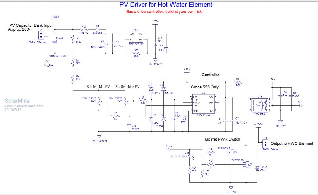 2019-07-12_163950_Circuit.zip |
||||
plover Guru Joined: 18/04/2013 Location: AustraliaPosts: 302 |
I am a bit lost, will assume it is my lack of understanding of the solar cell behavior. The input to the circuit, the approx 260 V is used to set the min 4V and max 8V points for the 555 it is here I get lost. the 260V is that not floating "slightly" up and down depending on solar irradiation? OR Is the circuit actually working in a way that it stabilizes the input to approximately 260 V with the shown values. For the pcb: would there be enough room to also replace the potentiometers with say a combination of 3 or 4 selected resistors. For long term use I have from my industrial work time become suspect of such devices. Nice for quickly set up final tuning, but as I was on the receiving end of being called 3 am to come and fix the !@#$ thing I became a convert to fixed resistors. My boss had a laugh, even we had picked mil spec pots. I learnt something the hard way. Again since I do not entirely understand if the pots will be used 'frequently' the fixed resistors may be a dumb idea.  If it already has been explained clearly in previous posts, just tell me so, I have read all the pages over time but forget too easily. |
||||
| Solar Mike Guru Joined: 08/02/2015 Location: New ZealandPosts: 1124 |
Pots typically adjusted once or twice then left, should be reliable, the ones specified are completely enclosed by a plastic housing, ie safer, because someone will zap themselves setting it up, unless you have a ceramic shaft tipped screwdriver set. once setup by all means replace them with fixed values. The switch voltage points are set by the 555, 1/3 and 2/3 supply voltage, adjust the pots to set correct resistance ratio to suit whatever PV mppt voltage you are using. Upper limit trips mosfets on, dumping element across the 10,000uf cap bank, lower limit turns them off at some lower discharge voltage; enabling a recharge and cycle repeats; pumping high current pulses into the element. Note this is a "poor mans" mppt, the correct set points are for one mppt setting, in reality this setting varies around with temperature and sunlight level, so it doesn't track. The other version I'm building does track and so will be a true mppt, but needs cpu etc so is more complex. No I don't know if a true mppt would be much better and worth the added complexity..possibly not. Mike |
||||
| Warpspeed Guru Joined: 09/08/2007 Location: AustraliaPosts: 4406 |
|
||||
| Solar Mike Guru Joined: 08/02/2015 Location: New ZealandPosts: 1124 |
OK, will allow room on the pcb for a pot with extended plastic shaft, and some extra holes to insert a couple of fixed resistors. Any more ideas.... Cheers Mike |
||||
| Warpspeed Guru Joined: 09/08/2007 Location: AustraliaPosts: 4406 |
You have it all covered Mike. Cheers, �Tony. |
||||
| isochronic Guru Joined: 21/01/2012 Location: AustraliaPosts: 689 |
Weller soldering irons used to use this - a special alloy would become non-magnetic fairly suddenly above a specific temperature (Curie effect) and thereby control the heating / switching. Very reliable, I still have one but the element burnt out - I chased down a replacement element but it was not the aus version ...yada.. anyway... I think now they use inductive heating somehow based on the same principle. |
||||
| LadyN Guru Joined: 26/01/2019 Location: United StatesPosts: 408 |
Thank you! Is the Curie effect self restoring? If the magnet loses its magnetism pass the Curie point, does it automatically regain its magnetism once its back below the Curie point? |
||||
| Solar Mike Guru Joined: 08/02/2015 Location: New ZealandPosts: 1124 |
Logically it must do, otherwise the soldering iron would stop working. I have one of those Weller irons that utilize this effect for temperature control, > 30 years old, still working fine. Mike |
||||
| isochronic Guru Joined: 21/01/2012 Location: AustraliaPosts: 689 |
From memory it is the alloy magnetivity that cycles, not the magnet itself. ie the special alloy blob is in contact with the tip metal, when the blob is cold it is attracted to a magnet and switches the heating on, when it heats up it is not attracted and a spring moves it and switches the heating off. Kind of weird, the entire blob switches practically all-at-once even though there is a temperature gradient across it. Iron, steel, nickel etc all show the effect but from memory they usually have to be way hot before it kicks in. There is a rare metal called gadolinium that switches just above room temp, but it is excruciatingly expensive |
||||
| LadyN Guru Joined: 26/01/2019 Location: United StatesPosts: 408 |
Sounds so much more complicated than a cheap temp. sensor and a comparator. Although, I wonder if the cheap temp. sensor and comparator solution would last decades like this setup does. Truly fascinating. Why don't they teach these here at school? some nice experiments and fun we can have |
||||
