Notice. New forum software under development. It's going to miss a few functions and look a bit ugly for a while, but I'm working on it full time now as the old forum was too unstable. Couple days, all good. If you notice any issues, please contact me.
Warpspeed Guru Joined: 09/08/2007 Location: AustraliaPosts: 4406
Posted: 12:59am 02 Jul 2019
Copy link to clipboard
Print this post
Sounds like you are well on your way with this Dave.
Another simple method to get the required regulated 12v would be to tap some dc from the lowest 24v solar panel, and use an LM317HV high voltage three terminal regulator, as I did in the above prototype circuit. There is very little power involved. It just needs a third wire coming down from the solar array.
I did some solar panel testing about four years ago when everyone was talking about the absolute necessity of having an mppt perturb and observe software algorithm.
So I decided to look at the whole problem myself, and was really surprised to find how little the power actually falls away over a usefully wide voltage operating range.
Its not as critical as a great many people think. What is critical, is limiting the loading to stay within that optimum voltage range, and the loading changes hugely between a dull grey sky, and a clear blue sky.
Constant voltage is a lot easier to do than chasing the power peak around with tracking mppt. And its instantaneous in operation, a lot simpler, and trouble free.
At the time nobody believed me, but you hear less and less these days about do it yourself mppt algorithms, as the real situation becomes more widely understood.
Cheers, ĀTony.
Solar Mike Guru Joined: 08/02/2015 Location: New ZealandPosts: 1129
Posted: 05:26am 02 Jul 2019
Copy link to clipboard
Print this post
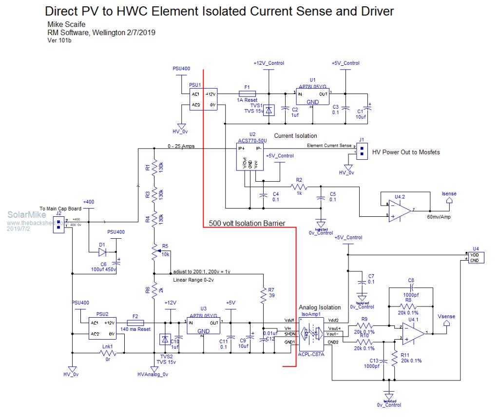
Quite a discussion going on there around the ultra simple circuit; unfortunately the version I'm building has to be semi-commercial in that its going into three sites, one being a community business. So the design has to be idiot proof safe and meet certain standards, any of the parts that users can play with have to be isolated from the 300-400 volts high voltage pv array; I also want it self adjusting to adapt to whatever panels are used without adjustment.
Isolation makes design slightly more complex, current is no problem with a standard sensor chip; analog voltage bit tricky, have used a linear isolation amp here, they have a 2 volt input range 0.5 to 1% linearity.
Proposed isolation stage shown here:
Cheers Mike
johnmc Senior Member Joined: 21/01/2011 Location: AustraliaPosts: 282
Posted: 06:05am 02 Jul 2019
Copy link to clipboard
Print this post
Thanks Warpspeed for your (as always) explanation and very interesting description.
cheers johnjohnmc
Davo99 Guru Joined: 03/06/2019 Location: AustraliaPosts: 1578
Posted: 06:41am 02 Jul 2019
Copy link to clipboard
Print this post
So I take it you are building it for them Mike?
Solar Mike Guru Joined: 08/02/2015 Location: New ZealandPosts: 1129
Posted: 06:52am 02 Jul 2019
Copy link to clipboard
Print this post
See how the prototype performs first, which will go into the house that I'm renovating, I thought it would make a good test site as there is room to put up some panels over the outdoor deck, saves me having to cover it in a roof for shade etc.
Should really get the mppt controllers completed first....
Cheers Mike
Warpspeed Guru Joined: 09/08/2007 Location: AustraliaPosts: 4406
Posted: 10:24am 03 Jul 2019
Copy link to clipboard
Print this post
I don't think there is any doubt about it working.
It seems to be happiest when its very heavily loaded with a short discharge time.
If the heating element is relatively low wattage, then the discharge time becomes very long. It may not even be able to reach the low voltage threshold if the system is overpowered with solar.
That probably does not matter as far as power transfer goes, but it would mean that the heating element is being continuously driven with dc. The thermostat contacts may not appreciate that situation.
Another possible way around the arcing thermostat problem, might be to fit an external temperature controller with its own relay or heavy contactor (or a solid state relay). That could be set to open a few degrees below the thermostat in the heater.
I think the basic concept is quite sound, but we may need to experiment a bit more to get the most out of it.Cheers, ĀTony.
Davo99 Guru Joined: 03/06/2019 Location: AustraliaPosts: 1578
Posted: 12:13pm 03 Jul 2019
Copy link to clipboard
Print this post
To me, That would be a good thing. It would mean the load was getting maximum power. That's not really the point of having this controller though. It's easy to setup for a fixed point like midday in clear weather, it's the hours before 10 and after 2 and cloudy weather is where this will come into it's own and be a huge benefit.
One of the reasons I bought those little power supply's was with the thought of powering an SSR for such a purpose.I have a DC SSR also sitting on my desk in front of me ( with a few other electronic components) but I have read conflicting reports on the things as to their durability.
With my 8 panel test array I experimented with DC switching using normal DPDT relays. I found that instead of switching off, if one gave the power another place to go on the other "resting" contacts, the arcing was no problem at all and due to the speed of the contacts, was no more than what one would expect to see with a heavy AC load.
I found that with the testing I did at around 320V and 500W+, a load around half the primary load was fine at switch to and quenched the DC arc with no problem and could be will less though 50% was completely safe. I would expect a lower dummy load could be used with lower voltages as that seems to be more the problem than amps. As long as the wiring and relay was suitably rated, I can't see any problem with dead shorting the 2nd contacts as that will drop the panel voltage a ton being the problem we are trying to solve here.
Reconfiguring some solar panels today, I was getting 330V@ 1.6A dead shorted. Even at that I could pull some good and lasting arcs. Seems the voltage is more concern that the amps with DC switching.
The way I handle switching with DC is to use the normal switch ( or thermostat) to drive a separate circuit that handles said switching instead. This can be a mechanical relay, an SSR or a mosfet but the idea is to use the thermo just as a switch with no more than an amp @ 12V or less supplied externally on it effectively giving he thing no load at all.
I'll see if I can remember to test the DC SSR tomorrow. I'm interested to see what it can handle and hot hot the thing gets as I have read they are supposed to be heat sunk. I can splice it into one of my arrays that does about 180V @ 10A on a sunny day and see how it goes. The relays I have are only rated to 220V which is a bummer and typical for anything DC, it's all relatively low voltage compared to what one would run solar arrays to. Not sure if a bleed resistor is also needed to turn these things off.
Being a very hands on and put it to the test type, I'm keen to test and experiment and have more panels than any sane on grid person should have.
One thing I tested today after reading your mention of it ( indirectly) was to connect a LED downlight that runs from a small transformer to a DC output from my panels. I made up a cord with a normal AC Female plug at one end and DC connectors at the other. Plugged it into the 4 panel array and the thing lit up like normal. It was overcast and getting later in the day and the thing would kick in with 3 panels in series ( around 90- 105V unloaded) but not 2. I also put on a 5th panel and it seemed to be a bit brighter.
I haven't done much with DC powering things other than resistive loads so this was interesting to me. I might give some battery chargers a go but I'm a little hesitant with the the intelligent type battery chargers for power tools etc just yet.
Is it just electronic/ Switch mode power supply's that will work on DC or will ( against my thoughts) normal wound transformers work too... which I thought needed AC to set up the fields required.
Solar Mike Guru Joined: 08/02/2015 Location: New ZealandPosts: 1129
Posted: 12:28pm 03 Jul 2019
Copy link to clipboard
Print this post
I just looked at the self resetting thermostat that came with the optional 2nd 3KW element I purchased for the testing, its rated at 30 amps/240vac, this gives some margin for boosting the current somewhat, either by using a higher wattage element or increasing the PV voltage above the rating for the element to create higher current pulses, this means the discharge time will have a smaller duty cycle, allowing a longer off period (being re-charged) to help provide arc suppression should the thermostat open.
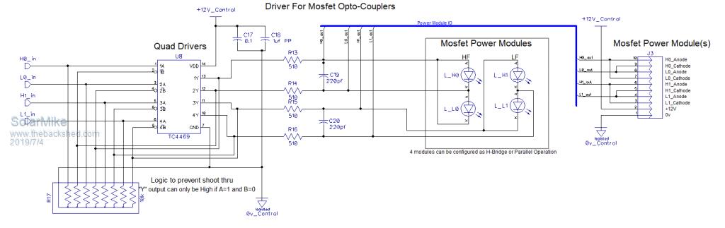
I have always wanted to build a H-Bridge switch for the element so its polarity can be swapped, sort of square wave AC, so will design for that as an option, by using 4 of those power modules. This will also help prevent arc formation as the polarity will switch, having a largeish dead time at the reversal point, don't know how this idea will work until its built...
Cheers Mike
Solar Mike Guru Joined: 08/02/2015 Location: New ZealandPosts: 1129
Posted: 12:41pm 03 Jul 2019
Copy link to clipboard
Print this post
Pretty sure Aussie electrical regs are same as NZ, I wouldn't do that its not allowed in the regs and would compromise any insurance policy should an issue occur like a fire or exploding HWC. The element power must run directly through the thermostat and its safety cutoff.
Cheers Mike
LadyN Guru Joined: 26/01/2019 Location: United StatesPosts: 408
Posted: 06:03pm 03 Jul 2019
Copy link to clipboard
Print this post
Yes, two of those IR2113 could be used or we can steal Tony's MOSFET driver design from the Warpverter to build the H-Bridge.
I will be building the back-to-back MOSFET switch aka the TbsSSR soon and send that to Davo99 for his SSR needs. The challenge is he wants something ready to build and the TbsSSR is just an idea ATM so I have to think about that.
We will build our own. The TbsSSR
I love PV Direct. Been running most of the house off it.
DC switching power supplies will work just fine. Exceptions are input stages that expect sine wave input like boost PFC.
I have been doing this for a few months now and Ben has been having fun with this idea too.
My brothers cannot run their XBOX PSU, dad's CPAP machine also does not work and my inhaler and laptop adapters all fail to run off direct DC because all of these are boost PFC input stages.
Transformers will only heat up at best and burn out at worst on PV Direct because it's a short across a power source and the energy needs to dissipate somehow.
Warpspeed Guru Joined: 09/08/2007 Location: AustraliaPosts: 4406
Posted: 08:56pm 03 Jul 2019
Copy link to clipboard
Print this post
The problem with high voltage dc will always be plugs and sockets and any mechanical switching. All will very destructively arc over, when the circuit is broken under load.
Mike is right about making radical changes inside existing equipment, its much better if we can just connect out magic solar control box between solar and the load (whatever that is) without having to do anything else.
I have no proof or evidence, but believe that if this type of controller continues to cycle, even when at full maximum power transfer, arcing will not be a problem as long as the discharge period is kept short enough to be in the tens of milliseconds range.
That can be done by using a high wattage element that might be rated at about twice the maximum power we plan to transfer. If the duty cycle is then about 50% with roughly equal on and off times, and the discharge time kept short, arcing should not be any worse than with ac.
The discharge time will be the same at all power levels, its the charging up time that is the really big useful variable.
A full bridge dc chopper running at 50/60Hz may be the only workable solution at very high power. But something a lot less ambitious, and a lot less complicated, should be entirely practical.
That is where the circuit designs diverge between building say a low power low cost hobby system to heat a thick concrete slab under a dog kennel might be one fun application.
At the other more serious end of the spectrum, might be for a properly designed very high high power software driven commercial product.
Edited by Warpspeed 2019-07-05Cheers, ĀTony.
LadyN Guru Joined: 26/01/2019 Location: United StatesPosts: 408
Posted: 10:56pm 03 Jul 2019
Copy link to clipboard
Print this post
Here in the U.S., water heater elements available at retail stores have an upper limit.
I think thats 2.5kW for 120V elements and 5.5kW for 240V elements.
I really find the h-bridge based solution intuitive and fool proof
A h-bridge based solution suits this need well, does it not?
The installer/user won't have to worry about what the duty cycles would be with the load and power available. It works regardless
What are your thoughts?
Solar Mike Guru Joined: 08/02/2015 Location: New ZealandPosts: 1129
Posted: 11:54pm 03 Jul 2019
Copy link to clipboard
Print this post
An H-Bridge solution is 4 x more complex, and has higher losses than the simple voltage based switching mosfet. The extra complexity may not be worth it for lower power; until the idea is tested on a live HWC its all theory.
The actual switching arrangement is simpler than that used for inverters as its much slower, I wasn't intending to use any fast PWM here, just alternate the dc polarity on the element every 50hz or so and switch the capacitor across the element when it charges up, hopefully at a faster rate than the polarity switching and will allow higher dc power.
Part of the driver here:
The power module a few posts back already has on it an isolated DC supply and an opto mosfet driver, so four would be required + the above circuit to make it work. The quad driver chip being used TC4469 has four 1.2A cmos drivers on it each with dual inputs, so can be arranged to prevent two outputs becoming high at the same time, over kill for driving 10-15ma into an Led, but its all on one ic so more convenient.
Cheers Mike Edited by Solar Mike 2019-07-05
Warpspeed Guru Joined: 09/08/2007 Location: AustraliaPosts: 4406
Posted: 12:54am 04 Jul 2019
Copy link to clipboard
Print this post
A constant frequency, constant duty cycle low frequency dc chopper could get its gate drive from a transformer with four secondary windings. Cheers, ĀTony.
Davo99 Guru Joined: 03/06/2019 Location: AustraliaPosts: 1578
Posted: 01:41am 04 Jul 2019
Copy link to clipboard
Print this post
Davo99 Guru Joined: 03/06/2019 Location: AustraliaPosts: 1578
Posted: 01:58am 04 Jul 2019
Copy link to clipboard
Print this post
Looking forward to it.
Can I deduce from this that an appliance will simply not work rather than be damaged or is there a risk of damage as well if the appliance is unsuitable?
I would have little idea looking at something what it's internal setup would be. If it's a matter of plug it in and the worst can happen is it won't work, that would be sweet. Could it be that risk free?
Is there a Typical Minimum voltage for the DC to make things run? Even though the LED transformer I tested yesterday had a far lower voltage output than what i was feeding it, took a few panels to kick in.
I suppose with so many things now having a 110-240v input, running half our mains Voltage which would be above 110 would work anyway.
Davo99 Guru Joined: 03/06/2019 Location: AustraliaPosts: 1578
Posted: 02:15am 04 Jul 2019
Copy link to clipboard
Print this post
4800W elements are a standard rating and easy to come by so would allow over 2 Kw which would be quite practical. 2 Kw would reduce the power consumption of a HWS in winter and completely power it in summer.
Most of the designs out there for DC water heating seem to be bit of a joke. I'm reading of 300W heaters which aren't going to do much more than heat up enough water for washing up or a 2 Min shower. 2 Kw is where things start getting practical for a family.
I think I have about given up on solar for any sort or winter space heating especially. The low radiation and the high amount of cloudy days we have had this last couple of months has killed it. I have enough 250W panels to cover my considerable roof area now but it won't meet my winter electrical needs. The electrical heating load has to be replaced with something else.
For winter heating I'm going to concentrate on a waste oil power and combine that with an IMAG generator to make up the solar shortfall. For the oil burners the trick is control and I may be able to hack something up with an arduino to that end.
Solar Mike Guru Joined: 08/02/2015 Location: New ZealandPosts: 1129
Posted: 12:48am 06 Jul 2019
Copy link to clipboard
Print this post
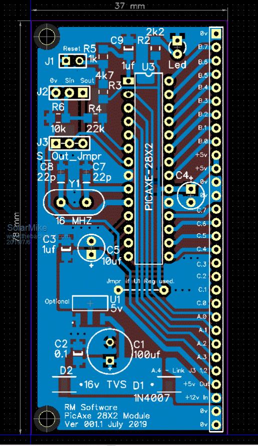
Have decided to use a PicAxe 28X2 cpu for testing this design, it has extra timers and interrupts along with the 64 MHZ speed, so should be fast enough. Once the circuit is working then a Arduino or similar could be substituted.
I also require a cpu for testing the MPPT controller, so have made a generic cpu board for this chip with board connections along one side, so it can be plugged into a 30pin header socket.
If anyone wants to make this generic CPU board, PM me and I will send you the Gerbers.
Cheers Mike.
LadyN Guru Joined: 26/01/2019 Location: United StatesPosts: 408
Posted: 07:05pm 09 Jul 2019
Copy link to clipboard
Print this post
I don't know and I wonder myself, so throwing the question to the far more experienced out there.
My basic understanding is that transformer based PSUs WILL be damaged if run on DC.
limiting current could reduce the extent of the damage.
Boost PFC based PSUs will just not start up. Depending on how the PFC is designed, it will either draw idle power or, over time, be damaged if inductors are switched in the loop while DC is in effect. I would love to learn more.
I would love to know that too. Right now, I have an extra cable running through the house carrying 120V DC and I have marked anything that I know works on DC with a green tab.
This is getting complicated. I would rather plug all the PSUs into this cable and not worry about which one could get damaged on DC.
This is obviously a stop gap until I have a real inverter running.
The Minimum voltage is whatever activates the PSU. Tony has found a few stamp sized 3W PSUs that start up right down to 40v (or so I think).
I just run everything off 110+V DC.
BTW - PV is perfect for heating!
Don't underestimate the insolation on a cloudy day. Silicon PV arrays don't care about infrared as much as you think it does. Infact, they reduce the efficiency due to heating up.
That is why we cool electronic components like our laptops and computers.
Harnessing thermal energy is not what Silicon PV arrays do. Instead they work off wavelengths that help them jump the bandgap of 1.1 eV
My best powerpoint days are cloudy days when the weather is cool.
Start building this project and you will not regret it! The magic is in the caps + control program
Warpspeed Guru Joined: 09/08/2007 Location: AustraliaPosts: 4406
Posted: 09:06pm 09 Jul 2019
Copy link to clipboard
Print this post
That also requites some caution.
Something like just a bare dc to dc power supply may very well start up and run at a voltage way below what it is normally specified to run at. But never forget that for any given level of power transfer, the current must increase as the supply voltage decreases.
Now suppose you have something like one of those small postage stamp sized Chinese dc to dc supplies where the output is rated to deliver two or three watts. But you only plan to draw a very few tens of milliamps from it, not several hundreds of milliamps. It should be quite happy running continuously at whatever voltage it will reliably start up, provided the load is absolutely minimal.
Now my battery monitoring system uses a Dell 17 inch LCD display, and I wanted to run it direct from the 100v dc battery voltage. I was curious to discover how low a voltage it required to start up and run. I was astonished to see it start up and run perfectly normally with only 13v dc supply !!! I very quickly disconnected it.
The problem is that it must draw a relatively huge dc input current at only 13v to supply the 35 odd watts (or whatever it is) to run. Switching mosfets, heatsinks, and the wire in the primary of the switching power supply would never have been designed to run continuously at the current levels that would be drawn at only 13v dc input.
While you can partially load a bare open dc to dc power supply, you can do nothing to reduce the loading of an enclosed appliance. So I would be rather cautious about continuously running expensive items of equipment from an ultra low voltage dc supply, even if it initially appears capable of doing so. It may run, but not for very long... Cheers, ĀTony.


 might be one fun application.