
|
|
Forum Index : Microcontroller and PC projects : H743Zi2 Board
| Author | Message | ||||
| matherp Guru Joined: 11/12/2012 Location: United KingdomPosts: 10240 |
Thanks for all your work on this new board. Once someone in the UK has them in stock I'll get one and then I can see if there is anyway to program round this reset issue. I'll also update the manual with link details etc. Certainly looks like there is a difference in ST-LINK V2 and ST-LINK V3 in this area |
||||
| KeepIS Guru Joined: 13/10/2014 Location: AustraliaPosts: 1872 |
Just as a confirmation of that suspected ST-LINK difference. I installed another ZI2 (V2) board into my general muck around / test / development unit. This unit also uses Peters Backpack board as the carrier and interface to a 9" LCD. I loaded it up and had exactly the same result, no reset at power up if the ST-LINK USB port is not connected to the PC. I soldered a 10uf electro to the underside of the Backpack board from Reset to GND and it now powers up perfectly without any USB ST-LINK connection. FYI These are my final link settings: LINK Connects to PIN JP6 OFF PB13 E-NET SB27 OFF PG11 " " SB29 OFF PC5 " " SB30 OFF PG13 " " SB31 OFF PA7 " " SB21 OFF PA11 USB D- SB22 OFF PA12 USB D+ SB23 OFF PA9 USB vBus SB24 OFF PA10 USB ID SB36 OFF PC4 SB52 OFF VBat is from external backup source. SB57 OFF PA1 E-NET SB64 OFF PC1 " " SB72 OFF PA2 " " SB76 OFF PG7 general IO and not connected to USB Over current. SB77 ON PD10 (DEFAULT) PD10 is reserved for USB power on timing. SB15 ON PC9 (99) to CN12 pin 1 SB14 ON PC8 (98) to CN12 pin 2 Hopefully I've got them correct, there may be another link or two required as I've only focused on "every pin" on the inner rows of CN11 and CN12. Obviously the pins on the outer Rows of CN11 / CN12 that are used for LCD (16 bit), Touch and the SD card are also working correctly. I also remember seeing something about PIN PF11 is not to be used as an AD input, only as a digital IO. It appears that there are interactions between some Pins that exclude ADC on other pins depending on links, so what I hinted about PF11 above is likely incorrect, I'll leave further links to Peter to advise us on as defaults may be fine? Edited link settings NANO Inverter: Full download - Only Hex Ver 8.1Ks |
||||
| KeepIS Guru Joined: 13/10/2014 Location: AustraliaPosts: 1872 |
Used the USB keyboard for the first time since my last post and it Looks like the Keyboard has gone back to being very flaky on initialisation. It now appears to be good when the H7 has been running for some length of time (warm) reverts back to working in 1 in 4 powerups when cold. Drop the CPU back to 400MHz (480 MHz V2 Board) and it will work every time. And a first time ever message today: I was using the Keyboard to change a few thing in the code and, Ctrl-C, type edit, change a tiny bit, Press F2 to save and run, worked 3 times then the ERROR: Fail to write to flash Blank screen - no response via console (expected) reload BIN file, set options, load program and all running again  The second thing I've noticed is when doing a GUI calibrate, the calibrate completes but when it would normally go to the prompt and give you the results, it gives a blank screen and locks. Press reset, do calibrate again and it completes correctly. Never had this with the previous four V1 boards, numerous setups from scratch with exactly the same option (except keyboard) and calibrate sequence. Interesting? Look forward to hearing other user experiences. NANO Inverter: Full download - Only Hex Ver 8.1Ks |
||||
| KeepIS Guru Joined: 13/10/2014 Location: AustraliaPosts: 1872 |
Hoping this will be seen by matherp and it's only a minor thing. When doing an Option List, every option but the Keyboard comes back with OPTION in front as shown below: OPTION BAUDRATE 230400 OPTION COLOURCODE ON OPTION DISPLAY 18, 50 OPTION LCDPANEL SSD1963_8_16, LANDSCAPE OPTION TOUCH 56, 123 OPTION FLASHPAGES 2 OPTION SDCARD 110 OPTION LCDPANEL CONSOLE OPTION CONTROLS 300 USBKEYBOARD US, -79 OPTION RTC CALIBRATE 16 I've made a Win application to save the lists or load and set the Option lists for each project. With the click of a button it saves or sets all options. It makes upgrades / testing a breeze with one button options setup. It would be nice to not have to remember to add OPTION before the keyboard setting when saving a new option list, if not, I can live with it. Thanks. NANO Inverter: Full download - Only Hex Ver 8.1Ks |
||||
| matherp Guru Joined: 11/12/2012 Location: United KingdomPosts: 10240 |
I'll fix it when I next do a build. I note you aren't using a card detect pin for the SD. It is much better if you can as it makes the process of testing for card removal/insertion much more efficient. Otherwise the uP has to send a test command to the SDcard every so often to check it is still inserted. |
||||
| KeepIS Guru Joined: 13/10/2014 Location: AustraliaPosts: 1872 |
Thanks, yes it's the new test unit that's in the finishing stages, I'm fitting an external SD card holder as it's physically difficult to use the Backpack mounted unit. Glad you noticed it as I get focused on other things and might have missed that I hadn't included it in the test unit. NANO Inverter: Full download - Only Hex Ver 8.1Ks |
||||
| KeepIS Guru Joined: 13/10/2014 Location: AustraliaPosts: 1872 |
Had another strange error for the second time. A: Had everything setup. B: Typed RUN C: Program runs fine Repeated B and C quite a few times as I set the RTC and adjusted RTC clock calibration. This is a totally different sequence to the first time a similar incident happened. C: Typed AUTORUN ON A: Got nothing on screen B: Ctrl-C no effect (over console connection) NOTE - The program is not running - no reset or power change yet Pressed the physical reset button and got a screen full of confetti. Then End. Reload BIN Press Reset Blank screen (expected) Load Options, Calibrate and set RTC. Typed Autorun on, press reset and it works perfectly as it has done the previous dozen times. The first time this happened (on a DIFFERENT V2 Board) after setting Autorun on, the screen stayed blank and nothing but a reload of the BIN file would get any life out of board, LCD or console connection. This is not a complaint about anything, just something I've seen twice when "autorun on" was entered, as I never had this on the V1 boards I'm wondering if it's just something about the V2 boards or clock speed, or just random murphy crap. FYI Power is via a dual channel tacking 3A Linear supply when it's on the bench. In the field they have internal 3A switching supplies rated 6V to 40V input fed by 12V 2A plug packs. NANO Inverter: Full download - Only Hex Ver 8.1Ks |
||||
| KeepIS Guru Joined: 13/10/2014 Location: AustraliaPosts: 1872 |
FYI: More on GUI CALIBRATE not finishing sometimes, well it does calibrate, but it does not display any information until CTRL-C is sent, then it pops out the results, I waited a minute for something to show on the console or screen before sending Ctrl-C. There are other commands that don't return to the Prompt and also need Ctrl-C to get a Prompt before the next option can be entered. I don't remember if this was always the case, again it's not a problem, just something I've noticed recently. BTW I have been working with the Board all day and entered FONT 2 again, because the dam thing always reverts to a big font on restart (no program running) and it does not take any notice of OPTION LCDPANEL CONSOLE 2 after a restart, Option LIST only returns "OPTION LCDPANEL CONSOLE" so I've just got used to entering FONT 2 before using the editor or when things get chopped off horizontally. However entering FONT 2 this time caused a blank screen: Here it comes! I pressed the physical reset button and got a screen full of confetti - again. Reload BIN and you know the rest. At least now I only have to press one button and all the options are reloaded and I'm ready to go again. NANO Inverter: Full download - Only Hex Ver 8.1Ks |
||||
| matherp Guru Joined: 11/12/2012 Location: United KingdomPosts: 10240 |
Sorry - getting a bit confused. Are all the issues on the V2 Nucleo? Is everything working as expected on the V1? Are you running the V2 at 400 or 480?. Doesn't look like I will get a V2 until September based on latest delivery estimates. |
||||
| KeepIS Guru Joined: 13/10/2014 Location: AustraliaPosts: 1872 |
Firstly, sorry for not being clear but all Testing is on the ZI2 (V2) boards. I though I'd give an update to ease any concerns about the BIN file or some strange incompatibility. I got hold of a ZI (V1) board and tried the same tests, it worked for a few commands then did exactly the same thing, locked up, then a screen full of confetti after a reset or power off/on. I've spent the last 2 hours trying to pin this down and finally by process of elimination realised that I must have a faulty USB port on the hub. I swapped out the HUB and no more lockups or screen confetti. NO it's not the USB cable - it follows the HUB and the one port on the HUB. I guessing that it's somehow corrupting the data and causing board to crash, but with the USB error checking I'm not so sure of that? But it is what it is. So after getting that major headache sorted, I switched back to the ZI2 (V2 board) and it occasionally will not respond with a Prompt after an option is entered, I remember you saying that the more codepages (memory) we use the slower the Options changes/saves will be? That may account for some of the behaviour? but the (V1) board has not shown this behaviour with the same codepages. It's getting late, but when I get a chance I'll try the ZI2 (V2 board) at 400MHz with all option commands and see If that changes it. One point though, the First V2 board on the running CNC machine died with confetti when a command was entered from the USB keyboard, but it's been running perfectly since then. In any case, the Test ZI2 (V2) board is no longer locking up, so I'm very happy, but Murphy absolutely hates me, I'm sure of it. So Long story short - The only problem left it the occasional "non response" to an option change. EDIT: Oh and the USB keyboard is sort of useless at 480MHz on the ZI2 (V2) you need a manual reset and sometimes have to push it a dozen times to get the keyboard to work, totally random. I've decided to use a tablet via USB for now in the workshop if I need to make a change or test in the machine. NANO Inverter: Full download - Only Hex Ver 8.1Ks |
||||
| matherp Guru Joined: 11/12/2012 Location: United KingdomPosts: 10240 |
Can you check the version of the H743 on the Nucleo. Next to the ST logo on the chip there should be a letter V or Y Can't find a fix for this. Would support for a PS2 keyboard be useful? |
||||
| Bill7300 Senior Member Joined: 05/08/2014 Location: AustraliaPosts: 159 |
I think support for a PS2 keyboard would be generally useful Peter, although I'm unlikely to be able to playing with my H743Zi anytime soon. Bill Bill |
||||
| KeepIS Guru Joined: 13/10/2014 Location: AustraliaPosts: 1872 |
Managed to get photo. 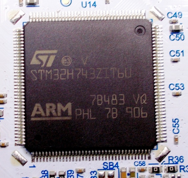 PS2 sockets for case mounting are getting harder to find, and If I'm going to attach something with a lead, then it may as well be a small android or win tablet with a terminal program. I've found when I need to do any field testing or changes, once I get the USB port to initialises, I set CPU back to 400 MHz via the Keyboard and the Keyboard then initialises every time at reset or power up, once changes have been made I set the CPU back to 480 MHz. BTW: The faulty "HUB" USB port causes the V1 board to corrupt almost every time an OPTION command is entered, the V1 board is attached via a separate Console port, don't know if that makes a difference (same Data lines). The V2 board only corrupts occasionally and it's console connection it via the ST-Programmer USB port. This morning, just out of curiosity, I tried various ways to duplicate the corruption and was finally able to reproduce it. This is also likely what happened the first time I got corruption when using the USB keyboard on the CNC V2 (ZI2) controller. If an OPTION command does not respond with a prompt AND I then press Ctrl-C, the memory / program is corrupted. Whatever state MM.Basic is in after the OPTION command does not return "appears" to be causing a corruption when Ctrl-C is used? Interestingly I've only seen this once or twice before as the option command always returns on the V1 boards. Now this is something one would never normally do of course - UNLESS MM.BASIC had appeared to have hung after the OPTION was entered, hence the occasional V2 board corruption issue. Anyway I've wasted enough time on this stupid problem caused mainly by my faulty USB HUB, although it has answered why I had a confetti screen corruption during normal setup on two occasions with the V2 ZI2 boards via the USB Keyboard. NANO Inverter: Full download - Only Hex Ver 8.1Ks |
||||
| KeepIS Guru Joined: 13/10/2014 Location: AustraliaPosts: 1872 |
This is the actual screen copy / paste from my Windows App that automatically sends the options to the micro, and waits for a response from each command. The last command sent is "OPTION USBKEYBOARD US, -79" The response had an extra 9 but whatever. I pressed the GUI TEST Button and checked the LCD. I pressed the GUI CAL button and calibrated the screen. After the last LCD screen circle point was touched there was no result displayed, I waited around 30 seconds before hitting sending a CR and still no result info, I then sent a Ctrl-C and it immediately spat out the response shown. I made sure I waited some time before sending Ctrl-C, just in case the code was still busy doing something? As I found out earlier, sending a Ctrl-C (or pressing Reset) to quickly after an OPTION can sometimes cause code corruption (especially a non-responding option). > > OPTION CPU SPEED 480 Resstart to activate > OPTION RTC CALIBRATE 16 > OPTION FLASHPAGES 2 > OPTION CONTROLS 300 > OPTION DISPLAY 18, 50 > OPTION LCDPANEL SSD1963_8_16, LANDSCAPE > OPTION TOUCH 56, 123 > OPTION LCDPANEL CONSOLE > OPTION COLOURCODE ON > OPTION SDCARD 110, 87 > OPTION USBKEYBOARD US, -79 -799> GUI TEST LCDPANEL > GUI CALIBRATE Done. No errors Deviation X == 7, Y = 3 (pixels) > EDIT: Just duplicated a lockup when setting "Option Baudrate", I had no response, pressed reset and got the Option command still on screen in purple. Power off and on and nothing but the Last Option Baudrate command in purple, obviously no coms at ANY baud rate. Load BIN, send options and set option baudrate, this time I get a response to the command and everything works after reset or restart. NOTE: The first option baudrate (no response) was sent at CPU 400 MHz, the second one at CPU 480 MHz. I don't think it's related to higher CPU speed. EDIT 2: FYI: The Command response is "-79" but some milliseconds later followed up with "9>" which displays as -799> NANO Inverter: Full download - Only Hex Ver 8.1Ks |
||||
| ceptimus Senior Member Joined: 05/07/2019 Location: United KingdomPosts: 130 |
I got one from Digi-Key in the USA. Free shipping to UK if you spend over �30 - I added a pair of wire strippers to my order to take it over the limit, which meant I got the wire strippers for free: without them the total cost including shipping would have been the same. Digi-Key guarantee to pay any customs charges and the board arrived within about three days of ordering. Numbers on the board/label: NUCLEO-H743ZI2 NUH743ZI$AT1 MB1364C 1902 I just programmed your latest 5.05.09 (before that I had 5.05.05) and the only connection is to the PC USB to power it and communicate via Tera Term. I have your 5.05.05 manual but many of the SB links mentioned there aren't present, as far as I can see, on my board the highest numbered one is SB82 on the back. At the moment I've not changed or removed any links or jumpers. Is there a schematic or table somewhere showing how to connect an SD card and ILI9341 16-bit? I'm a newbie to the H7 but I'm happy to run any tests I can to help. |
||||
| matherp Guru Joined: 11/12/2012 Location: United KingdomPosts: 10240 |
The intention in removing links is to ensure that any on-board devices on the Nucleo are not compromising pin usage for MMBasic. In particular there are a lot of connections to the ether-net port that could impact. You will need to go through the Nucleo manual to identify those that should be removed. Please post what you find or alternatively it may be that KeepIS has done the analysis? In addition there is a link that connect 3.3V to VBAT. If you want to use an external battery to keep the RTC running that link needs to be removed. All mandatory connections for the SDcard and ILI9341 are given in the section of the manual on "144-pin Test and Development Board" - page 6 in my version. Pins marked "configurable" can be allocated at your discretion. Note I just posted a very minor update to the firmware here |
||||
| KeepIS Guru Joined: 13/10/2014 Location: AustraliaPosts: 1872 |
matherp posted a link to the V2 circuit on the 1st page in this thread. I went through the H7 MMBasic manual and posted the final links I set for the Z2 towards the top of page 2, everything works with all my programs initially written for the Z1. I use almost every I/O pin on the Z1 and Z2, 7" LCD, SD card, USB, H7 Backpack etc. NANO Inverter: Full download - Only Hex Ver 8.1Ks |
||||
| Tinine Guru Joined: 30/03/2016 Location: United KingdomPosts: 1646 |
Considering switching to the H7 and have just ordered one. So, bottom line....is this device as rock-solid as the Explores? I realise that there is greater speed/memory but are there any negatives compared to the Explores? |
||||
| KeepIS Guru Joined: 13/10/2014 Location: AustraliaPosts: 1872 |
I used the Explorer for years and switched to the H7 when one complex programs would no longer fit in the Explorer memory and I ran out of I/o ports on the E100+. H7 hardware has been 100% rock solid, on both the V1 and now using the V2 H7. The fab port by matherp and the extra features he added are just icing on the cake. In my case I haven't found any negatives, only positives. Mike NANO Inverter: Full download - Only Hex Ver 8.1Ks |
||||
| Tinine Guru Joined: 30/03/2016 Location: United KingdomPosts: 1646 |
Thanks Mike. Mine arrives today but I had to leave town for the rest of the week....Grrrr. Showing my Arduino ignorance but does the compatible header mean that we can use Arduino shields, etc? |
||||
| The Back Shed's forum code is written, and hosted, in Australia. | © JAQ Software 2025 |
