
|
|
Forum Index : Solar : Simplified Solar Hot Water
| Author | Message | ||||
| iispip Newbie Joined: 03/12/2019 Location: IrelandPosts: 4 |
Thanks Tony you are right currently in the depts of misery with short dark days. what are these rated for tony? can they be rated for up to 230vdc @ 2000 watts. Does any of ye electronic genius�s have a spare one to sell ? life would be much easier if i was back in the Ozzie sun  |
||||
| iispip Newbie Joined: 03/12/2019 Location: IrelandPosts: 4 |
The one you have made and not tested Tony can you put up some clear pictures of it if possible  thanks iispip |
||||
| Warpspeed Guru Joined: 09/08/2007 Location: AustraliaPosts: 4406 |
The basic idea is that you build whatever you need. Decide what voltage and power the heating element is, and how many solar panels you are going to need to power it. Then you build your control system to suit. Determine your maximum power voltage and your switching points from the rating sticker on the solar panels. And the equip it with suitably rated mosfets and sufficiently large heat sink. I never actually built one and have no need, as all my hot water comes from very low cost natural gas. I did this as a service for other Forum members. Its a perfectly sound design and will definitely work. Cheers, �Tony. |
||||
| tytower Newbie Joined: 19/11/2017 Location: AustraliaPosts: 21 |
Ill start a new thread on this . Just wondered if you have seen the Youtube videos of a guy called "Opera"? Hes heating hot water direct from solar panels he claims but I have tried following what he's doing and he has made it very confusing. Changing inverter boards and supercaps, out of focus and poor lighting etc. Ive got one going to the point of getting a voltage out of the board but its damn hard to work out where to connect the ins and outs . So anyway I'll start another thread and hope you guys will jump in there too . Thanks. 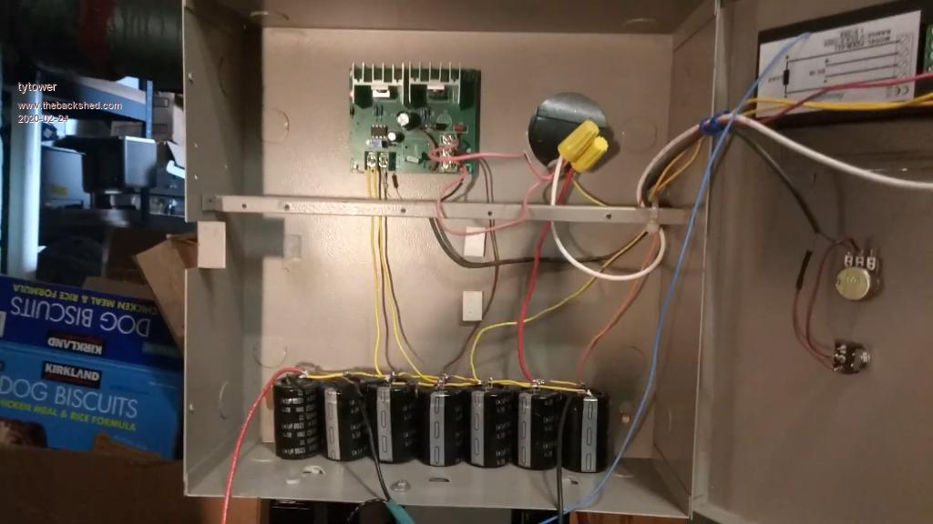 Edited 2020-02-25 08:24 by tytower |
||||
| Davo99 Guru Joined: 03/06/2019 Location: AustraliaPosts: 1577 |
I have been working on something similar for many months and finally cracked it. Rather than using inverter boards, I have used a a Battery charger board and a voltage level switch. They are both 12V but I will use them to regulate an array of panels that will go to about 260V and run on a normal 240V element. I'm using a voltage Divider to get the voltage from the panels down to something the board can handle and measure. The panels will charge a bank of caps to their open circuit voltage and then once they reach that, the board reads the voltage and triggers an SSR. The Caps Discharge into the element and the board resets and repeats the process. The boards have mechanical relays which are bypassed and the output taken straight to the SSR which require less power than the mechanical relays. The voltage switch boards have an upper and lower limit. I don't think the lower limit will be needed as it will climb fast just on the caps and I don't know if the board could cut fast enough anyway. As warp worked out, 10% off power point does not make a lot of difference to the panels and as the load from the caps is minimal during charging, they seem to come up very fast and the cycling is also. In testing with a 100W Bulb as a load and just one cap and panel late in the afternoon, I could not get any illumination from the bulb at all, not even the faintest glow. Even with the mechanical relay doing the switching (which is very slow in comparison to a solid state device which could also just be a mosfet or series thereof,) The bulb lit quite well. A very graphic illustration of the benefits of having the panels in their happy place. Before this I experimented with just a PWM controller. This was also enlightening ( pardon the pun) as even with this, it was evident much more power could be gained over the course of a day throttling the load at a fixed rate than just having the panels directly connected which was hopeless. The vids opera made no sense to me but reading here I got the idea of what needed to be done and worked out what I could use to achieve it. I imagine the efficiency is still Horrible compared to what the smart people here have built but I'm happy I was able to work this out and it's a LOT better than nothing at all that's for sure. From here I just need to work out what are the most common and easy to get boards as well as the cheapest that will do the job so I can do some step by step how to Videos and standardise the procedure for others to follow. One thing I may need to do is work out how to measure the highly pulsed output to compare it to direct coupled. |
||||
| Warpspeed Guru Joined: 09/08/2007 Location: AustraliaPosts: 4406 |
Great work there Dave. One fairly simple way you could make some comparative power measurements might be to average out the pulsing voltage across the heating element. That could be done by charging a large electrolytic through a high value resistor. � The electrolytic will try to settle at some average of the on/off voltage that can then be measured directly with a multimeter. It may still be pulsing a bit, but some kind of average heating element voltage can probably be "eyeballed" if the pulsing is not too violent. Power will be proportional to voltage squared, so a little bit more measured voltage will indicate a correspondingly larger increase in actual heating power. Its a bit Mickey Mouse, but it may usefully provide some kind of relative power indication for initially setting up the voltage thresholds and trying out a few different variations. I think you will find that its all not in the least bit critical. If the voltage switching thresholds are moved closer together, that will make it cycle much faster, but the averaged out voltage across the load, and hence the average heating power into the load will not change by very much. Averaged and steady dc measurements will be quite comparable as far as actual power comparisons go. Cycling rate is not going to have any effect on total power transfer of efficiency, so you can build it to cycle as fast or as slowly as you wish, and the final heating results will be the same. The whole thing will always self adjust to match any combination of panels and available solar, to any heating element, so long as the two voltage switching thresholds are suitably set. The way you have cleverly done it by combining simple readily available parts will be just as efficient and effective as some high tech software system on a fancy circuit board doing exactly the same thing. Its a very simple idea that once understood, can be put into practice fairly easily in a variety of ways. Edited 2020-02-26 08:43 by Warpspeed Cheers, �Tony. |
||||
| Davo99 Guru Joined: 03/06/2019 Location: AustraliaPosts: 1577 |
That makes sense. I was thinking of something like charging a cap through a diode and having a drain on the other side like a bulb to measure Current as an indication. Doesen't have to be relevant to anything other than indicating when there is more or less power. Resistor is the same thing and would waste less power. You read my Mind with this Tony. I was wondering about that very thing in reference to the size off the cap bank. Obviously the larger the longer the time to charge but I get the feeling that is going to be fractions of a second for the most part in any useful lightning rather than seconds. The only thing I was concerned about was the ability of the SSR to cycle fast enough But I think that won't be a problem from what I have looked up. On that, I seem to recall reading where I think it was you that suggested on someones real circuit to put in a Diode? to protect the Mosfet? from the back Current ( emf?) when the relay was tripped? Could you advise if you think I should Put some Diodes ( have some 10A's Or 30A Bridges in the box) for that or is it only relative to something else? Also, I have a 25A SSR from memory. I also seem to recall some advise about under rating them. Would you suggest 1 or 2 in parallel for this? I am aiming to drive the element at full voltage if not full amperage from the panels but the caps discharging May give it more of a belt of amps than my limited knowledge understands. Even testing with one panel at around 34V, I'm impressed with the crack they give when charged and shorted with a screwdriver. :0) Would indicate some substantial amps. is there any advantage or disadvantage to either way? Heat in SSR's? That was I thought. This should adapt to any amount of panels as long as the series Voltage was taken into account and duly set. Is having the voltage closest to the elements voltage going to be better than say the same amount of panels in half the series and paralleled? I'm thinking the closer the voltage the better even if the power is the same although paralleling may lead to faster cycling but I'm thinking that's going to be pretty fast in the main anyway. Might be safer for people to run 2 arrays at say 130V than one at 260V is all I'm thinking. Thanks, that is good to know. I want to say that I do appreciate the circuit you made and I will build that but I just had this thing stuck in my mind that there had to be a way of doing it with the boards available off Fleabay and I had a compulsion to work out how to do it. I had in mind it wasn't hard and now the .5V light in my head has flickered I can see it's laughably simple but I have seen this has been something many other people on DIY power and off grid interested types have also wanted to do and been baffled by. I have Bought quite a few different boards and spent hours looking at different ones and ways of doing it but always run into dead ends because of my ignorance of some very fundamental things. I'm very pleased now that I can see the basics of making them work, pretty much all the things I thought had potential can be adapted. Some more simply than others but seems I was on the right track which is a win in my mind. Exactly! I thought that's how it would be but as I have found with many things I have put my hand to in the past, the most basic parts of a technology are often the most difficult to grasp. I think because the most fundamental things are assumed and not many people mention them. Of course once you get the first bit with the understanding of the concept, it's easier to build on your Knowledge from there. |
||||
| Warpspeed Guru Joined: 09/08/2007 Location: AustraliaPosts: 4406 |
A diode will charge the cap very quickly up to the peak voltage, which is not what we are trying to measure. A resistor will charge the cap when the heating element voltage is on, and discharge when the heating element is off.�The resulting voltage on the cap will give a time averaging effect which is what we want for measuring the average power. Try and dig up a specification for turn on time, and turn off time for the solid state relay. Some can be fairly slow. But a cycling on and off at a hundred times a second might be o/k, but check. There is no real advantage with adding capacitors and slowing it right down. So its a bit of a compromise. Fast is good as long as your switch can handle the speed. �If its getting unexpectedly hot, try slowing the whole thing down a bit by spreading the voltage trip points or adding more capacitors. A diode will be necessary across the heating element, and some kind of transient suppression across the switching device, a commercial solid state relay should already have that inside. It should normally discharge through the heating element, and the current will be limited by that. But you are right, stored energy can do mighty things ! Very slow (several seconds per cycle) might have some definite advantages for a motor load, but for heating it does not really matter. A solid state relay will be relatively slow because the gate of the internal mosfet is only powered by a few miserable photons. One or more decent mosfets on a heatsink driven directly will be much faster. Thousands �of cycles per second would be practical and easy. Yes its better to match the voltage at flat out full summer power. Ideally at a higher overall voltage. Less current means lower switching losses and less heat to get rid of in the heatsink. But you can stretch that concept out a fair bit and still get excellent results. Now take a completely silly extreme example'  ' Suppose we have eight 250 watt 30v panels, giving us about 2Kw at 240v dc. �And we have a 24v 2Kw heating element (24v 83 amps). ' Suppose we have eight 250 watt 30v panels, giving us about 2Kw at 240v dc. �And we have a 24v 2Kw heating element (24v 83 amps).Our capacitor charges up, and the solid state relay cops 830 amps of discharge. Quite possible, and it would work in theory, but its a pretty hard hit for both a solid state rely and the capacitor. But a 2Kw 240v heating element might discharge at only 8.3 amps under identical conditions, and whatever switches the power is going to have a much easier life. A 120v element might average out at 33.2 amps discharge, still perfectly practical. But a 24v element with 240 v of panels would be totally over the top. So its better to get something fairly close, but the match does not have to be exact. Yup ! � Once the idea catches on and a few different people have built working systems, I think this is going to become quite a popular thing. That is what intrigued me most, even though right now I do not plan to build one myself. Its very easy to over complicate things, but the concept of sweeping the panel voltage back and forth through the "sweet spot" of maximum power without overloading the panels in awful cloudy weather works better than I had dared to hope. Exactly! I thought that's how it would be but as I have found with many things I have put my hand to in the past, the most basic parts of a technology are often the most difficult to grasp. I think because the most fundamental things are assumed and not many people mention them. �Of course once you get the first bit with the understanding of the concept, it's easier to build on your Knowledge from there. Too true  Edited 2020-02-26 18:21 by Warpspeed Cheers, �Tony. |
||||
| Davo99 Guru Joined: 03/06/2019 Location: AustraliaPosts: 1577 |
Thank you again Tony for all the very helpful Information. It is appreciated. |
||||
| Warpspeed Guru Joined: 09/08/2007 Location: AustraliaPosts: 4406 |
There are probably two fairly obvious contenders for mosfets. FDA50N50 which is 500v 48 amps and rdson 95 milliohms these are available from e-bay for about $15. I have used a lot of these, and are what I currently run in my Warpverter for the two smaller inverters. TK62J60W this is a much more recent device 600v 62 amps and rdson 33 milliohms available from e-bay for around $25. Either would do. I think I would prefer the cheaper device to experiment with initially, and probably the larger one for the final project once any bugs have been sorted out. Its important to connect a transient voltage suppressor right across the mosfet source to drain. A 1.5KE350 (350v) or 1.5KE400 (400v)would be ideal. How much heatsink ? A 3.6Kw element might be carrying roughly 15 amps, and 95 milliohms would be 21 watts for one of the smaller mosfet. The absolute minimum for that might be about a five inch by five inch vertical flat 3mm aluminium plate, and something larger would be advisable. A pair of the smaller mosfets would halve that power and spread the heat better. Instead of 21 watts for a single mosfet, 10.5 total watts would be spread across two mosfets. In other words about five watts per mosfet. That would be far better. The larger devices are much better with 33 milliohms. One mosfet 7.4 watts and a pair only 1.85 watts each. That does start to get expensive though. Its not so much the current carrying capacity as keeping the mosfets cool that will be the main consideration. Cheers, �Tony. |
||||
| Davo99 Guru Joined: 03/06/2019 Location: AustraliaPosts: 1577 |
Thanks again Tony. Could you briefly explain why you suggest those mosfets instead of something like an IRFP460? Nothing to do with the fact I'm cheap ( really!) just Curious. Is it because of simplicity of using 1/2 of those instead of Multiple of the others? Also, can these be nameplate rated in this application or do you suggest say 50% rating or 25% amperage? I looked up the voltage suppressors and have ordered them already. As Far as Cooling the mosfets, I'm a big fan of forced air. Plenty of computer CPU heat sinks with fans in the box. Thinking I can use those little transformers you have recommended and tap off the solar input to run them. I think the computer CPU heat sinks and Fans will handle the heat you suggest quite well. Do the Fets need silicone insulators to prevent the whole Heat sink becoming live? |
||||
| Warpspeed Guru Joined: 09/08/2007 Location: AustraliaPosts: 4406 |
I just had a look at the IRFP450 datasheet. https://pdf1.alldatasheet.com/datasheet-pdf/view/37024/SAMSUNG/IRFP450.html 500v 13 amps, rdson of 400 milliohms, and a maximum power dissipation of 150 watts at 25C junction temperature. Its a truly ancient device, good in its day, but that was a very long time ago. Compare that to an FDA50N50. https://pdf1.alldatasheet.com/datasheet-pdf/view/245763/FAIRCHILD/FDA50N50.html 500v 48 amps, rdson 105 milliohms, and a maximim power dissipation of 625 watts at 25C junction temperature. Time marches on and things get even better. The TK62J60W. https://pdf1.alldatasheet.com/datasheet-pdf/view/469300/TOSHIBA/TK62J60W.html 600v 62 amps, rdson 33 milliohms, and the maximum power dissipation of 400 watts at 25C junction temperature. The FDA has a much bigger chunk of silicon inside, 625 watts of heat dissipation versus 400 watts for the TK62J60W. Its a massive beast of a mosfet. However the TK62J60W is a smaller but higher tech and better performing device overall. The IRFP450 is old and weak, and unless you can get a whole bunch of them for free, not really up to any kind of serious job these days. Its rather like.... You could couple up a hundred chickens to pull your plow, or one horse. Edited 2020-02-27 18:02 by Warpspeed Cheers, �Tony. |
||||
| Warpspeed Guru Joined: 09/08/2007 Location: AustraliaPosts: 4406 |
Further random thoughts on this... If you start out with something like eight 24v 250 watt panels in series, and couple that up to a 230v 2.5Kw (or 3.5Kw) heating element, that would certainly get you started. The controller will then cycle on and off, and the more sun there is, the faster it will cycle. At mid summer, the power from the panels might just be high enough that the solar panel voltage will never drop far enough under load to turn the controller off. We then have the happy circumstance that the panels will be feeding the heating element directly and continuously. If a cloud crosses over the sun, the voltage may fall and it will start to cycle. But it will go back to continuous operation when the cloud passes. Under extreme evil cloud, it should still cycle, but the capacitor may take a very long time to charge up to the upper voltage threshold so it can then dump its energy into the heating element. Cycling will be painfully slow, but it will still be heating by a very small amount. One thing we could do to improve winter performance would be to add more series strings of panels to the system. Suppose we had three series strings, each of eight 250 watt panels connected to our controller, and potentially 6Kw available. In mid summer the 2.5Kw (or 3.5Kw) element is still only going to draw its rated power. But on really gloomy days there will then potentially be three times the power available than having only the one 240v series string. Cheers, �Tony. |
||||
| Davo99 Guru Joined: 03/06/2019 Location: AustraliaPosts: 1577 |
Thanks for the info and thoughts Tony. I had guesses as much as what you said with the panels being a direct connect in good summer sunlight and being slow in lower light. It's the imperfect light where a controller will shine, pardon the pun. I am all over the series parallel idea. All my GTI's are over clocked by at least double with the panel power. You cannot have too many panels in parallel ( as I just came from arguing with someone on another forum that has never done anything hands on in their life clearly but wants to be seen as an expert in everything) and the more you have the better the ramp up, ramp down and performance in crappy weather. As long as the total Voltage with the rated power of the element is not exceeded, you can have 100Kw of panels on an element and it will be fine. Same as a GTI. I was crunching numbers on this last week. I am a bit in 3 minds about panel capacity. If you have enough for the elements rating , on a decent day you will also have no problem getting even a fairly large heater up to speed. I figure where I am, 6 hours of useable light should be workable in winter. Summer of course is not a concern. On crappy days however, I'm not sure any practical amount of panels will do one much good because the fall off is so dramatic. They could help with the in between days however where maybe it's not completely overcast or you have the weather changing through the day where it's crappy at one point and clear at another. I think the practical outcome and amount of panels would be highly dependent on local weather condition's as well. Double probably wouldn't be a bad thing if one had the space. If one had a use for the excess power.... That's something I have been trying to come up with for a couple of years as half my inverters are shut down over summer and I still make too much power. If I could find a practical use for that power..... Maybe I'll buy a spa... heat it with an oil burning gas water heater in winter and use that as thermal storage and pump the water in through a radiator to heat the house in winter and..... I'm going to set up a 50L water heater I got a few weeks back and see how that goes. I'd like to find a way to monitor the temps and power that goes through the thing and connect it as a pre heater for my main HWS over the winter. I'll have to look at the thermometer boards I have and what sort of power meters are available atm. |
||||
| Warpspeed Guru Joined: 09/08/2007 Location: AustraliaPosts: 4406 |
Have to agree. I think one series string pretty well matched to the heater element to get started with, would make a fine beginning. Doubling up on panels later would make a nice upgrade. But beyond that the point of diminishing returns quickly kicks in. On a bloody awful grey day, twice or three times nothing, is still nothing, and adding extra solar panels is going to do zip. Cheers, �Tony. |
||||
| Davo99 Guru Joined: 03/06/2019 Location: AustraliaPosts: 1577 |
I think that's it in a nut shell. I have seen on my inverters that can make 30 Kwh+ one day and barely 3 the next that they are either going to produce or they are not with given conditions. I was just playing with the capacitor bank of 4X 1000 Uf units. It's just after sun set and there is no direct light on the test panel on the roof over my office. My inverter with about 11Kw of panels on it on the same roof is making 25W so it's for all intents and purposes dark as far as panels go. I hooked up the test panel to the cap bank and put a volt meter across it and then shorted the caps with a screwdriver. When I removed the short, the cap bank charged back up in a bit over 2 seconds. I know it was said that the cycling rate didn't matter but is this going to be too fast when there is actual sun on the panels and I'm pumping a couple of KW or more into them? I have seen others here and on the net tend to use many more caps so should I go for 10 instead of 4 or it just won't make any difference at all? Might drag out some panels tomorrow and hook up the water heater and see how it goes with a KW of panels attached. |
||||
| Warpspeed Guru Joined: 09/08/2007 Location: AustraliaPosts: 4406 |
I think you are just going to have to do some testing and see how it goes. Working it out theoretically is possible, but there are a lot of unknowns that must be measured first. Easier just to suck it and see, and make adjustments as necessary. Half a Hz is pretty slow, and a couple of hundred times that cycling speed would not be outrageously fast. If there was 20 watts there, it might go to 100Hz at 4Kw. Not unreasonable. Cheers, �Tony. |
||||
| Davo99 Guru Joined: 03/06/2019 Location: AustraliaPosts: 1577 |
I ordered some Boards last week before I went away. Found some of them in the letterbox this morning. I thought the corona Virus might have made them take months to arrive but maybe the load has lightened and they are getting here faster. Of course the ones I got were all spares for the box I have used on other things recently and the ones I really wanted for this project are still in transit. Have a couple to go on with I can use and maybe with a bit of luck the others or at least some of them will arrive next week. In the mean time I'll go sort through the pile of Dud inverters I have up the back and see if I can pull some more caps. might go visit the solar place dumpster tomorrow and see if there is any treasure waiting for me. Always amazed at the stuff they throw out. Brand new Switches, brackets, tek screws, cable fittings and so it goes. The only thing concerning me at this stage is making sure I get the voltage Dividers right and not blowing the proverbial out of the boards. |
||||
| Davo99 Guru Joined: 03/06/2019 Location: AustraliaPosts: 1577 |
This morning on my web trolling for boards I came across this one: battery charger Board This seems to be a new generation and step up over the existing boards. It uses an LCD readout instead of the LED decimals that look like a throw back from the '80s and the thing seems to have IO ports and mentions data collection. I have ordered a bunch of these for both my solar water heating proclivity and to use as designed. With a 6-60V input, they can easily be coupled direct to a panel and a battery. Used others like this but so far what I have found all needs a voltage converter to work with panels. My father has a bunch of things in his machinery shed with rather expensive float chargers on them. My machine shed has no mains power so these things would be idea. One 190W panel would drive a fair few of these things to float voltage for maintence purposes and the price would be less than a 10th of a lot of these commercial float chargers. I find looking at them the 30A rating to be highly Likley typical complete and utter chinese bullship but not really a concern. There is another similar board that is different and rated to 10A but again, for my purposes even half that will be fine and If I want high power I'll just use the thing to control an SSR. These would also be good for a mains battery charger. Mine is a High power thing but not automated and I have forgotten about it before and boiled batterys with it. I'll put one of these in with the posh looking LCD and not have to worry again. Thought these were very interesting with the LCD and the IO ports as to just how advanced these cheap little boards have become. Looks like LCDs have become cheap enough to put on other things as well now. I do wish they would do away with the mechanical relays and use SSR's or Mosfets though. Make my water heater setup that much easier. Haven't seen any that use a Mosfet so far. I'd think that would be an advantage for reliability and for use in not having a relay clicking all the time. |
||||
| Solar Mike Guru Joined: 08/02/2015 Location: New ZealandPosts: 1125 |
Hi Davo, that's a good find, keep us informed how well it works. You could add a mosfet to the mix, see cct below; use the on board relay to switch a +ve gate voltage to an external mosfet or 2 in parallel. 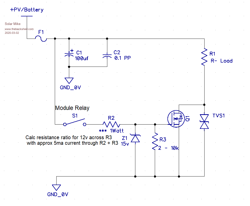 If you need assistance in calculating suitable R2/3 values PM me. Cheers Mike |
||||
