Notice. New forum software under development. It's going to miss a few functions and look a bit ugly for a while, but I'm working on it full time now as the old forum was too unstable. Couple days, all good. If you notice any issues, please contact me.
Davo99 Guru Joined: 03/06/2019 Location: AustraliaPosts: 1577
Posted: 12:08am 04 Mar 2020
Copy link to clipboard
Print this post
Hi Mike,
I may have misunderstood what you are saying with that circuit, but due to the frequency of the switching, I was thinking to eliminate the relay all together.
Can't see it doing the suggested frequency of up to 100hz and I doubt the thing would run much over 10 hz anyway. Of course if it did, I imagine it would wear out pretty quick even if they are rated to 10M cycles as I have read.
My idea was to remove the relay and replace it with a mosfet or an SSR.
I have been looking at different sites and there are a lot of different board that would work all the same way. I'm thinking that an external box could be added that was premade with the voltage divider the cap bank and the SSR already configured. all one would need to do would be connect the wires to the board and tap off the relay drive side contacts. If the relay fell over in time, no problem.
Of course now I have figured this out, I'm thinking of how to do it with an arduino. In looking at that I'm coming back to simple ways to build these from components as everyone here advised in the first place.
I'll get the boards up and running first. Hanging for a delivery of the boards I have ordered. Everything is saying orders from China may be delayed. Got some voltage regulators in a week on Friday,much faster than usual so hoping everything else follows suit.
Wet and overcast here today so I have been playing with PWM controllers. Just driving a H4 globe, the effect of keeping the panels on power point is quite dramatically illustrated. The light levels haven't altered much at all so far today so it has me thinking that a simple PWM controller ajusted a few times a day would even be a vast improvement on direct connection, even if the panels were Ohm matched to the load. Far from perfect but if the overall result is better.... For $10 and connecting 4 wire, definitely worth it.
I have a 90V 20A PWM controller so it would certainly drive a 48V 1500W element to a very decent output and possibly do quite well with a 240V element also.
have to set up some panels and find out! :0)
Warpspeed Guru Joined: 09/08/2007 Location: AustraliaPosts: 4406
Posted: 12:43am 04 Mar 2020
Copy link to clipboard
Print this post
Dave, I plan to order a big bunch of boards (for five different projects) from China in about a weeks time, it appears most of the Chinese are now back at work.
I will include a minimum order of five "Solar Hot Water" boards with that. With combined postage, the extra cost will be minimal.
It will be the exact same circuit as shown at the beginning of this thread, and it will drive two parallel mosfets at any speed.Cheers, ĀTony.
Solar Mike Guru Joined: 08/02/2015 Location: New ZealandPosts: 1125
Posted: 02:29am 04 Mar 2020
Copy link to clipboard
Print this post
Dave,
That generic mosfet circuit was to provide a higher current than the PCB relay could provide, but if you are switching 10-100 HZ or higher rate then the relay has to go, it wont last long. I would take up Warp's offer, it will be a better engineered solution than messing around attempting to Hodge bodge (is that the term) off the shelf modules.
I just got my boards back and ordered a new batch, seems factory is near back to normal.
Cheers Mike
plover Guru Joined: 18/04/2013 Location: AustraliaPosts: 302
Posted: 03:07am 04 Mar 2020
Copy link to clipboard
Print this post
Warpspeed I am curios as to whether you take orders on the boards? I have been looking to see if anybody had made gerbers of your board but struggling even to keep up with reading forum posts, may have missed gerbers being mentioned.
In case you are selling the bare boards I wold be happy to take 2 off you? Edited 2020-03-04 13:08 by plover
Warpspeed Guru Joined: 09/08/2007 Location: AustraliaPosts: 4406
Posted: 03:44am 04 Mar 2020
Copy link to clipboard
Print this post
I only completed the circuit board layout for this yesterday. But now have Gerbers that I can send out for free if anyone wishes to e-mail me.
Has to be e-mail, I cannot attach anything to a PM. Edited 2020-03-04 13:46 by WarpspeedCheers, ĀTony.
Davo99 Guru Joined: 03/06/2019 Location: AustraliaPosts: 1577
Posted: 04:37am 04 Mar 2020
Copy link to clipboard
Print this post
Hi Tony,
That would be great. More than happy to fix you up for the cost of the boards and postage etc. Let me know how much and your bank details and I can do a transfer.
15 Components I know is Tiddly winks but will still probably be a challenge for me to put together.... unless you would like to put one together for testing and for me to work from.
Thank you for your efforts. Very kind and generous of you indeed!
Davo99 Guru Joined: 03/06/2019 Location: AustraliaPosts: 1577
Posted: 04:47am 04 Mar 2020
Copy link to clipboard
Print this post
I certainly will ( have!)
I fully agree with what you say about them being a better solution, no question about it but just the same I will pursue my sh*thackery with the other boards simply to prove to myself that it can be done and to fulfill my idea to completion. I know that doesn't make much sense when there are better solutions but it's been bugging me a long time and something I want to see through.
I would also like to show the setup to others whom like me, may be a lot more competent at attaching wires than they are circuit design and building which to many of us mere mortals, is pure and utter magic performed by wizzards!
The factories being back up to speed is interesting. It's very hard to judge the seriousness of this Corona Virus from the media. Is it a beat up to replace the bushfire headlines, is it being kept quiet to avoid panic and is much worse than we are being told, or....?
The factories going back would seem to indicate the worst has passed in China at least. Hopefully very little comes of it here or anywhere else. With winter coming, it is a concern though.
Davo99 Guru Joined: 03/06/2019 Location: AustraliaPosts: 1577
Posted: 05:10am 04 Mar 2020
Copy link to clipboard
Print this post
Something I was thinking of with this setup of switching the caps in and out with the thermostat on the water heater....
Given that it will be a charge/ Discharge cycle and in effect have a zero point when the caps have dropped their power into the element, will it be possible to use the standard Thermostat or will there still be too much potential arcing and the thermostat would need to drive an SSR to cut the input power to the circuit?
I'm thinking that at full speed, the pulses should be at or greater than mains frequency and even in lower light levels, the charge time on the caps will be slower but the discharge time should not be any different and quite rapid rather than a prolonged event that causes the damage to contacts. It's only the power levels that will take longer to come up, nothing changes on the load side so the discharge should be far faster than 1/50th of a second same as mains zero point would be.... If I am saying that right.
I played around with switching DC before with DPDT relays. I found that the DC power had something akin to Momentum. Once going it didn't want to stop which is what causes the arcing. I found that by using a DPDT relay with 50% or better ( Can do less but 50% seemed reliable) alternative load to divert the power to, the relay switched with no more arcing than one would expect carrying an AC load.
I also found with the power I was using which off the top of my head was about 1.5 KW, That dead shorting the second set of contacts quenched the arc as well. With shorting the panels, as this whole exercise is about, the power levels from the panels drop dramatically so the load on the relay is reduced anyway.
Everything in the system being the cable and relays was rated at 20A or better and the panels were around 5 or 8A from Memory so the components were well able to handle the current. When I mentioned this else where, I was told I was wrong and that shorting things like this could still cause overheating and a fire and the panels were still producing their full load... which is within the capacity of the setup anyway.
I don't see how it is possible for this to cause a problem as the power levels are the same shorted or carrying the current to a load ( I think it's less when shorted) but I am certainly open to having my ignorance corrected by the knowledgeable here I trust.
Warpspeed Guru Joined: 09/08/2007 Location: AustraliaPosts: 4406
Posted: 05:45am 04 Mar 2020
Copy link to clipboard
Print this post
I have thought about this "dc burning the thermostat" issue.
The problem in interrupting high voltage dc, is that it can start up a continuous plasma arc which just keeps going, which can melt down just about anything in seconds.
But this system works on PULSING dc, which only lasts a very short time during each discharge part of the cycle. The heating element gets disconnected by the mosfet so the big capacitor can recharge. If it cycles reasonably quickly, I just cannot see arcing being a problem.
While the thing is cycling, I very much doubt that an arc can last long enough to do any damage, and when the mosfet turns back on the thermostat contacts will be open. None of this has been tested or tried. Its all just a hypothesis at this stage.
I can see a problem though, if the system is overpowered with too many extra panels in mid summer. The system may stop cycling and turn on continuously because the voltage never falls to the low voltage switching off set point.
If the thermostat then opens, it could go Supernova
I suppose it would be possible to disconnect any extra panels through mid summer, as they will not be required anyway. Then connect them back up when the system starts to struggle a bit.
Dave, What I planned to do was order five boards and fit all the parts for testing to just one board, then send you that with a couple of extra empty boards. You can be "Forum Guinea pig" to prove that it actually works and give others here some confidence in what is still something that has not been fully tested on a real system.
Its easy for me to do because I designed the thing around parts I already have here and am very familiar with. Anyone else would have to scrounge all the various bits and pieces which can be a bit frustrating and take time.Cheers, ĀTony.
Davo99 Guru Joined: 03/06/2019 Location: AustraliaPosts: 1577
Posted: 10:26am 04 Mar 2020
Copy link to clipboard
Print this post
The heat and power in the arc is quite incredible. I set up a couple of Bamboo stake Chicken sticks a few Months ago using 1/4" Bolts as electrodes. If forget how much power I had them connected to, pretty sure it was the south side panels on the shed which would be about 1.8 Kw worth and it took seconds for the arc to break with the molten metal dripping off and spraying all over the ground.
Doing the mental arithmetic with the thermostat, I'm thinking about if the thermostat contacts break during a pulse, if the voltage will drop during the arc or will the current required be insufficient to pull the voltage down enough for the sensing to turn it off? I have seen pretty long arcs sustained when playing round but I have no idea of what sort of Current is required to sustain them?
I would think the current is probably going to be less and if that is the case, then anything that was driving the element to even maybe half power will keep the voltage up enough so the voltage does not drop. I was thinking a cut off wouldn't matter with the boards I want to Modify as the caps come back pretty much faster than my Multis can read. As your design has an upper an lower range, It may be beneficial to close the tolerance up pretty tight between the switching points.
Of course the other thing would be just to use one of those little transformers maybe with a cap and a diode to keep an SSR powered that was controlled by the thermostat?
Dave, What I planned to do was order five boards and fit all the parts for testing to just one board, then send you that with a couple of extra empty boards. You can be "Forum Guinea pig" to prove that it actually works and give others here some confidence in what is still something that has not been fully tested on a real system.
That would be great Tony. I don't think there is much doubt about their capability though. What are the boards worth? Might be better to order 10 in case others are interested in them. If they are the sort of money I expect, I'd be happy to take 5 myself. I'd put one on my fathers heater for a start and also his neighbour would want one.
As far as testing goes, I can certainly do that. I have a couple of heaters here atm I got from my scrap yard mate and I have enough panels to lay out to pump loads of power into the things to replicate full summer sun and beyond. I also have a bunch of elements and Thermostats so if I fry some, hardly a worry.
I have been thinking of doing some YT vids on this and some other solar topics so could do that as a visual demonstration for others to see the performance. I could test with various panel configs to see how they went with different numbers of panels as well.
As long as there was a list to order the components, that shouldn't be a worry. What I saw it was all pretty straight forward stuff.
Warpspeed Guru Joined: 09/08/2007 Location: AustraliaPosts: 4406
Posted: 04:00pm 04 Mar 2020
Copy link to clipboard
Print this post
If its cycling at a few hundred, or a few thousand Hz, Arcing is not going to be any worse than if powered from the 230v grid.
Its only if the system ever stops cycling due to there being a lot more solar than there is load. I think it should be pretty safe to power the system right up to the full heater element rating and possibly a bit more.
Someone, I think it might have been Mike, suggested using the original thermostat only as a backup, and using a commercial temperature controller to drive a solid state relay to switch bulk power on and off to the whole system for temperature control. That would also provide a nice digital display of tank temperature.
If that were set to a few degrees lower than the existing thermostat in the tank, it would take over all the switching and temperature control.
I think I would rather just supply Gerbers to people rather than mess with money and postage myself. That way the Gerbers can be copied, shared, and distributed to a wider range of people and the whole thing is then right out of my hands.
The two inch by four inch boards are not expensive, and the cost of the actual boards (from JCL) is $3.03 for five boards! Postage is the killer though, about $10 to $30 depending how you go about it, and how urgently you want them.
If this whole concept gains momentum and takes off as I expect it might, I bet within a year the Chinese start making these controllers and selling them for less than we can buy the parts.Cheers, ĀTony.
Davo99 Guru Joined: 03/06/2019 Location: AustraliaPosts: 1577
Posted: 11:38pm 04 Mar 2020
Copy link to clipboard
Print this post
That seems the safer method but I'll do what I find teaches me the most and that's try to ce=reate the fault and see what is involved. Over the years with different interests I have had, I have tried to make things that are warned about endlessly happen and found that significant and impractical effort is required to produce a result that everyone carrys on is a certain calamity. I have yet to find one of these parroted mantras had any credibility yet.
The trouble is SO many people do no hands on testing what so ever but decide in their minds that something will cause a problem and then parrot it on like it's proven and unquestionable fact. Many more just repeat what the guy before them said and they repeated what they were told that came from someone who heard someone else.... and Not one person even thought it through let alone got their hands dirty trying to do a practical test! Of course the other thing these days is the proliferation of brainwashed safety sissys that implore people to put on Safety equipment every time they want to open a jar of Pickles to put on their sandwiches.
If I cook some thermostats in testing, no big deal. I have plenty and can get plenty more. I have a gut feeling it may also be something that takes unlikely circumstances to do. I'll over rate the element by double with panels and see how they go and if you have any other suggested tests, let me know.
Ok, so they aren't the sort of price I was expecting! :0) Postage brings them more into line however. Funny the postage is substantial. I'm always amazed at the things you can get off fleabay delivered for $1 and other items for a couple of bucks. OTOH, Buying a pencil from the US will Cost you $1 for the pencil and $49.95 for postage. I recently looked at a low voltage heater element and they wanted $40 for the element and $139 For postage. I contacted the seller and they reckoned ebay dictated the postage and it was out of their hands. Someone is making a killing on it thats for sure!
In any case, If you would order me 5 boards I'll be happy to cover all the costs and your time and expense in putting one together for me.
I'm sure there will be interest in this! I am on some other boards where people are into power generation with diesels and solar and this is bit of a holy grail. The commercial alternatives out there are stupid expensive and somewhat questionable in their function or reliability.
Doing a YT channel and leaving some comments on other popular sites where this sort of thing is covered would have an instant market for the. Very easy to set up online stores these days or just go through flea bay. maybe you should have a re think about the gerbers outside people here?
I'd be happy to invest some money in these as a product and sell the things if you were interested in getting a royalty? I have a marketing background and reckon I could move a few of them. I need something to do. Between not being well physically and in the head and my profession completely dying in the arse, something new would be good. I can sell chit sandwiches without the bread when I'm motivated! I won't mention this to the Mrs though, she would want me to have it up and running tomorrow and nagging me why it wasn't happening!
They say with new products that are successful, you have about 18 Months to make your money before the Chinese copy them and undercut you. I saw this with a mate of mine. He developed a gardening product that took off. I will say I thought it was well over priced for what it was but people bought them by the truckload literally. He gave up his day job and was flat out with the new products.
I see now the knockoffs are all over flea bay for a price I now wonder how they do them for. I'm sure my mate planned for this and from what I can see, he is still doing OK with his original product although sales have to be down significantly.
If there are Chinese factories that could produce these things short run and the caps were added to make them a hook up and run proposition and they could be sold for $100 or less, I think they would move pretty well.
From my very limited knowledge of Voltage dividers and as you say, the input would not be that critical and a range of panels could be used with the same resistors. I also surmise that either trimpots could be fitted to adjust for different panel configs or just use dip switches on resistors.
I am surprised the Chinese haven't come up with something like this already and a lot more things to do with solar. A diverter would be another thing. I see people asking about them all the time on different forums. People are always wanting to switch their excess solar to the water heater or a pool pump or even electric storage heating. ATM the few units that can do it cost more than they would ever likely recover on their investment which is typical from what I have seen in this market.
A fully automatic battery charger that was connected to a panel would be another one. People are always trying to keep batteries on stored equipment charged up and a lot don't have power in sheds. Something you could get an old house hold panel( cheaper, more powerful and more readily available that 12V panels) and attach the devise to and it automatically kept your battery topped up would be a goer as well. Just have a 12/ 24V capability and it would cover everything. I reckon an ad in one of the country/ ag publications would move a heap of them on it's own. I would also go to the country shows with a stack of used panels and sell the things complete. If there were Double or quadruple versions that did more than one vehicle, they would be sellers as well. The Mains float chargers out there now are NOT cheap at all and a solar unit that could be put anywhere machinery was stored would be able to be sold for PLENTY of margin.
How much you charge an hour for your R&D services Tony? :0)
The capabilitys of the boards I have been looking at and the price is quite incredible. I doubt they are making much on them but the selling price means they could do one of these boards for next to nothing. I'd certainly be willing to drop $1000 on giving them a go as a commercial product which should cover a decent amount of the things but if they ran a bit more, no big deal.
Warpspeed Guru Joined: 09/08/2007 Location: AustraliaPosts: 4406
Posted: 12:33am 05 Mar 2020
Copy link to clipboard
Print this post
I just now ordered a big stack of boards for several other ongoing projects, and the extra three dollars for the five small "Hot Water" boards really made no difference at all to that. So they may all get here around the middle of next week perhaps.
Anyhow, lets just see how far all this takes us. Have a play with it, build a few for your friends, you can have all five boards and tell us what the results look like.
If you can sell a few more, good for you ! The Gerbers will be public domain and free for anyone.
But I agree, going full commercial is probably going to be a disappointment in the long run, as its really a very simple device that anyone can make themselves once the basic idea behind it becomes widely known.Cheers, ĀTony.
Davo99 Guru Joined: 03/06/2019 Location: AustraliaPosts: 1577
Posted: 04:24am 05 Mar 2020
Copy link to clipboard
Print this post
I'm very surprised the idea behind it hasn't been thought of before. Shows the calibre of the people here that came up with it!
I think I'll do a bit of initial testing loading the things right up and then try to put it in practical use. I can put the 50L heater as a preheater on my main tank and see how that goes in real world conditions. I'd expect it to be emptied every day so should be a good stress test and give some clue as to how effective it will be.
There are 9x 250W panels on the back of the house right over where the heater will be I can easily take off the inverter and hook to the heater so that will be convenient. 2 KW should be a good and practical amount of panels for the job and have no trouble with that size heater on clear days.
According to the calculator, 2 Kw will give a 70o temp rise on 50L of water in 2.5 Hours. Maybe I better go see my mate at the scrap yard and see If I can get a bigger tank? There is a 5 panel string I could use as well right there, that may be better. 1000W is 4 hours.
Warpspeed Guru Joined: 09/08/2007 Location: AustraliaPosts: 4406
Posted: 04:58am 05 Mar 2020
Copy link to clipboard
Print this post
When you get set up, and decide what you are going to use, I will fit an appropriate pair of resistors to the working board that I will send you.Cheers, ĀTony.
Davo99 Guru Joined: 03/06/2019 Location: AustraliaPosts: 1577
Posted: 07:59am 05 Mar 2020
Copy link to clipboard
Print this post
What do you think would be a good Match Tony? I can set it up with whatever you think would be a valid and appropriate test? If others are interested in this I'm happy to hook it up to whatever is going to be the easiest and most workable for the majority of people.
From what I see on the used market, 190w panels are pretty easy to come by and cheap but 250's are also becoming more prevalent. I have plenty of 190's and endless 250's and I also have some 225's sitting round so maybe they would be a good mid way compromise? Off the top of my head there are 12 of those so no problem with any setup.
I spose if we set a target voltage, that will be the main thing regardless of panels used. 8x 190s are going to be 264v and 208 . 8x 225s are 255v and 205 7 x 250s work out at 261v and 209 Vmp.
Only a 9V spread on the top end and 4V on the bottom end. Only 3V spread with the 190's and 250's. All of them close enough I should think given they are used panels for a start, none are likely to be at rating, plus there is the tolerance in the resistor Values and I take it over and undershoot on the switching at different times.
Seems all these sizes which are the most available on the used market could be used on the same resistor setup at either 8 or 7 panels respectively and give a nameplate of 1520, 1800 or 1750W. 1500W into 250L for a 30oC temp rise is about 6 hours so should squeak in to a normal sort of use.
From what I have found, 8 panels are common on the older systems the 190s and 225s are commonly used on. I take it there would be no problem doing a series parallel setup if one wanted more power for winter or whatever with each array at the same number of panels.
I would suggest a board setup in that sort of voltage ball park but let me know what you think?
Also, is there any size cap bank you think would be most suitable/ give reasonable performance etc? I noticed you initially suggested around 4700Uf which I have. I was also thinking maybe I could vary the capacitance from one to maybe 10 1000uf caps and see if that made any difference at all. Not that I expect it will.
If we standardise the tests that are most appropriate to what people might want to use, that would probably be more helpful to others.
Warpspeed Guru Joined: 09/08/2007 Location: AustraliaPosts: 4406
Posted: 09:23am 05 Mar 2020
Copy link to clipboard
Print this post
Probably eight series connected panels of whatever size might be a reasonable starting point. Max power voltage might be around roughly 30 to 32 volts per panel as a guess.
An upper trip voltage of 35v Āand a lower trip voltage of 25v would be my best guess as to roughly the 10% power drop off points. Power falls of much more steeply at the upper end, but we can stretch the low end out a bit.
So if we fit a 270K resistor to the upper voltage divider, it will turn off at 270v+8v = 278v or at 34.75v per panel with eight panels.
If we use common resistor values, a 200K resistor would turn back on at 200v+4v = 204v or 25.5v per panel.
That should provide an excellent match to a 220/240v heating element with reasonably low peak mosfet currents for the amount of power.
You could also try a few different resistor values like 220K and 300K with nine series panels for example.
There will no longer be any constraints on how fast or how slow it cycles, so the value of the electrolytic is not going to have any practical effect on power or efficiency. Just run whatever you have.
Strictly speaking, we should be interested in the current rushing in and out of the electrolytic. They do have maximum ripple current ratings, but if its not running especially hot it will be fine. Edited 2020-03-05 19:25 by WarpspeedCheers, ĀTony.
mason Regular Member Joined: 07/11/2015 Location: CanadaPosts: 86
Posted: 01:18pm 05 Mar 2020
Copy link to clipboard
Print this post
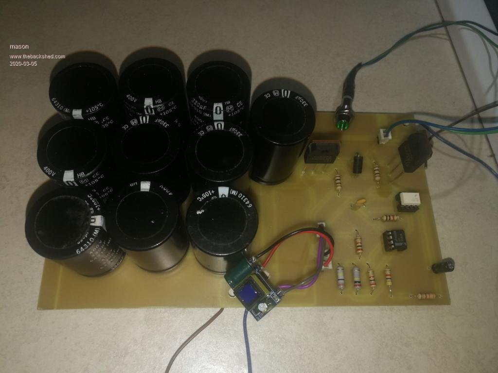
Here is my WarpsHotWater circuit, have not tested it with solar panels, only with 120v power supply seems to work.
Warpspeed Guru Joined: 09/08/2007 Location: AustraliaPosts: 4406
Posted: 09:14pm 05 Mar 2020
Copy link to clipboard
Print this post
Great work there Mason
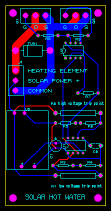
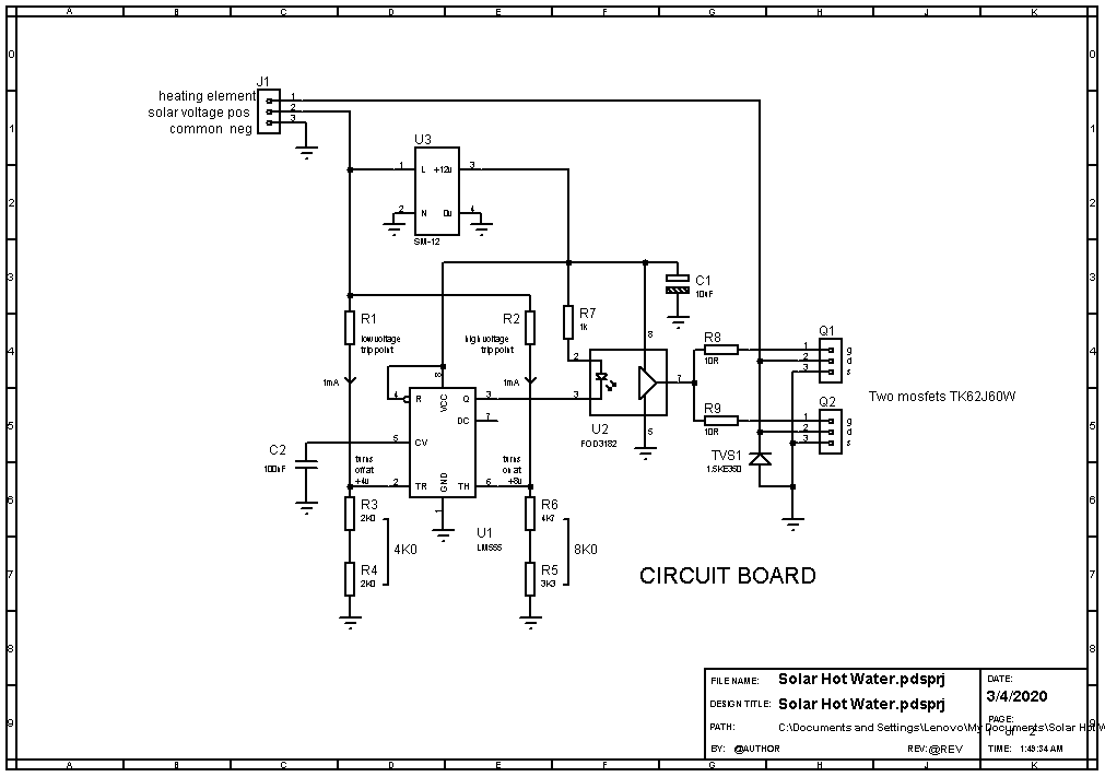
This is the artwork for my own two inch by four inch board:
Cheers, ĀTony.
Warpspeed Guru Joined: 09/08/2007 Location: AustraliaPosts: 4406
Posted: 10:56pm 05 Mar 2020
Copy link to clipboard
Print this post
Here is the parts list:
J1, Q1, Q2 ĀScrew terminal blocks 0.2 inch pitch three way (5.08mm)
U3 Ā Ā Ā Ā Ā12v postage stamp sized dc power supply (from e-bay or Ali)
TVS1 Ā Ā Ā Ā1.5KE350 Transient voltage suppressor (350v)
C1 Ā Ā Ā Ā Ā10uF electrolytic 25v
C2 Ā Ā Ā Ā Ā100nF multilayer ceramic 50v
R1, ĀR2 Ā Ā One watt carbon resistors to suit system voltage as discussed in thread.
R3, ĀR4 Ā Ā 2K0 metal film
R5 Ā Ā Ā Ā Ā3K3 metal film
R6 Ā Ā Ā Ā Ā4K7 metal film
R7 Ā Ā Ā Ā Ā1K0 metal film
R8, ĀR9 Ā Ā 10R metal film.
Mosfets Q1 and Q2 will require an "adequate" heatsink, which in turn depends on the mosfet type chosen, its rdson and the amount of current. Edited 2020-03-06 09:05 by WarpspeedCheers, ĀTony.