| |
  Page 12 of 50 Page 12 of 50   |
| Author |
Message |
poida

Guru

Joined: 02/02/2017
Location: AustraliaPosts: 1389 |
| Posted: 01:16am 13 May 2020 |
 Copy link to clipboard Copy link to clipboard |
 Print this post |
|
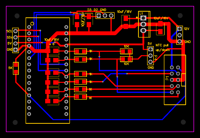
The brainboard nearing completion.
Added:
I2C header, compatible with the nanoverter pinout, for a LCD.
This could be repurposed to become the output for another serial data port
to talk to the LCD should I2C bring too many EMI issues.
Pull up/down jumper for the 10K resistors used with the NTC thermistors
10uF filter caps to clamp down on noise for the 2 digital input/outputs, one of which will be used for the EQ start/stop bushbutton. Maybe 1uF caps would be better. I will try it and see.
I expect to control and obtain data from the board using the USB serial terminal.
This will be a permanent fitting when I build and install it in my home system.
The Raspberry Pi will be able to get the running data whenever needed, such as output power, total energy, volts and current...I probably won't use the LCD much.
I probably will end up with a home system running 2 of these mppt controllers and the nanoverter/Madness 6kW power board inverter. All home built. The data logging, system control and web interface all written by me. (I'm not trying to impress, just noting what has been/will be done..) And remember folks, each and every solar panel we put on the roof causes Angus Taylor to shed another tear. That is why I do it.
wronger than a phone book full of wrong phone numbers |
| |
renewableMark

Guru
Joined: 09/12/2017
Location: AustraliaPosts: 1678 |
| Posted: 12:21pm 13 May 2020 |
Copy link to clipboard |
Print this post |
|
I'm just about to go through my second winter being totally off grid, last one was a bit hard as the wife wasn't familiar with loads etc, now she is more educated it will help.
BUT getting an extra 10% or even 5% will actually make a difference.
I have pretty much run out of room to put panels now.
Half the house is 3s on MPPT, the other half is 2s PWM.
I'll need to do some rewiring, but getting a bit more out of what's there is encouraging.
Cheers Caveman Mark
Off grid eastern Melb |
| |
Warpspeed
Guru
Joined: 09/08/2007
Location: AustraliaPosts: 4406 |
| Posted: 10:56pm 13 May 2020 |
Copy link to clipboard |
Print this post |
|
It probably will not make as much difference as you think.
The situation here is its either sunny and the battery is fully charged by 10Am, or its bloody awful, and nothing plus an extra ten percent is still nothing 
Cheers, �Tony. |
| |
renewableMark
Guru
Joined: 09/12/2017
Location: AustraliaPosts: 1678 |
| Posted: 11:19pm 13 May 2020 |
Copy link to clipboard |
Print this post |
|
Yeah, when it's really cloudy 10% extra won't mean bugger all.
There are times though when the battery never gets to absorb voltage, just hovers around 55 with peaks of 57, then back down again. That extra 10% may help in those situations.
Sometimes I'll get home and the drier will be running, the wife will say, "but look the voltage is really high, it's fine" 
I was just recently going to buy another mppt as a spare in case my other one suddenly gave up, but having something fixable is much better.
Cheers Caveman Mark
Off grid eastern Melb |
| |
kentfielddude
Regular Member

Joined: 09/05/2019
Location: United StatesPosts: 89 |
| Posted: 06:27am 14 May 2020 |
Copy link to clipboard |
Print this post |
|
nice
Edited 2020-05-14 16:27 by kentfielddude |
| |
poida
Guru
Joined: 02/02/2017
Location: AustraliaPosts: 1389 |
| Posted: 11:21pm 15 May 2020 |
Copy link to clipboard |
Print this post |
|
It's time to order some of Mike's (Wiseguy) improved design PCBs.
JCLPCB cost is $7 plus delivery (about $40 for 10 boards)
Anybody here want a board or two?
I will be making an order for 10 boards at least. I want 2 or 3, Mike wants 2
Mark will want a couple...
I will do it the same way I did with the nanoverter boards. Just recover cost.
This is what they look like:
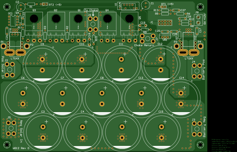
No SMD parts this time so it's old bloke friendly.
It is optional to fit the 3rd MOSFET switch, 2 is good enough.
The cost of parts to build this is about
2 x $7 - MOSFETs
2 x $7 - MOSFET as diodes
2 x $10 current sensors
1 x $10 dc-dc isolated converter
13 x $4.40 470uF 200V caps
and minor stuff
wronger than a phone book full of wrong phone numbers |
| |
renewableMark
Guru
Joined: 09/12/2017
Location: AustraliaPosts: 1678 |
| Posted: 11:59pm 15 May 2020 |
Copy link to clipboard |
Print this post |
|
Good work, through hole is a lot easier.
Will the controller be able to handle 4 boards and limit the current of the combined boards?
If that's possible I'd build 4 of them. 2 to replace my working 80A MPPT(that will stay on the wall in backup) and 2 to replace the Mad PWM unit.
Edited 2020-05-16 09:59 by renewableMark
Cheers Caveman Mark
Off grid eastern Melb |
| |
johnmc
Senior Member

Joined: 21/01/2011
Location: AustraliaPosts: 282 |
| Posted: 12:49am 16 May 2020 |
Copy link to clipboard |
Print this post |
|
Well done, as through hole boards are much easier for me.
I will take 2 boards if they are available.
Cheers john
johnmc |
| |
ryanm
Senior Member
Joined: 25/09/2015
Location: AustraliaPosts: 191 |
| Posted: 02:39am 16 May 2020 |
Copy link to clipboard |
Print this post |
|
I'll grab three boards poida. |
| |
Revlac

Guru
Joined: 31/12/2016
Location: AustraliaPosts: 961 |
| Posted: 02:56am 16 May 2020 |
Copy link to clipboard |
Print this post |
|
Ok I will put my hand up for one, if that's still ok, poida.
Cheers Aaron
Off The Grid |
| |
poida
Guru
Joined: 02/02/2017
Location: AustraliaPosts: 1389 |
| Posted: 07:36am 16 May 2020 |
Copy link to clipboard |
Print this post |
|
I just need to know the numbers so as to place an order large enough for what we want.
I want to do the order Monday.
Mark, I think it will work out fine if you hook up a few of these in parallel.
Have 2 or 3 all on the same input and all with the same output.
You could do it any way you want. I suspect the board will do what it can to produce the 45 Amp max until absorb battery voltage is obtained, then back off.
We already have 2 separate controllers feeding into one battery.
Edited 2020-05-16 17:40 by poida
wronger than a phone book full of wrong phone numbers |
| |
renewableMark
Guru
Joined: 09/12/2017
Location: AustraliaPosts: 1678 |
| Posted: 09:22am 16 May 2020 |
Copy link to clipboard |
Print this post |
|
I have seen my system put out 140A and that was with prob 1/3 panels switched off.
God knows what it can do under ideal conditions when it's all on.
It's over panelled like that so when it's cloudy it still actually makes a decent amount, but that dangerous burst of sunshine can pump huge amounts into the battery and root it good and proper.
Ideally I would love to have the panels all permanently on and have a controller clamp the max amps to 100A so the battery doesn't cop a hard time.
Sorry if this clutters up the thread, but it's an important issue for anyone that runs the entire house fully off grid (on flooded acids).
If it's just not possible with this unit or it's just too much work, that's fine, I'll still build them as a backup and search for another solution to my problem.
I'll grab 4 either way.
Edited 2020-05-16 19:27 by renewableMark
Cheers Caveman Mark
Off grid eastern Melb |
| |
poida
Guru
Joined: 02/02/2017
Location: AustraliaPosts: 1389 |
| Posted: 09:28am 16 May 2020 |
Copy link to clipboard |
Print this post |
|
sure thing.
have 3 boards all limited to 33A
They will try to put up to 33A each but no more.
This is why I want o do this project....
Edited 2020-05-16 19:31 by poida
wronger than a phone book full of wrong phone numbers |
| |
renewableMark
Guru
Joined: 09/12/2017
Location: AustraliaPosts: 1678 |
| Posted: 09:40am 16 May 2020 |
Copy link to clipboard |
Print this post |
|
That would work....... but, say the east array in the morning can put out 80A on it's own, but it's on 2 boards which are limited to 33A, then a potential 80A is not achieved.
I'm wondering if another approach may be needed, like the hall sensor idea we discussed a few months ago. Perhaps it could turn off unneeded strings with SSR's?
I think I'm distracting and holding up your project mate.
Just build it the way you think it needs to be done, I think my situation is a bit rarer than most.
Edited 2020-05-16 19:42 by renewableMark
Cheers Caveman Mark
Off grid eastern Melb |
| |
noneyabussiness
Guru
Joined: 31/07/2017
Location: AustraliaPosts: 506 |
| Posted: 10:10pm 16 May 2020 |
Copy link to clipboard |
Print this post |
|
Morning all, poida, ill take 2 of each if they on offer, just pm details and cost, ill be there.... thank you in advance..
I think it works !! |
| |
poida
Guru
Joined: 02/02/2017
Location: AustraliaPosts: 1389 |
| Posted: 12:30am 17 May 2020 |
Copy link to clipboard |
Print this post |
|
Mike asks
Are there any other current sensor pinout/footprints you would like incorporated
in the PCB before we commit to the order on Monday.
wronger than a phone book full of wrong phone numbers |
| |
wiseguy

Guru
Joined: 21/06/2018
Location: AustraliaPosts: 1000 |
| Posted: 12:37am 17 May 2020 |
Copy link to clipboard |
Print this post |
|
Clarification required - there are 3 types of current sensors currently provided for.
It was the high current external connectors (6 required) that need to accommodate the 40+Amps for input / output / choke connectors that I was going to ask about. if so I need the details (type & pinout) today asap
Is there an alternative connector anyone wants me to consider apart from the 4 pin ones that I chose ? They are ~$5 for 20 from aliexpress - I will be posting again shortly with extra details for anyone that wants to get stuff ordered on the slow boat from china.
If at first you dont succeed, I suggest you avoid sky diving....
Cheers Mike |
| |
wiseguy
Guru
Joined: 21/06/2018
Location: AustraliaPosts: 1000 |
| Posted: 12:53am 17 May 2020 |
Copy link to clipboard |
Print this post |
|
Some Notes on the PCB.
The high current screw connectors are available new from:
https://www.aliexpress.com/item/32811408567.html?spm=a2g0s.9042311.0.0.63784c4dRK1EiS
There are 20 in a "lot" for around $4.70. Shipping for 1 lot is $2.72 and wait up to ~50 days. If you pay ~$8.30 for EMS epacket the wait is 13 to 20 days.
If there is a suggestion for a different (In OUT) connector & footprint details (~40A!) there is still time for it to be included but be quick.
The board will accommodate 3 types of DC/DC converter, pinouts of SPU01 Meanwell, RP1212 Recom and IE1212 Xp or TME1212 Traco.
The current sensors that could be used are ACS758, LTS25-NP or LTSR25-NP types ( the 4th "R" pin needs to be cut off ) perhaps there are others also.
If at first you dont succeed, I suggest you avoid sky diving....
Cheers Mike |
| |
shallowal
Regular Member
Joined: 26/07/2018
Location: AustraliaPosts: 58 |
| Posted: 06:17am 17 May 2020 |
Copy link to clipboard |
Print this post |
|
Hi Poida,
I'd like a couple of boards as well thanks.
 Allan Allan |
| |
poida
Guru
Joined: 02/02/2017
Location: AustraliaPosts: 1389 |
| Posted: 06:42am 17 May 2020 |
Copy link to clipboard |
Print this post |
|
Including my 2 boards, we all have added up to 15 so far.
The cost for 20 boards is $166 AU, about $8 a board. You guys pay
for postage from my location to yours.
I suppose you better have a brainboard too. These are about $35 for 20 boards
including DHL freight. $1.50 each
Not sure if both board orders can be combined into the single DHL delivery..
The firmware is progressing. I have barely functional code running on a prototype
today, there is a fair bit to complete.
But the primary function of MPPT is working quite well. Once the battery gets "close" to the absorb voltage, MPPT is stopped and simple PWM is used to take the battery up the last one or two volts. I use PWM in an attempt to drive the output voltage with less RMS voltage error, that is, a bit smoother.
So that is working OK now. Edge conditions such as battery disconnect or solar connect/disconnect are handled well.
I have only blown one thing up so far. The on board 5V regulator on the Nano. Things went smoky when I powered the Nano with 12V via "VIN" pin while connected to a laptop via USB. Something to examine later I think.
That you all are wanting boards shows a degree of confidence in my eventual delivery of usable software. I am not used to working like this and so I will need to be transparent with the progress and problems as I go.
But at this stage I have something that is a good start.
I finally connected the remaining 3 panels to the East facing roof array and then connected the prototype and got good power out of it. (and good behavior as it started up and ran)
Onward and upward. Oh, is that what I think it is? Beer O'Clock! Yes.
Edited 2020-05-17 16:51 by poida
wronger than a phone book full of wrong phone numbers |
| |
| |
Page 12 of 50 |
