
|
|
Forum Index : Electronics : 150V 45A MPPT - roll your own
| Author | Message | ||||
| poida Guru Joined: 02/02/2017 Location: AustraliaPosts: 1392 |
Wiseguy: No, I did not want to suggest the expensive core was a viable choice for this project. After clicking on "coil data" button we get a list and the website had highlighed in Green, which means "very good" in their view only one core which was that expensive one. Maybe there are commercial forces at work. This part of the discussion concentrating on inductors is my effort to show how one can develop a suitable choice for this particular project via trial and error, but taking some sort of reasonable starting point to work from. I have experience with these TDK E core ferrites and I want to use them if possible since I already have a range of them here on the bench. By all means we should see how the sendust toroid based inductors work out. But I won't be doing that. So I provide the path for others to do the work with sendust cores by showing how it's done. The code I posted on page 17 is perfect for sorting out good from bad inductors. It's one thing to make an inductor of the correct value, but an entirely different thing to see how it works with the large DC current present with typical operating conditions. Inductance changes as a function of applied DC current. And temperature. And just about anything else. The test code, a current sensor and a 2 channel oscilloscope is all the gear you need to determine if the inductor will take it or not. And a 1 Ohm load good for 3kW. Saturation of these TDK cores is not too sudden as to become a problem, in my view. Below are 2 inductors, with power levels 1500,2000,2500 and 3000W 110V inout, 20kHz, approx 1 Ohm load White traces are the 4 power levels. Their scale is 25Amp/div, with zero current where R8 marker is located. We can see how at 3000W things have not got out of control with potentially damaging current levels passing through the MOSFETs. Things seem to be OK to me right up to 2500W which is the design limit. That both inductors are OK to 3000W indicates that there is some safety margin here. The "good" one, about 36uH 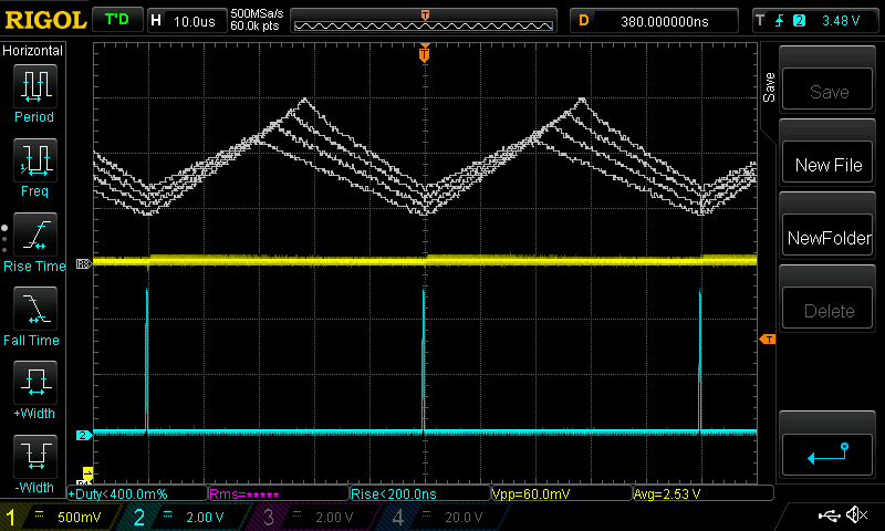 This is the latest one I made using the $26 core and 1.6mm gap  The latest inductor measures 39.6uH using the LCD meter. Edited 2020-06-07 17:40 by poida wronger than a phone book full of wrong phone numbers |
||||
| Warpspeed Guru Joined: 09/08/2007 Location: AustraliaPosts: 4406 |
The information to design a suitable choke from scratch is readily available, and its then just a case of selecting something straight from a manufacturers catalogue. The biggest problem then, is getting your hands on just one core. �The manufacturing company sales rep says "yup we have those in stock, they come in boxes of fifty, only eighteen dollars a core". So how many of these $900 boxes do you wish to order? When you say you only want one core, he just laughs and hand hangs up the phone on you. If I was building something like this for myself right now, I would sort through piles of junk ferrite and various odd toroids I already have here, and pick out something odd and very likely totally obsolete that would work particularly well. � But that would be absolutely useless for other Forum members. Specifying something for a popular open source Forum project, something readily available off the shelf, in one off quantities, and at a reasonable cost can be quite limiting. Especially in the larger sizes. The core manufacturers just are not interested in dealing direct with the public. They have pallet loads of the things in their warehouse, and its just not worth their while. They deal in hundreds or thousands only. The component houses are not interested in carrying stocks of weird things that might remain on the shelf unsold for years. Its a really big problem for a project like this. Edited 2020-06-07 20:24 by Warpspeed Cheers, �Tony. |
||||
| nickskethisniks Guru Joined: 17/10/2017 Location: BelgiumPosts: 428 |
Poida, One thing I notice, you don't use full potential of those cores, I think you know that right? If I see your inductors with pvc insulated wires you can easily double your ratings using enameled wire and use full potential of the winding area. I use a 4A/mm� guideline, I have the feeling this is safe used without cooling. When used with forced cooling you can easily double or maybe multiply by 2,5 but since we want a reliable unit we must use the conservative ratings. Otherwise we better use a commercial unit. About the ripple current, I think that�s the reason I added those MKT capacitors on input and output, they should help a bit, but 4.7uF is to little for the whole period I know, the duty cycle is to low with high differential between in and output, the capacitors need to work. (the MKT are more there for minimize the voltage spikes) On the output we can always add an extra high ripple capacitor/bank, if battery is to far away. There are also the capacitors in the inverter that could help when placed close by. In my case I plan to use output diodes on the controllers so they are decoupled a bit so I don�t think they would help that much. |
||||
renewableMark Guru Joined: 09/12/2017 Location: AustraliaPosts: 1678 |
Jesus, I went away for a week and found a mountain of reading to catch up on. Poida, no rush on the boards. Cheers Caveman Mark Off grid eastern Melb |
||||
| wiseguy Guru Joined: 21/06/2018 Location: AustraliaPosts: 1017 |
Tony thanks for capturing & more eloquently describing the main message I was trying to convey. I know Peter you & I (& a lot of others) are able to get the right result from what we do with what is on hand. But others who want to take advantage of building their own devices want a fairly fail proof recipe to follow, that will work without heartache. I tend to over engineer a project like this to the 150% mark so that when others try to copy it sometimes reusing stuff on hand they can get it wrong to a fair degree and it will still perform admirably. If it came across that I was in any way trying to debunk the great research and results Peter has got to so far is again the wrong message. If others without a lot of electronics background are going to proceed to building the MPPT controller they should purchase the exact parts that Peter is using albeit not cheap cores and follow the published design as closely as possible. They will still save a small fortune on a commercial product and be able to service it. If you are brave & keen then by all means build a saturation tester grab some ferrites or sendust out of your parts bin and have some fun learning. Nicks I agree that the winding window in a perfect design is usually full. However when we are already bordering/entering saturation I see the main benefit to be had is not that we can double the energy throughput further by using thicker enamelled wire but that there would be less resistance and losses & the choke will run cooler which is still a very worthwhile reason to do it. Personally when I get to currents in excess of 30A & when there is less than 10 turns, I like using copper foil. But that requires 25 micron polyester tape & suitable copper sheet or foil at hand and will be a subject for a post of its own sometime. I love my electronics to run as cool as as is practically achievable before I consider adding heatsinks and fans, that helps ensure longevity. If at first you dont succeed, I suggest you avoid sky diving.... Cheers Mike |
||||
| renewableMark Guru Joined: 09/12/2017 Location: AustraliaPosts: 1678 |
Found this seller $235 for 30 units or 15 sets $7.83 per half. Looks like these are ungapped Does this power supply look ok? Edited 2020-06-08 10:26 by renewableMark Cheers Caveman Mark Off grid eastern Melb |
||||
| poida Guru Joined: 02/02/2017 Location: AustraliaPosts: 1392 |
Mark: the power supply looks fine for what you might need when building and testing the controllers. After that's done you will find it useful now and again, if only charging batteries of any and all types. The supplier of the ferrite cores looks like a great find. That price is about 1/2 RS price. wronger than a phone book full of wrong phone numbers |
||||
| poida Guru Joined: 02/02/2017 Location: AustraliaPosts: 1392 |
I have done efficiency tests where I vary the pwm frequency. About 2000W output, 110V in, 47V out 20kHz: in 106.4V, 20.2A, 2150W out 47.8V, 42.7A, 2041W, 94.9% conversion efficiency 37A ripple current 40kHz: in 106.6V, 20.7A, 2200W out 47.8V, 42.6A, 2036W, 92.5% 21A ripple current 80kHz: in 109.4V,20.7A, 2264W out 47.1V, 44.0A, 2072W, 91.5% 11.5A ripple It shows to me there is some switching loss here. We have not explored variations on gate drive voltage, resistor and drive IC yet. The higher current equivalent of the TLP-250 might be a good choice, coupled with 4R7 resistors.... High ripple current can cause reduced life of the output filter caps and also lead acid batteries can have reduced life when fed large voltage or current ripple. I will find the reference for this later. Placing 2 inductors in series halves the ripple, but doubles copper and core losses. My view is these switching losses @20kHz are about 50W, core and copper losses total about 1/10th of that. So I want to use 20kHz pwm if possible. It might be useful to decide how hard you will be driving the converter. In my case, I will probably never exceed 1500W due to the array's orientation and other reasons. So I could be happy with a single inductor 20kHz converter. Some of us might be planning on hammering it at 45A all day, in which case 20kHz and two inductors might be the better choice. I want some time to read the above comments, to do them justice. And I must go to the supermarket now. Gives me something to think about when pushing the trolley.. wronger than a phone book full of wrong phone numbers |
||||
| Warpspeed Guru Joined: 09/08/2007 Location: AustraliaPosts: 4406 |
O/k just for giggles, I fired up my ancient Micrometals buck regulator choke design software and plugged in 200uH, 50 amps, 150volts dc input, 50 volts dc output, 20Khz, to see what the oracle within came up with. Core, T520-2 this is a real monster, 5.2 inches in diameter and 1.6 inches tall !! Turns, 101 5 AWG gauge wire, that is 4.6mm diameter, or 16.8mm square. Fill, 35% of hole occupied. DC resistance 14 milliohms 98% of initial permiability still remaining at 50 amps !! Power loss in the core at 20 Khz 1.03 watts. Power loss in the copper winding 36.2 watts Temperature rise over ambient 38 Celsius. This thing is going to easily go to several hundred amps before it saturates, only thing that limits it would be the temperature rise of the winding. It would also make a very decent pwm inverter choke. Under the above operating conditions, 150v in, 50v out, and 20Khz, the on time will be 12.5uS and the off time 37.5uS (3:1) (150v to 50v) and the ripple current works out to be 6.25 amps peak to peak. The core loss is so very low at 20Khz, a much higher pwm switching frequency could be used to reduce the ripple current even further. As luck would have it, these are available from the US (not fake Chinese) on e-bay at the moment for $53 delivered. Probably not that bad for a 132mm diameter toroid. https://www.ebay.com/itm/Micrometal-Iron-Powder-T520-2-OD-5-2-inch-Single-Core-/283441608487 Cheers, �Tony. |
||||
| poida Guru Joined: 02/02/2017 Location: AustraliaPosts: 1392 |
$53 US is about $78 AUD plus credit card conversion take and GST? It still is a good price I might get one or two just for seeing what they can do. The seller says there are +10 stock available. 101 turns is a bit to ask of me tho, I am lazy. The good E ferrite with 7 turns of 5.5mm2 Earthing cable has a DC resistance of 4 milli Ohms. At the 44A test current of my above 2kW pwm tests, the I2R loss is 44 x 44 x 4 E-3 = 7W. The core losses? Way beyond my ken. wronger than a phone book full of wrong phone numbers |
||||
| Warpspeed Guru Joined: 09/08/2007 Location: AustraliaPosts: 4406 |
The thing about the dash two core material is it has a very low permeability, only about ten I believe. It virtually becomes an air cored inductor. That is what makes it almost impossible to saturate, and why the core losses are so very low. The down side of that, is it requires a LOT of turns, and those turns all add to the dc resistance, and the power loss and the temperature rise. But its not going to either blow up or saturate if it gets a massive current overload for several seconds. That could be a mosfet saving feature in a pwm inverter, as the choke will not lose any ac impedance. Fifty volts and fifty amps is 2.5Kw. Thirty eight watts total power loss in the inductor is only 1.5% of that. The inside diameter of the hole is 78.2mm, so using the circles within circles calculator: https://www.engineeringtoolbox.com/smaller-circles-in-larger-circle-d_1849.html It should be possible to fit 101 turns of wire with an absolute maximum outside diameter of 6.75mm through the hole. I may grab a couple myself while they are still available. Cannot think of a use for it right now, but in a few weeks or a few years it may turn out to be ideal for something. Cheers, �Tony. |
||||
| Warpspeed Guru Joined: 09/08/2007 Location: AustraliaPosts: 4406 |
O/k just looked up 5 AWG wire, and its 1.0254 ohms per Km. https://www.rapidtables.com/calc/wire/wire-gauge-chart.html So my magic inductor software says the resistance with 101 turns is going to be 14 milliohms. Fourteen milliohms, divided by 1.0254 ohms = .0136 Km = 13.65 metres of wire. Cheers, �Tony. |
||||
| poida Guru Joined: 02/02/2017 Location: AustraliaPosts: 1392 |
I think these are the ferrite beads I am using on all 4 MOSFET and diodes https://www.altronics.com.au/p/l5250a-4mm-ferrite-suppression-bead/ wronger than a phone book full of wrong phone numbers |
||||
| renewableMark Guru Joined: 09/12/2017 Location: AustraliaPosts: 1678 |
It's not really a measurement, but AM radios pick up emi pretty well, you can compare other items to what you want to test. https://www.youtube.com/watch?time_continue=531&v=lXPJvSU8MwI&feature=emb_logo https://www.youtube.com/watch?v=kf2CLsr-uMs Edited 2020-06-08 18:08 by renewableMark Cheers Caveman Mark Off grid eastern Melb |
||||
| Solar Mike Guru Joined: 08/02/2015 Location: New ZealandPosts: 1129 |
Too may turns, I think, the u26 materials would be perhaps better suited for this application, #2 is really for RF applications. They have some good cores that would be suitable, login to their site and use the inductance designers, there are many others that would work well and cost US$6 to 10 range. Cheers Mike |
||||
| Warpspeed Guru Joined: 09/08/2007 Location: AustraliaPosts: 4406 |
O/k Mike, logged into Micrometals, and entered 200uH, 50 amps, 150v, 50v, 20khz as before. It comes up with a lot of weird part numbers which do not correspond to any of the old Micrometals part numbers in my data book. So I selected one, FS-400060-2 that requires 53 turns of 4 AWG, and the losses are lower. Its advertised as selling for six dollars US per core as it was the cheapest listed on the first page. Googled that part number and apparently its Chinese made by a company called Dongbuem. Its being sold by another Chinese company Tangda Sendust. Sendust used to be a good American based company ? https://www.aliexpress.com/item/32814587143.html That $50 US delivered is rather more than six dollars, and not that far short of the $53 US delivered for the original genuine Micrometals part I found earlier, and its coming from China. �WTF ??? Micrometals used to be the largest powdered iron toroid manufacturer in the world based in the US. � Seems they have now gone totally Chinese. Edited 2020-06-08 20:42 by Warpspeed Cheers, �Tony. |
||||
| Solar Mike Guru Joined: 08/02/2015 Location: New ZealandPosts: 1129 |
The last cores I ordered from micrometals came as a set of 4 about 5kg total, freight was only $20 or so, seems with covid19, freight costs have gone through the roof. Micrometals will do samples, or they used to at no cost. I have used these T400 type and they work well, however looking back at the order freight was US$12 per core, now its NZ$42.... Seems the RS ferrite cores with a big air gap would be the most cost effective, I would use them >40 Khz to get the turns and wire loss down. Cheers Mike |
||||
| poida Guru Joined: 02/02/2017 Location: AustraliaPosts: 1392 |
for those of us who want to use screw terminals, the PCB uses terminals with a 5mm x 10mm footprint, and aliexpress has them https://www.aliexpress.com/item/32811408567.html?spm=a2g0o.cart.0.0.777d3c00ckHnF0&mp=1 you may as well order them now, it will take a few weeks. I had a look at the Keystone product range of these terminals and there are none that are 5mm x 10mm available from digikey (that is, we get them next week or something) They do have 5mm x 7mm footprint M4 terminals and I think we could bend the terminals out a bit to fit the holes. something like https://www.digikey.com.au/product-detail/en/keystone-electronics/7797/36-7797-ND/2171009 wronger than a phone book full of wrong phone numbers |
||||
| poida Guru Joined: 02/02/2017 Location: AustraliaPosts: 1392 |
The brainboard v2 have arrived. This is very good turnaround time. Very happy. I plan to send some out Saturday, and others Monday. Please PM me your address. Payment via paypal is preferred and only pay after you get the boards. I am in no hurry at all. I can't post them if I don't have an address. You get both a v1 and v2 brainboard for each powerboard. To confirm who wants boards: Nicks: 2 Mason: 2 (and the small Mad powerboard + nanoverter) Shallowal: 2 Wiseguy: 2 Noneya: 2 Revlac: 1 Johnmc: 2 Mark: 4 (he has plans you know..) Disco4now: 1 Tinyt: 1 Ryanm: 3 and I want 2 This adds up to 24 and I have 25 sets. In the near future, I will start making posts to focus on building the boards and complete system, uploading firmware, various details such as calibration and the functional description etc. It would be great if we could pin posts and update them later with more complete info. But we can't. I think I have a workaround for this. Board cost for 25 sets is $212.44 for the powerboard and bb v1 plus $42.77 for bb v2 adds up to $255.21 or AUD $10.21 per set. This is AUD so if you are in Euroland or the US it's about 1/2 that. I use default postage cost, with the boards in a bubble wrap envelope. I put paper between the boards to reduce scuffing of the surfaces. AusPost is reporting delays in delivery times due to COVID19. I suspect these delays have become smaller in recent times. I can't give you firm arrival dates. If you are ordering parts, I want to say we are to use 4 or 5 of the Fairchild FDH055N15A for both switches and diodes. Don't worry about using 3 MOSFETS as switches. I think 2 is quite enough. So the FDH055N15A is preferred. All parts can be sourced from digikey and RS Components. RS has limited stock of the MOSFETS tho. here is the parts list 45A parts.xls.zip Edited 2020-06-09 18:00 by poida wronger than a phone book full of wrong phone numbers |
||||
| renewableMark Guru Joined: 09/12/2017 Location: AustraliaPosts: 1678 |
Don't post mine mate, I'll pick them up some time, no rush. I got that power supply btw, and ordered a new rifle too  Business hasn't been as bad as expected, thank F. Hey, is the LEM current sensor the one you pull from an aerosharp? That hole looks bloody small to put a wire through. Plenty of those fets on Ali are cheaper than RS, but the only supplier I actually trust there is this one But I'd rather get them from RS and be sure of what's coming and not wait 6 years for it. Edited 2020-06-09 18:51 by renewableMark Cheers Caveman Mark Off grid eastern Melb |
||||
