
|
|
Forum Index : Electronics : 150V 45A MPPT - roll your own
| Author | Message | ||||
| johnmc Senior Member Joined: 21/01/2011 Location: AustraliaPosts: 282 |
Good Day All. Thanks Poida, happy to wait for the boards. cheers john johnmc |
||||
mason Regular Member Joined: 07/11/2015 Location: CanadaPosts: 86 |
I'll wait as well Poida, and I would like to cover your cost for the old version board. |
||||
| tinyt Guru Joined: 12/11/2017 Location: United StatesPosts: 431 |
Hi Poida, I will also wait for both brainboards and glad to cover the cost of the old version plus whatever needs to be covered, I might be able to use the old version brainboard. Thanks. |
||||
| noneyabussiness Guru Joined: 31/07/2017 Location: AustraliaPosts: 506 |
Morning, im with tinyt, just let me know the damage when you are ready.. I think it works !! |
||||
| wiseguy Guru Joined: 21/06/2018 Location: AustraliaPosts: 1016 |
Re PCB manufacturing and hole sizes, not everyone may be aware, but if you order a standard 100 x 100mm PCB prototype from PCBWay the price for the PCB is $5 and they will happily drill 0.3mm via holes. If via holes are specified to be drilled 0.25mm (.05mm less) the same board will now cost $47. (0.15 will cost $170) Unless you are routing very dense boards and need a 0.3mm hole (or smaller). A 0.5mm hole should have less impedance & can carry more current than the 0.3mm & if made 0.8mm can accept most component legs (need to scrape off the resist to solder) and useful when modifying PCBs (adding bits to make it work better.....) . Track width and spacing is another trap, 6/6 mil is ok and will cost $5, 5/5mil would cost you $47 and 3/3 mil would be $131. When designing & looking at a PCB on a computer screen, tracks and holes might look like a super highway with huge holes, but viewing true size is encouraged for a reality check. So it may pay to check the defaults for whatever PCB software you are using and ensure you select a sensible size for the via pads & hole size & minimum track width & spacing or you might wonder why the hefty cost. I'm happy to wait for the updated boards too Peter. If at first you dont succeed, I suggest you avoid sky diving.... Cheers Mike |
||||
| nickskethisniks Guru Joined: 17/10/2017 Location: BelgiumPosts: 428 |
I can wait, you can sent to me after you have sent to the others, I will use this boards as backup since I have allready working units. I Will cover all costs. No need to sent me the sill pads. |
||||
| poida Guru Joined: 02/02/2017 Location: AustraliaPosts: 1392 |
Thanks all for your preferences re: mail out of boards. I will wait the now 12 days or so for bb v2 to arrive. Mark: My order of 10 Nanos has arrived. I will need to repay you in kind (Coopers Green Cans) for your immediate help when I asked. I have found it very worthwhile to build a high power resistor, to apply a load to the converter. Combined with some simple code and a decent DC supply, it permits experiments. I use about 2 metres of 0.9mm steel wire wrapped around something that can stay under water in a 10 litre bucket. I solder leads 4.5mm2 copper from this and take then up to the converter/power board. Usually the resistance is 1 Ohm. This is handy, it means Volts across the resistor = amps flowing through it. I would like to encourage you all to have a bit of a play with the converter, to get a feel for it, before you just get it done and make a charge controller. Some of us here have bench power supplies that give 0 to 30V and 0 to 5A or some other specifications. A bench power supply is really useful and I have used both of mine continually during the development of the project. You can make, sort of, your own by getting a dc-dc converter board from aliexpress/ebay/etc. and combine that with a couple of big 12V batteries for the dc-dc converter's supply. Look for a buck converter with variable Volts output AND variable current output. They come with trimpots, so remove them and put 10K pots in their places, with convenient wiring to allow you to twiddle them. this one or this one maybe this is the sort of thing you could use or others, I'm sure there will be better/cheaper choices. You can get ones that take 30V or more input, can drive 10A output at about 30V or less. That sort of thing. Get that and now you have a constant current source, and variable DC supply. This is good for when you first apply power to the board. You can limit current to about 1A and see if it works OK or not.. without blowing it up. Another constant current source might be one or 2 x 65W 12V car headlights, in parallel, driven by a good sized 12V battery. This will be about 10Amps, maybe a bit more. I would like to hear from other suggestions for CC sources etc. Use this as the calibration source for the 3 current sensors, assuming your DMM can handle this current. You need to be able to apply a current and measure it with the DMM. I like to explore the converter's performance using the below code to see how hot things get, the efficiency of conversion, how noisy inputs are, etc. (it's also good for calibrating things) This code requires you to hook up a potentiometer to A5, 0 - 5V and the code will try to have the converter's output follow the pot's voltage. When I write "converter" I mean the powerboard. Same thing. The powerboard/converter is quite a powerful device. It's a dc-dc converter that can handle 3kW and output 55A. It's quite exciting to be able to control this just from the flick of a finger on the pot. There must be other uses for this thing. Charging batteries? Blowing things up? I have no over current protection in this code. Shorting the output will probably blow the MOSFETs. But driving more than 55A will just cause it to reduce power until it's less than 55A. So use it at your own risk. But if you start from zero output and wind it up a little, you can quickly see if things are OK or going South, before you force huge power through it. I think of it as a proper sized DC supply. If you use the Serial Plotter function, you will get a nice graph of lots of info. Or use the Serial console and you get it in text form. Data that is out put is: Pout/10, Pin/10, Vin, Vout, Iin, Iout, Vsetpoint (from the pot), 200 (to set a scale) It is also good for testing the serial LCD that will be needed. #include <EEPROM.h> #include <SoftwareSerial.h> SoftwareSerial sSerial(7, 18); // RX, TX int pwm,cc,dd; float Vsp, Isp; float Vin,Vout,Iin,Iout; volatile float xVin,xVout,xIin,xIout,tIin, tIout; int oIin,oIout; void get_biquad(float,int,int); void biquad_filter(float *,int); float aa[5][4],d1[5][4],d2[5][4]; float w0[5][4],w1[5][4],w2[5][4]; int bqnp[4]; volatile int f50c,f50; volatile char buf[80],*bp,bcount; void get_biquad(float fc, int np, int idx) { float s,r; int i; float a = tan(M_PI*fc); float a2 = a*a; bqnp[idx] = np; for(i=0; i<np; ++i) { r = sin(3.141592926 * (2.0*i+1.0)/(4.0*(float)np)); s = a2 + 2.0*a*r + 1.0; aa[i][idx] = a2/s; d1[i][idx] = 2.0*(1-a2)/s; d2[i][idx] = -(a2 - 2.0*a*r + 1.0)/s; w1[i][idx]=w2[i][idx]=w0[i][idx]=0.0; } } void biquad_filter(float *val, int idx) { float s; int i; s = *val; for(i=0; i<bqnp[idx]; ++i) { w0[i][idx] = d1[i][idx]*w1[i][idx] + d2[i][idx]*w2[i][idx] + s; s = aa[i][idx]*(w0[i][idx] + 2.0*w1[i][idx] + w2[i][idx]); w2[i][idx] = w1[i][idx]; w1[i][idx] = w0[i][idx]; } *val = s; } void setup() { pwm = 1; pinMode(7,INPUT); // let comparator inputs float, dont drive them internally pinMode(6,INPUT); sSerial.begin(9600); bp = &buf[0]; for(bcount=0; bcount < 80; bcount++) buf[bcount]=20; bcount = 0; pinMode(9, OUTPUT); pinMode(10, OUTPUT); TCCR1A = _BV(COM1A1) | _BV(COM1B1) | _BV(WGM11); TCCR1B = _BV(WGM13) | _BV(WGM12) | _BV(CS10); OCR1A = 1; //OCR1B = 2; ICR1 = 800; TIMSK1 |= (1 << TOIE1); // enable timer overflow interrupt Serial.begin(115200); Vsp = 10.0; Isp = 55.0; get_biquad(0.1,2,0); get_biquad(0.1,2,1); get_biquad(0.02,2,2); get_biquad(0.02,2,3); cc = 0; dd = 0; f50c=0; f50=0; xVin = 0.0898; xVout = 0.0900; xIin = 0.235; xIout = 0.244; tIin = 0.00; tIout = 0.00; oIin = 511; oIout = 511; Serial.println("setup complete"); } ISR(TIMER1_OVF_vect) { OCR1A = pwm; // pin 9 // OCR1B = pwm; // pin 10 f50c++; if(f50c > 399) { f50c=0; f50=1; } } void loop() { int a0,fa,fi,nupwm; float p,e; char fbuf[10],gbuf[10],hbuf[10]; // voltage setpoint via pot on A5, 0 to 45V Vsp = Vsp * 0.99 + 0.01 * 60.0 * analogRead(5)/1024.0; // get output voltage Vout = xVout * (float)analogRead(2); biquad_filter(&Vout,0); // get input voltage Vin = xVin * (float)analogRead(0); biquad_filter(&Vin,1); // get output current Iout = - tIout + xIout * (float)(analogRead(3) - oIout); biquad_filter(&Iout,2); // get input current Iin = -tIin + xIin * (float)(analogRead(1) - oIin); biquad_filter(&Iin,3); if (f50 == 1) { f50=0; nupwm = pwm; if ( Vin < Vsp) // if input V is less than output V, shut down nupwm -= 5; if (Vout < Vsp && Iout < Isp && ( Vin > Vsp)) nupwm ++; if (Vout > Vsp || Iout > Isp || ( Vin < Vsp)) nupwm --; if (Iout > Isp) nupwm -= 5; // clamp to reasonable values if (nupwm > 799) nupwm = 799; if (nupwm < 1) nupwm = 1; pwm = nupwm; // write out LCD data, one byte at a time sSerial.write(buf[bcount]); bcount++; if (bcount > 79) { bcount = 0; sSerial.write('$'); } } if (dd++ > 200) { dd=0; Serial.print(Vout * Iout /10.0); Serial.print(" "); Serial.print(Vin * Iin /10.0); Serial.print(" "); Serial.print(Vin); Serial.print(" "); Serial.print(Vout); Serial.print(" "); Serial.print(Iin); Serial.print(" "); Serial.print(Iout); Serial.print(" "); Serial.print(Vsp); Serial.print(" "); Serial.print(" 200 "); Serial.println(); /* for (a0=0; a0 < 8; a0++) { Serial.print(analogRead(a0)); Serial.print (" "); } Serial.println(); */ dtostrf(Vin,4,1,fbuf); dtostrf(Iin,4,1,hbuf); sprintf(bp,"In %4sV %4sA ",fbuf,hbuf); buf[19] = 20; dtostrf(Vout,4,1,fbuf); dtostrf(Iout,4,1,hbuf); sprintf(bp+40,"Out %4sV %4sA ",fbuf,hbuf); buf[59] = 20; p = Vout*Iout; dtostrf(p,5,0,fbuf); sprintf(bp+20,"%5sW Out ",fbuf); buf[39] = 20; dtostrf(Vsp,4,1,fbuf); sprintf(bp+60,"setpoint %4s ",fbuf); buf[59] = 20; } } here is the serial LCD code. you need a 20 x 4 LCD with I2C and a Nano. Wire things up according to the source code. Easy. The serial LCD expects data coming in pin D10. The above code spits out data on pin 18 which is A4 I think. I like how this approach seperates the interface and pwm in such a way that it permits pwm to run without any risk of mis-timed pulses. #include <LiquidCrystal_PCF8574.h> #include <Wire.h> LiquidCrystal_PCF8574 lcd(0x3f); #include <SoftwareSerial.h> SoftwareSerial sSerial(10, 11); // RX, TX void setup() { sSerial.begin(9600); lcd.begin(20,4); lcd.setBacklight(255); lcd.clear(); lcd.print("Serial -> LCD "); lcd.print("pin D10 for RX "); lcd.print("9600 baud "); delay(2000); } void loop() { int c; while (sSerial.available()) { c = sSerial.read(); if (c == '$') lcd.setCursor(0,0); else lcd.write(c); } } wronger than a phone book full of wrong phone numbers |
||||
| nickskethisniks Guru Joined: 17/10/2017 Location: BelgiumPosts: 428 |
Thanks Poida! I hope to do some digging in your code this weekend, I want it to communicate with one of my rpi's and do some visualisation with nodeRed. Speaking about that, would there be a difference for my code if using the USB interface on the nano itself for communication or if using a max232 connected to a rs232 to USB converter? Edited 2020-06-05 06:46 by nickskethisniks |
||||
| poida Guru Joined: 02/02/2017 Location: AustraliaPosts: 1392 |
Nicks: no difference I think. The mppt code uses 2 serial interfaces of course. The USB serial is for configuration and communicating with an intelligent host such as laptop or raspberry pi. This will need the USB to rs-232 conversion to then go to the MAX232. The other serial interface is transmit only, and intended for writing data to the LCD. This is 5V logic level. Edited 2020-06-05 10:01 by poida wronger than a phone book full of wrong phone numbers |
||||
| poida Guru Joined: 02/02/2017 Location: AustraliaPosts: 1392 |
The 2 pairs of ferrite cores have arrived. Let's make an inductor for the project. And learn why we build it a particular way. I first wound 4 turns and tested it with the LCR meter. 140uH. The specs for this N27 material say it's AL value is 8800uH. This means you should get 8800uH per turn squared. 4 x 4 x 8800 = 141,000nH or 141uH. The LCR meter showed 140uH. This is very close. So the specs don't lie. I put 7 turns around it, with no gap and let's see how it goes. Inductance is now about 450uH. This is way too big. All tests are 57V in, 1 Ohm load, varying output voltages, 20kHz pwm. Yellow is inductor current, 0.5V/div and 0.0202V/Amp so that's 25A/div Zero current is at the "R8" White marker. Light Blue is pwm, i.e. high = MOSFET is switched ON 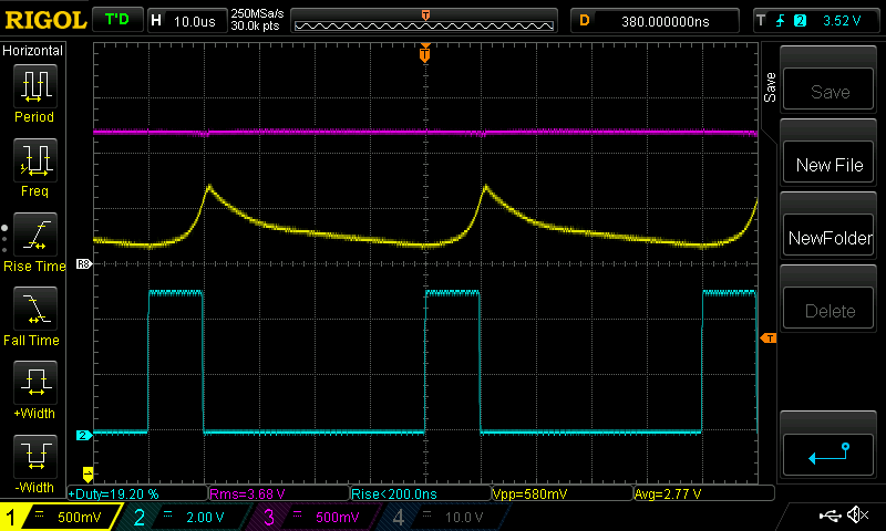 and at a higher power 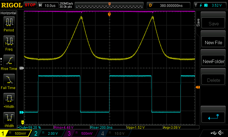 This is of no use for us. It's nearly all ripple current and that's bad. And it's saturating like billy-o. Now this is how the very good inductor I made with 1.5mm gap looks like 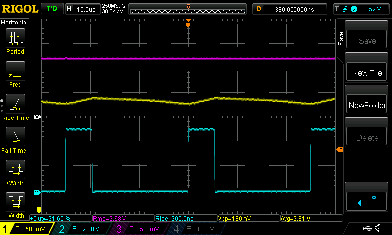 and at higher power 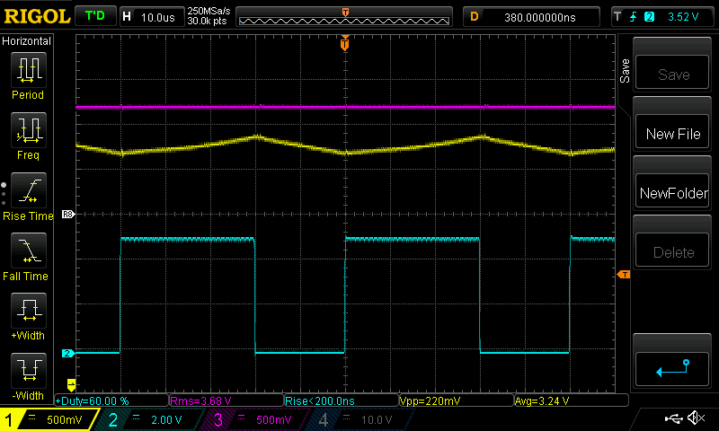 There is proper linear current increasing during the pwm pulse and it decreases in a linear manner when the MOSFET opens. This is good, in that it limits current peaks which are bad for the capacitors, bad for radiated EMI, bad for efficiency and bad for the MOSFETS. This is a good inductor for this project. Now I made a gap between the two halves with 4 business cards. This gap is about 1.5mm, let's see how it changes things.. For a start, the inductance for 7 turns is now 21uH, a lot less than the 450uH. 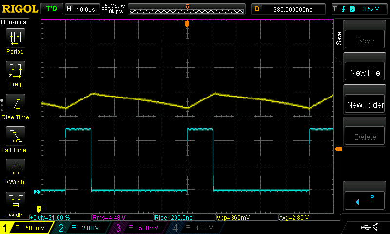 and at higher power 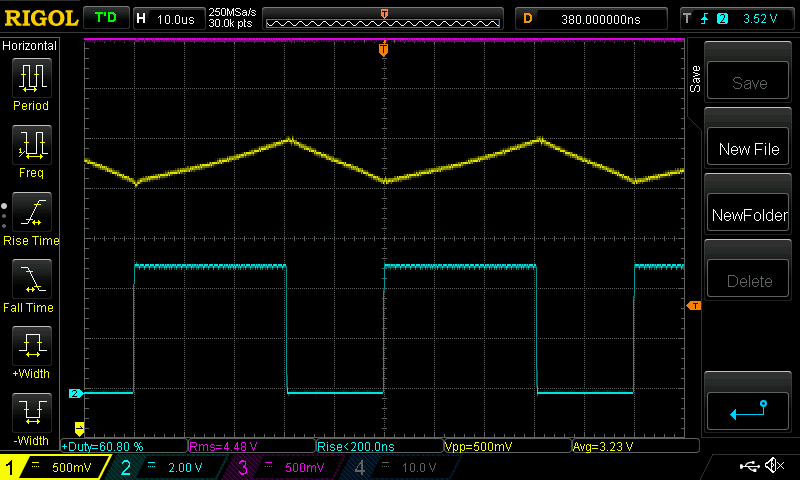 It has completely changed things. Now it looks like a usable inductor for the job. Tomorrow I will show what, if any, difference there is between having a gap in all 3 arms of the core compared with one gap in the middle arm of the core. I think the latter will have less EMI but I can't really measure that. The 21uH inductance contributes to the 25A ripple which is a bit too high. The best inductor I have is about 36uH and so the ripple current is less, down to a more reasonable 1/2 that maybe 12Amps. So tomorrow I try a 1mm gap, see what it looks like and then a 1.5mm, both only gapping the middle arm. And finally I will need to see what it looks like with 110V input. wronger than a phone book full of wrong phone numbers |
||||
| SYM-1 Newbie Joined: 18/10/2019 Location: New ZealandPosts: 40 |
So this is with two yellow inductors. Can you take a photo of the inductor complete with business cards please? Grant Persistence is the key |
||||
| poida Guru Joined: 02/02/2017 Location: AustraliaPosts: 1392 |
these ferrite cores are 70/33/32 TDK items, see above for the RS Components part number. The core material is N27, which is has a smaller AL value of 8850nH compared with the slightly better? stuff N87 at 9700nH 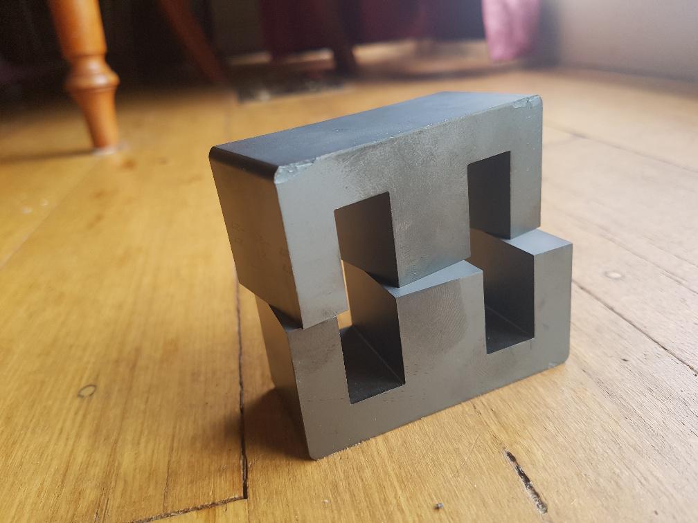 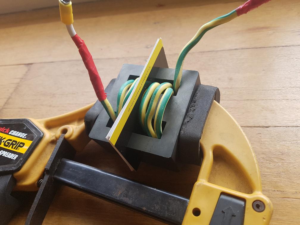 wronger than a phone book full of wrong phone numbers |
||||
| wiseguy Guru Joined: 21/06/2018 Location: AustraliaPosts: 1016 |
Peter, I found this website many years ago and have found it invaluable in designing magnetics for switch mode power supplies. For a quick approximation of inductor or transformer design or even as a cross check of your own calculations or design. For this current MPPT design just use the buck design at the top of the list, feed in vmax, vmin, freq, and output V & I and it will have you on your way in no time. The bottom 2 windows that ask for L/H and Delta IL/A are left blank - they are worked out automatically when you press "Calculate". �It also suggests what core size/volume etc to use when you press "Coil Data". �Delta IL gives you an idea of the expected ripple current for the input data you entered. It looks worse at first glance than it is........ the "Help" button gives you a lot more information about how & why and the equations & math involved. Hope it saves you some time & effort. �In an energy storage inductor - as you have found out - the energy can be thought of as being stored in the air gap. Little gap little energy & of course you add gap you change the inductance so juggling is required. Edited 2020-06-06 10:38 by wiseguy If at first you dont succeed, I suggest you avoid sky diving.... Cheers Mike |
||||
| Warpspeed Guru Joined: 09/08/2007 Location: AustraliaPosts: 4406 |
Quite right. Much less external radiation with the gap in the middle, and it works especially well in a buck regulator. The lower the peak to peak ripple current, the less the ac fringing and magnetic radiation will be. Less skin effect in the wire too. If this choke were to be used in some kind of flyback topolgy, gap in the middle would be really bad news. Magnetic fringing around the gap would cause horrific spikes and ringing in the winding. In a buck converter, the voltage across the inductor is severely constrained both ends, so it cannot ring, its all good. For best overall results, stuff as many turns onto that core that will possibly fit, and then open up the gap as required. Max turns will give you highest possible inductance versus saturation combination. Cheers, �Tony. |
||||
| poida Guru Joined: 02/02/2017 Location: AustraliaPosts: 1392 |
Ta Warp, I get how you need to use the hole to the best advantage. I get 7 or 8 turns of something large enough to carry the current. So today I tried with a gap of about 0.6mm on the middle arm. Testing today is 110V input, since that is how we will roll anyway. Power level is about 1700W. I did not want to go higher 7 turns. Yellow is inductor current, 0.5V/div, or 25Amps/div Light Blue is pwm 0.6mm gap: 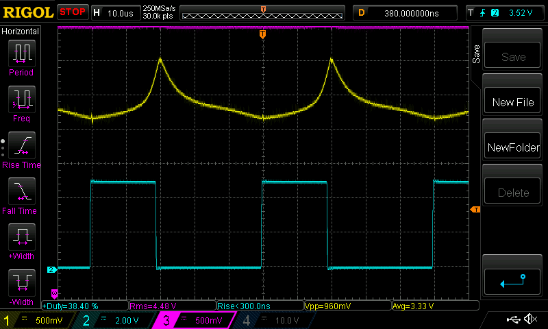 Very clearly saturating. This is not what I want or will ever use. and I thought we need a bigger gap so here is 1.6mm at about the same power level, maybe a bit more: 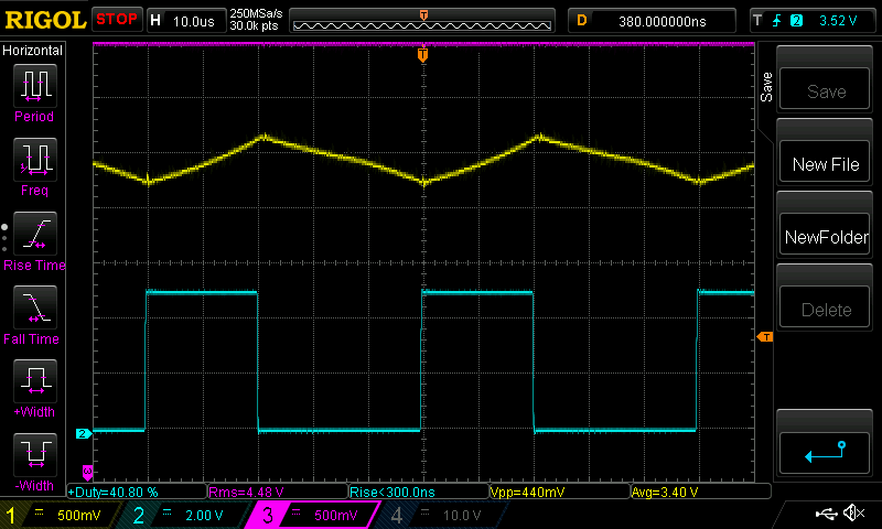 Much better. Here it is at 2500W, maximum power with 110V input. 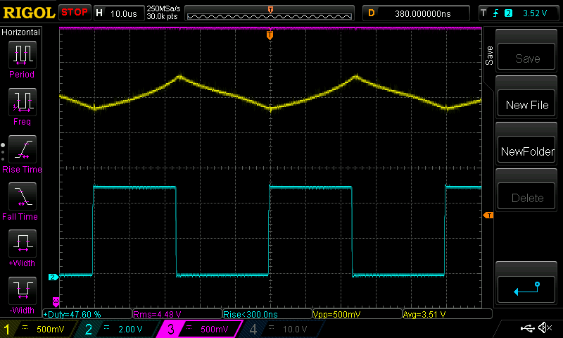 It's just beginning to show signs of saturation (the slight increase in slope during the pwm ON..) I can live with this. The ripple current is about 25 Amps. This could be too big for the capacitors we are using. But Wiseguy says having a big battery on the output also will help suck up this ripple so the caps might not get hot anyway. Wiseguy, in the above post pointed me to an excellent website that helps you determine important facts about buck converters. I plugged the usual specs into it, being 110V in, 50V out, 20kHz pwm, 45 Amps out and I got 76uH for the inductor and 18Amps ripple. This indicates to me I am on the right track with this. The website is from a supplier of ferrite cores. And so the site suggested a particular core for this job. PM114/93. I see that RS-Components stock this core and costs range from AU$244 to AU$355 I think I will stick with the 70/33/32 E core at AU$26 Here is a photo of the ugly workmanship, giving the "1.6mm" gap. 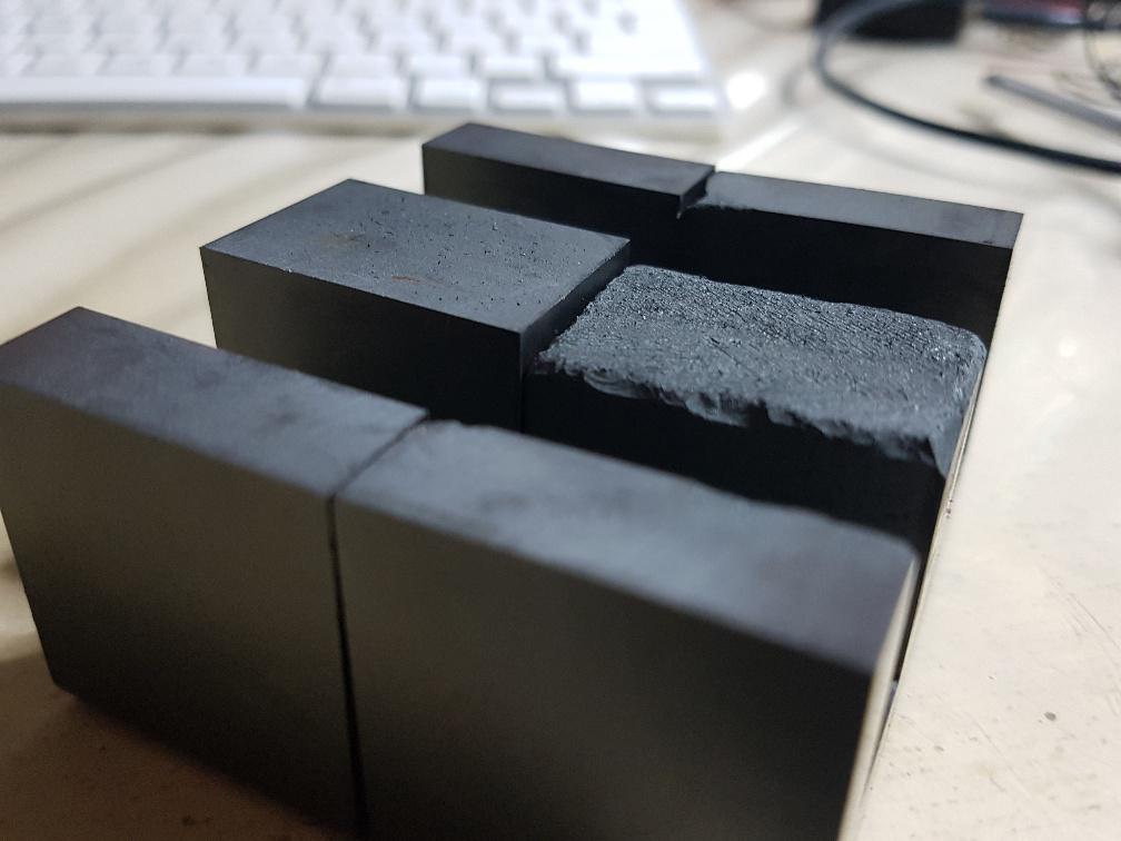 It looks just like the other one really. Not a lot to learn. So 7 turns, 1.6mm gap, $26 E core ferrite E 70/33/32 N27 pair of cores, RS part no. 47-9367 Digikey has them for $15 each, you need two. part no. is B66371G0000X127 I used 2 x 4.5mm2 conductor for the coil. It just fits. job done. wronger than a phone book full of wrong phone numbers |
||||
| Warpspeed Guru Joined: 09/08/2007 Location: AustraliaPosts: 4406 |
Great stuff there Peter  Cheers, �Tony. |
||||
| nickskethisniks Guru Joined: 17/10/2017 Location: BelgiumPosts: 428 |
Poida, I can't figure it out. I'm trying to get the serial monitor working, but I don't get it right. (So just the nano on the usb connection, with the arduino monitor) I'm just using a bare arduino without things connected. So, first thing I need to set, is the baudrate @ 115200. Is there something else that I need to understand? The only thing I don't quiet understand is this: char c, *p; It is used in "void parse_it()". Is it possible the loop you made with serialEvent() is not called at all? Probably some parameter/condition I'm missing. (oh btw, I'm using the code with password protection) Edited 2020-06-07 07:00 by nickskethisniks |
||||
| wiseguy Guru Joined: 21/06/2018 Location: AustraliaPosts: 1016 |
That would be the wrong summary/conclusion to draw - do you really think I would suggest a $250- $350 core as a viable solution for this forum ? Perhaps you could plug in some alternative numbers to see if there are other solutions. Maybe you could try upping the frequency, maybe you could try inductors in parallel or double/triple stacking your Ecores or considering a sendust material or and stacking these can get you to the right solution. As solar Mike suggested & my usual solution is sendust type toroids of which there are some very cost effective hi flux and cool Mu versions with a very high flux density & high saturation ability. �Even an iron core type solution is very viable at 20kHz. �My parts bins have ferrites and sendust toroids and not a lamination in sight so iron is not usually my go to solution. The UK RS site has the EE55 at 3quid for a pair compared to that ridiculous PMpot core price of 140 quid. �If you want to stay with E cores, you should consider stacking 2 or 3 sets with a common winding, Neosid Australia is one source for cost effective EE55 EE70 �cores - or was when I used to deal with them regularly. Sometimes physics just cant be changed. �Just because you want to squeeze a litre and a half into a litre bottle doesnt mean you will ever do it. �If you have fixed limitations such as on time, current, effective cente leg area, material volume, saturation point then energy storage is finite for a given core. �Increasing area, volume, gap, frequency or decreasing amps or on time, changing materials or variations of a mix of these can lead to cost effective solutions. �The site I suggested will calculate the right (minimum) inductance value & maybe a suitable core. The next part of the solution is to create an inductor with gap and turns that satisfies the inductance value & current requirement staying within reasonable saturation levels. �Their inductor core solution suggestions can be used to get more insight into the cross sectional area of the centre leg and effective volume and gap required to get you in the ballpark. The curvature you see in your last cro shot as the current nears maximum is the saturation knee, where current begins to rise exponentially. I try to keep well away from this area especially with ferrites that enter saturation rather sharply. Operating in this region usually causes the capacitors and Fets to have to work harder and increases losses and heat. �As you get into saturation things like magnetostriction can also start to cause the core to whistle & click and become audibly noisy. Keep up the good work. Edited 2020-06-07 09:21 by wiseguy If at first you dont succeed, I suggest you avoid sky diving.... Cheers Mike |
||||
| poida Guru Joined: 02/02/2017 Location: AustraliaPosts: 1392 |
I just sent you the latest code, via email. Before sending I put it into a bare nano, connected and got the menu. When you connect using USB console, this causes the nano to reboot, so it takes a few seconds to respond to anything. Connect using 115200 baud. If using the Arduino program, you type ? in the top text area and then click on "send" button. Then you must get the menu. Some choices in the menu for reasons do not give a prompt at all. eg: A will cause a prompt "Heatsink maximum temperature (degC)" and of course we reply with a temperature. C is one choice, it calibrates Vin. It takes a few seconds. You can also connect to the nano using a terminal program such as putty The comms config should be 115200 baud, no handshake, local echo Again as soon as you open the putty terminal session, the nano will reset. Give it a few seconds then type ? wronger than a phone book full of wrong phone numbers |
||||
| nickskethisniks Guru Joined: 17/10/2017 Location: BelgiumPosts: 428 |
Hi, Your latest code was working in 60s  Thanks! |
||||
