
|
|
Forum Index : Electronics : 150V 45A MPPT - roll your own
| Author | Message | ||||
| Warpspeed Guru Joined: 09/08/2007 Location: AustraliaPosts: 4406 |
A useful way of working out what will fit is the "circles within circles" on line calculator. https://www.engineeringtoolbox.com/smaller-circles-in-larger-circle-d_1849.html For fifty amps, 10mm square copper area would be about right. I would guess that would be about 6mm diameter over the plastic, for single insulated cable ?? Diameter of the hole is 78.2mm Estimated diameter of wire 6mm ?? Using the above magic software, in a perfect world 130 turns should be theoretically possible. Cheers, �Tony. |
||||
| poida Guru Joined: 02/02/2017 Location: AustraliaPosts: 1389 |
No sweat, you can still work out the inductance by using the inductor you make and measuring things with the oscilloscope. Here is inductor of an unknown value (I know it already but anyway..) I have it in the converter board, running at 2000W output. Input voltage 106.6V Output voltage 48.8V pwm width 23.1uS current sensor trace shows a 0.280V difference from start of pwm pulse to end of pulse. At 0.0197V/Amp this means 14.2 Amps See the DSO capture, it shows the nice linear current increase during the period of the pwm switch ON event. Yellow is current sensor output, Light Blue is pwm 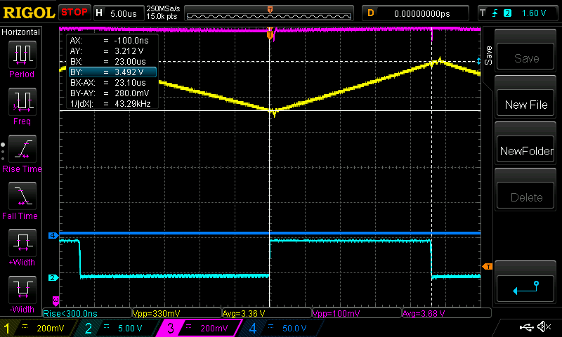 Now, from the fundamental inductance equation L (inductance in Henries) = (difference in Volts) * (difference in time) / current we have L = ( (106.6 - 48.8) Volts * 23.1/1,000,000 Seconds ) / 14.2 Amps Important to note that the voltage the inductor sees is the output voltage subtracted from the input voltage. (It is a Buck Converter when it's all said and done and that is what the inductor is exposed to) So L = 57.8 x 23.1E-6/14.2 = 94 E-6 or 94 uH Let's see what the AUD $500 BK Precision model 879B LCR meter says.. 99.36uH when measured at 10kHz This is close enough for government work (as AvE might say) The testing done in the converter is the best test we can do. It includes the effects of the DC current passing through the inductor and the effect of this current is not to be ignored. I suspect the small difference in values can be due to the about 30 Amp current DC flowing through the inductor, probably bringing down the Al value down a bit. The LCR meter tests components with zero DC current injected into the test. Also, I could have increased the Yellow channel gain, to give a bigger trace to measure, and so get a bit better accuracy. I keep saying, it's real world inductance we need. Not so important what the LCR meter tells us, but for sure, the meter is a great guide for a start point. This is why the test program I posted earlier has value. We can develop a clear image of the worth of the inductors we make for this particular application. Edited 2020-06-27 18:05 by poida wronger than a phone book full of wrong phone numbers |
||||
| nickskethisniks Guru Joined: 17/10/2017 Location: BelgiumPosts: 416 |
A little bit off topic. But since I want to order some toroids to experiment with, I also want to buy some toroids for making small transformers for my active battery balance system. This way I save some transport costs. But if I do some calculation, I need to have a lot of turns for having low core losses. Probably because of the distributed airgap, I'm right to say those micrometal iron powders cores are not really suitable for making little transformers? (I�m talking about +/-50khz) I need to look at soft ferrite cores and not iron powder cores for that purpose? On topic again, I�ve spended quite some time this afternoon reading up about core materials and stuff and wanted to post some questions, but I�ve just reread Warpspeed his post and made some calculations myself, I now understand more about inductors in general. One thing I couldn�t find was what the recommended flux density was for those iron powdered cores. And that�s actually something very important, what I could find on the micrometals site under the 26 material was for 100khz and 140 gauss a power loss of 83mW/cm� nom, 95mW/cm� max, that would be between 350 and 400 gauss for 20khz. datasheet 26 mix It will heavily depend on temperature, active cooling, the amount of windings, etc ( and frequency), so although the material itself before completely saturated @ 13800 gauss, the recommend continuous flux density is only less then 400gauss for 20khz? So soft ferrites will perform the same or better @ high loads, but don�t have that �soft saturation� curve. I see now why they are used a lot for buck or boost regulators. Looking back at your post Warpspeed, apparantly I don't understand everything, why don't you use N = (Erms *10^8)/ (4.44*A*B*f) ? This is the post I will copy to my Onenote account where I started to save my project notes: Edited 2020-06-28 06:49 by nickskethisniks |
||||
| SYM-1 Newbie Joined: 18/10/2019 Location: New ZealandPosts: 40 |
I am having trouble measuring the current swing on my old CRT scope. I am using a shunt to measure current rather than a hall effect device and I get way too much 50Hz hum. Also I am dumping current into LifePO4 batteries. Maybe that has an effect. I must do another trial with a resistor. According to calculation I have about 40uH on my inductor so if I keep my voltage swing to 20V or less I should still be able to do some experiments. Persistence is the key |
||||
| nickskethisniks Guru Joined: 17/10/2017 Location: BelgiumPosts: 416 |
Maybe you can add a small rc filter? I don't know what value you are using, but maybe try one with higher resistance. You can also make a current transformer, if you have another small toroid. Just put a lot of turns on it and load it with a resistor. |
||||
| Warpspeed Guru Joined: 09/08/2007 Location: AustraliaPosts: 4406 |
Ferrite is definitely the material of choice for a high frequency transformer, or an inductor where there is no dc bias. Vastly lower high frequency losses in the core, and the greater permeability of ferrite will produce higher inductance per turn, and produce a much cleaner flatter square wave. So you can get excellent results in a transformer with far fewer turns on ferrite. Powdered iron is much more useful for dc chokes (or sometimes flyback supplies) basically anything that carries a lot of heavy dc current and would normally require a very large air gap. Its extremely lossy though, and temperature rise of the core needs serious consideration. But for dc, powdered iron or steel is King. Ferrite starts to fall on its face above about 330 Gauss, powdered iron goes to at least 10,000 Gauss, possibly 20,000 Gauss before saturation. Its just no contest for a high powered dc choke application. The total flux in the core depends on both the dc component, and the ac component that add directly. The ac and dc parts are worked out quite independently using very different methods. Powdered iron has a very high saturation level, about the same as steel, its enormous. The ac capability is very small, the core losses are so high that temperature rise becomes the biggest factor. The result is, when working out the dc part of the design (amps, turns, and inductance) we can completely ignore the ac part. Its just a tiny ripple on top of the huge dc component. Just calculate the mmf in Orsteads for the particular core, and you can read the percent drop off in initial Al value from the magnetisation curve, and calculate inductance from that. I don't know what the actual flux is, its going to be pretty high, 10,000 Gauss possibly up to 20,000 Gauss for some materials. No real need to know. The ac part of it is exactly the same as for transformer calculations using Faraday's law. Its frequency, number of turns, core cross sectional area, and voltage. From that you can work out the ac flux swing, and the core loss per unit volume. Its exactly as you stated N = (Erms *10^8)/ (4.44*A*B*f) The allowable ac swing might be only 100 or 200 Gauss for example, and the DC part 10,000 or 20,000 Gauss. Only the ac part produces core heating, and its so small compared to the dc part we can completely ignore it when doing the dc part of the design. You can do it that way, but that formula requires an rms voltage. If instead we use the more convenient volt microseconds, that figure can sometimes be more directly applied to published data. On page 24 we have core loss data for -26 material. Its presented both ways. On the left we have core loss in Milliwatts per cm cubed versus flux swing in Gauss. But how hot is that ? On the right we have a table which tells you how many volt microseconds per turn at a particular frequency gives a 15 Celsius core rise for different sized cores. Its a bit rough and ready, but we don't really need to calculate temperature rise precisely, just a rough indicator, warm, hot, impossibly hot... Cheers, �Tony. |
||||
| Warpspeed Guru Joined: 09/08/2007 Location: AustraliaPosts: 4406 |
Shunts are o/k for voltmeters and ammeters because the very low millivolt amplitude output can be very heavily filtered. For an oscilloscope, where you wish to see the actual current waveform, its going to be buried in noise and be pretty much unusable no matter what you do. A hall sensor is a much better approach, especially where there is combined dc and ac, and you need voltage isolation. If its just ac only, a current transformer works quite well with an oscilloscope, but for a project like this, a Hall sensor is really the only thing that is going to give you a relatively clean and usable signal. Cheers, �Tony. |
||||
| poida Guru Joined: 02/02/2017 Location: AustraliaPosts: 1389 |
Another way to measure inductance is to determine impedance. How to do this? (from the BK Precision pdf on using LCR meters) You need a 2 channel CRO or DSO and a function generator. Then do this: 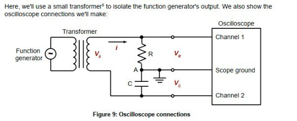 It works just as well when you test an inductor instead of a capacitor. Any transformer will do, I used a 12V 1Amp from a wall wart when I first did this at work. This time I used a large switching PS tranny. FunGen settings: 6V peak to peak output, this is not important. 10kHz sine output And note, the purple trace, which is the voltage across the inductor IS INVERTED. 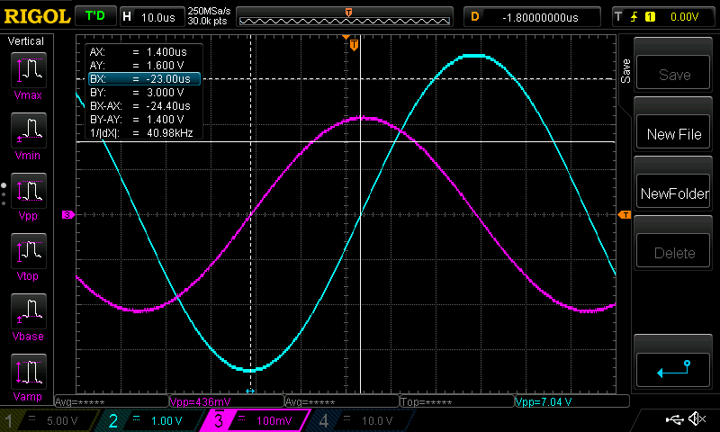 We can see the two sine waves, the Purple sine is leading the Light Blue sine wave in time. Impedance is found from the good old V = IR, or R = V/I In this test: Resistor is 150.6 Ohms Vr (voltage across this resistor) is 7.04V Vi (voltage across the inductor) is 0.436V 10 kHz frequency, this means 100uSec period leading phase angle = 24uS which means 24 / 100 * 360 = 86.4 degrees Ir (current flowing through Resistor AND the inductor) = 7.04/150.6 = 0.0467 Amps Z (impedance or the resistance of the inductor at this frequency) is 0.436 / 0.0467 = 9.3 Ohms @ 86.4 degrees since Z = WL (where W = 2 x PI x frequency) we can solve for L L = Z / W = 9.3 / (2 x 3.142 x 10,000) = 148 uH We didn't need the phase angle but it's useful for working out ESR and other things. The LCR meter shows Z = 9.07 Ohms @ 87.8 degrees and inductance as 144.34 uH This is very much close enough for our purposes. here is the high tech test setup that produced the above results 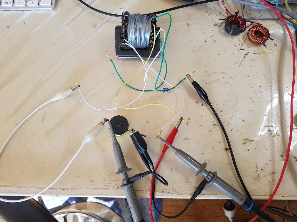 wronger than a phone book full of wrong phone numbers |
||||
| poida Guru Joined: 02/02/2017 Location: AustraliaPosts: 1389 |
I was wondering if I could saturate the large Aerosharp Iron core. I figured to put a lot more turns around it and test it in the standard test: 2000W 110V 1 Ohm load. approximately 20 kHz 27 turns and 258.2 uH Surely that is too many turns. The Amp.turns product must be too much now. In 106.9V, 20.6A, 2202 W Out 49.5V, 42.7A, 2113 W, 96% efficiency Only about 6.3 Amp ripple. This is tiny for the kind of power the board is dealing with. And it did not saturate. The winding for this was the 4.5mm2 pvc insulated PV roof top cable I usually use for just about everything. During the short test, the winding did get warm. 0.107 V at 6.15 Amps DC resistance test means it's 0.107/6.15 Ohms or 17 milli Ohms So there is at least 0.017 x 42.7 x 42.7 = 31 Watts lost in the winding. Probably more when we allow for skin effect for the high frequency AC power. This test was using the HY5110 MOSFET board. If I used the board that has the better FDH055N15A MOSFETS I think it might be a little better again. wronger than a phone book full of wrong phone numbers |
||||
| SYM-1 Newbie Joined: 18/10/2019 Location: New ZealandPosts: 40 |
For my 2 520-2 cores 67 x 25uS for volt microseconds 0.04T(from the chart) And 524 x 2 mm2for 2 cores from page 13 Still 41 turns to satisfy ac loss requirement. At the moment I have 19 turns of 2.3mm dia x3 wires so if I drop the mS by half by going to 40kHz And make my maximum voltage drop 48VDC Say 72V down to 24V I should be able to do some tests Persistence is the key |
||||
| Warpspeed Guru Joined: 09/08/2007 Location: AustraliaPosts: 4406 |
You are definitely on the right track. The saturation limit of steel (and powdered iron) is incredibly high compared to ferrite, but its very lossy. Increasing the turns count does two things, it increases the ampere turns, and it also decreases the volts per turn. So it pushes the dc flux level much higher, which steel can easily handle. And the extra turns reduces the volts per turn, and that reduces the ac flux swing, and the ac losses.  If you look at the steel chokes typical in higher voltage grid tie inverters, there are usually two windings, each of two layers, and possibly twenty to twenty five turns per layer. Total turns count might be in the region of eighty to one hundred turns. These might supply a pwm inverter off a 200v to 250v dc rail at maybe ten amps. There will only be about 2v to 3v per turn, a fairly large core cross section, and at 20Khz to 25Khz, the ac flux swing will be extremely small. But the ampere turns will be enormous, perhaps 1,000 ampere turns on a steel choke like that. Its a completely different design approach to using a ferrite choke which can stand a much higher ac flux swing, because the core losses of ferrite are extremely low. But too many extra turns on a ferrite core would require an impossibly large air gap to stay safely below saturation. To get the best from powdered iron or steel in a choke application, its usual to see a far higher turns count than would be usual with a ferrite core. Cheers, �Tony. |
||||
| Warpspeed Guru Joined: 09/08/2007 Location: AustraliaPosts: 4406 |
See how that goes. Its really all about safe temperature rise. Losses in the wire go up square law with current. If there is plenty of sunshine, losing a few watts is no big deal. When the sky is grey and horrible, and solar is minimal, copper losses will shrink to insignificance. Core losses however, will be there all the time, even at zero load. Cheers, �Tony. |
||||
| poida Guru Joined: 02/02/2017 Location: AustraliaPosts: 1389 |
I just tested the little choke, from inside the Aerosharp. Some inverters have two of these inside. It's marked 2.45mH and it's good for 10 Amps. The LCR meter agreed it was 2.45mH. I took off 3/4 of the turns, so I would expect 1/16th inductance. 2.45/16 = 153uH. The LCR says it's 188uH. Whatever, probably bumbled the removal of turns. Standard test: 110 V in 2000W 1 Ohm load 20kHz pwm In 108.9V, 20.0A, 2178W Out 49.9V, 42.5A, 2120W, 97.4% efficient. Wow. 6.3A ripple The winding gets rather hot fairly quickly. 23 turns or 3.6mm2 solid conductor copper, enamel coated. The core dimensions 41mm wide x 84mm long x 35mm high No saturation at all. Here it is at 2500W or so 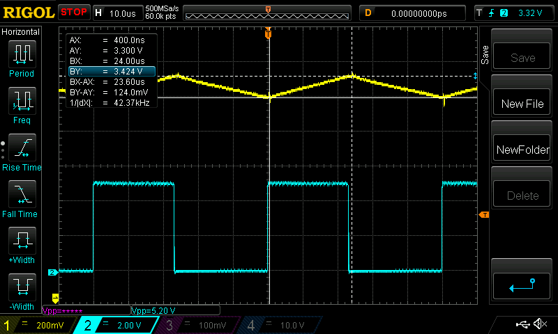 Very straight line for the Yellow (inductor current) trace. 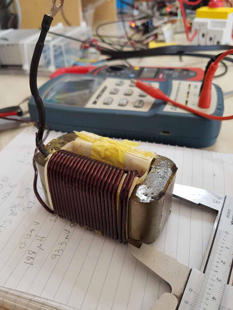 I did not believe my measurements so I repeated the 2kW test. Again similar results. This core would be ideal for light duty versions of the mppt controller. For instance my East facing roof top array that never delivers more than 1200W or so due to the timing of when the North facing array chimes into full power. Onward and upward. Here is the first version of the mppt code I feel ready to share. NTC voltage to temperature not fully tested yet. mpptv4_24-6-20_NTC_works_well.zip I am running the East facing array with a prototype mppt running this code. There are no NTC thermistors used in that build. wronger than a phone book full of wrong phone numbers |
||||
| Warpspeed Guru Joined: 09/08/2007 Location: AustraliaPosts: 4406 |
Peter, if you have another of those chokes, separate the two windings and place them in parallel instead of in series. You will then have half the original turns, should be a quarter the inductance about 612uH. That should produce a ripple of around 1.5 amps. Peak current will be diminished everywhere, and efficiency should rise very slightly. It should I expect reach at least 30 to 35 amps before it begins to saturate, possibly a tad more, it depends on the original air gap. There will now be two parallel windings, and a quarter of the original dc resistance, and the full original exposed area to dissipate the heat. Twice 3.6mm2 should be good for 30 amps dc continuous, and that should fit in fairly well with the expected saturation limit. Double check the phasing, but making diagonal connections that cross over should be correct if memory serves. Should be able to measure about 612uH before you power it up, just to make absolutely certain. As many of us already have these weird steel chokes, there may finally be a practical use for them  Edited 2020-06-29 16:03 by Warpspeed Cheers, �Tony. |
||||
| nickskethisniks Guru Joined: 17/10/2017 Location: BelgiumPosts: 416 |
Maybe only suitable for European people over here, I found an EU based online shop for buying those C -cores, I didn't sent them an email but it looks like they can deliver those c-cores on demand. It's not very cheap, and there is a moq for goods not in stock. There are links to datasheets so the site is useful anyway. C-cores They do sell iron dust cores as well like the t400-26d, and prices are not that high a guess: T400 Or anyone wants to buy this big boy? T650 I don't have experience with this shop, but it looks like an interesting shop to find out. |
||||
| poida Guru Joined: 02/02/2017 Location: AustraliaPosts: 1389 |
I do have another one of these small chokes. So I did what you want. I ended up with 600uH. About 1-2 turns for each side were lost when I cut the short joining part to give me a long enough bit to pair up with the the other. No real problem at all. I tried it again with the standard test 110V in 20kHz 1 Ohm load ( a new one, the previous one blew last night. We could see the warning signs: increasing resistance which means thinning of the steel wire due to rust. The last test was when it was about 1.25 Ohms and the wire was very thin and rusted when I replaced it. ...I find this fun, maybe not others here, but anyway) 600uH small iron choke ex. Aerosharp In 107.0V, 21.1A, 2258W Out 44.7V, 49.0A, 2190W 97% efficient 8.3A ripple It didn't get anywhere near as hot as the previous test but it still was getting warm. There are clear signs we are near or within saturation even at 2kW Yellow is inductor current, 0.2V/div and 0.0197V/Amp 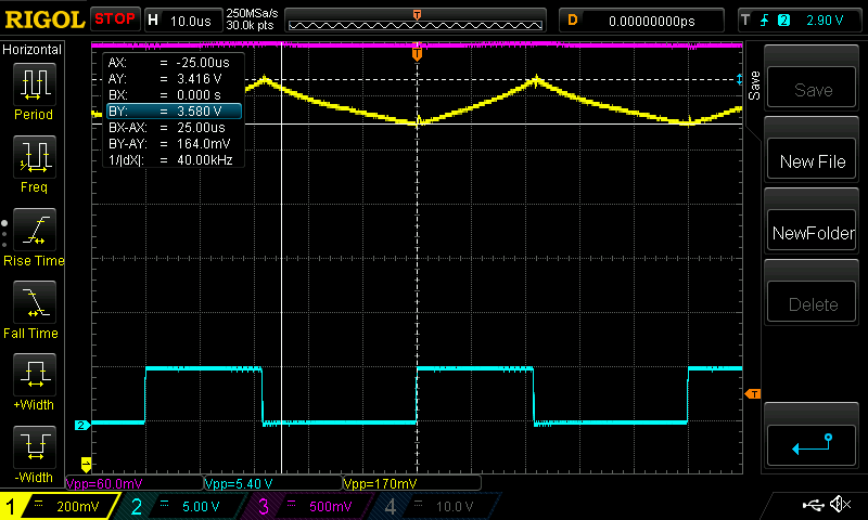 and here it is with 2.3kW, clearly showing signs of saturation. This is about 50 Amps. 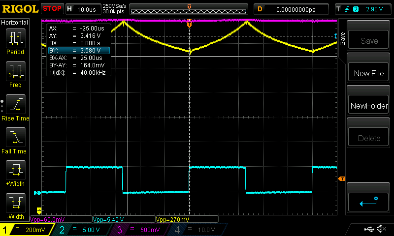 Again I call this a good candidate for the project. This test used the board with the 150V MOSFETS and so we get a little bit more efficiency and a bit less heat. I suspect the 100V HY5110 MOSFETS are exposed to voltages well in excess of the tested (by me) avalanche voltage of about 108V, and when they get these high voltages they just short it. The efficiency values I have provided here are guides to confirm we are on the right track. Every test so far has better than 92%. The tests are meant to show the inductor's behaviour under typical high power levels. We can then give them a pass or fail depending if they saturate too badly. Also the tests show the importance of using a reasonably high inductance value, to give the output filter caps a good chance of working for more than a year by keeping ripple current down to OK levels. wronger than a phone book full of wrong phone numbers |
||||
| Warpspeed Guru Joined: 09/08/2007 Location: AustraliaPosts: 4406 |
Fifty amps is really a bit much for it, thirty amps would probably be about the limit. Its clearly well into the onset of saturation, with rapidly diminishing inductance, and its going to get really hot. Still, its been an interesting comparative experiment. Two pairs of those "U" cores stacked, with about half the existing turns and thicker copper would get you back to 600uH and should be capable of perhaps sixty amps if you keep the same air gap. Its going to be pretty big, but then 2.5Kw continuous is serious power. Cheers, �Tony. |
||||
| nickskethisniks Guru Joined: 17/10/2017 Location: BelgiumPosts: 416 |
I found this one buy accident... Swinging E70 core And not even that expensive! Edited 2020-07-01 23:10 by nickskethisniks |
||||
| SYM-1 Newbie Joined: 18/10/2019 Location: New ZealandPosts: 40 |
Or this one with a 2mm gap https://www.semic.info/lj-e-6527-cf139-g-2-00-14/ Persistence is the key |
||||
| noneyabussiness Guru Joined: 31/07/2017 Location: AustraliaPosts: 506 |
OK, i need help.. please.. I've assembled one of the boards, and have obviously missed something. it will do a " soft start " every 30 odd seconds but that's it. i know the current sensor is working as i have been using this to test everything basic_pwm.zip and its responding happily... the only mods I've made outside of design is R6 is 470 ohms as i will eventually need it to accept closer to 200v if possible, which leads me to second change, K30T60 igbt's as main switching device. ill post some pics when i can, input voltages are 53v and output is a small vla battery and 2 250w 24v lamps.. as a load. this is a output of my settings : A - max heat sink temp 100 degC B - max inductor temp 150 degC 1 - Fan ON temp 50 degC 2 - Fan OFF temp 47 degC C - cal. Input Volts 0.5408 ( 53.00 V) D - cal. Output Volts 0.0133 ( 13.33 V) E - cal. Input Amps nan ( nan A) F - cal. Output Amps nan ( nan A) G - zero Iin sensor 119 ADC counts H - zero Iout sensor 118 ADC counts I - Max battery Volts 100.00 Volts J - Absorb voltage 61.00 Volts K - Absorb tolerence 0.30 Volts L - Maximum Current 500.00 Amps M - Night power 20.00 Watts N - Zero Energy total 0.00 kW.hr O - Equalisation voltage 63.00 Volts P - EQ duration 60.00 minutes Q - EQ reset tolerance 1.00 Volts R - Absorb duration 120.00 minutes S - Float voltage 59.00 Volts T - Float tolerence 0.50 Volts U - fast OC enable 0 (ON = 1, OFF = 0) V - pwm freq. 20 (20 or 40) Y - Calibrate mode 0 (1 = ON, 0 = OFF) Z - Write defaults no matter what i put in input / output amps they ether nan or inf, but i know both sensors are working.. oh the other change, both are 100amp models as its all i have. thank you in advance, sorry for my stupidity I think it works !! |
||||
