Notice. New forum software under development. It's going to miss a few functions and look a bit ugly for a while, but I'm working on it full time now as the old forum was too unstable. Couple days, all good. If you notice any issues, please contact me.
Murphy's friend Guru Joined: 04/10/2019 Location: AustraliaPosts: 584
Posted: 10:48am 11 Jul 2020
Copy link to clipboard
Print this post
Very neat idea, so simple. I used to make these type bobbins from phenolic sheet with interlocking sections, that was a lot more fiddly than your soldering idea.
A tip, rather than filing the edges round (not much roundness in 1.6mm BTW) why not visit your favored hardware store and look in the timber aisle for a suitable moulded Tassie Oak section with rounded sides or cut a big dowel in half lengthwise. As there is no space constraint at the ends of the bobbin the wire goes round much easier over that extra padding and the tiny bit of extra length makes no difference. Winding heavy gauge wire around too sharp a corner lifts it off *both* sides of the corner and you may need all the available space in the core slot. Winding around generous rounded ends does not lift the wire off the flat side.
nickskethisniks Guru Joined: 17/10/2017 Location: BelgiumPosts: 416
Posted: 01:18pm 11 Jul 2020
Copy link to clipboard
Print this post
Nice, would you sent to Belgium, although it could be cheaper to have them fabricated and sent from China.
It would also withstand higher temperatures then the 3D printed pla or abs bobbins I sometimes ask at a collegue of mine.
I now have some materials ( like the e65 ferrite, T200 iron dust, and iron laminated cores) collected for start testing @ higher input voltages, but forgot I don't have MOSFETs or diodes for higher voltages... I think I could use IGBT's laying around but I need to order other things so I will do that instead.
wiseguy Guru Joined: 21/06/2018 Location: AustraliaPosts: 999
Posted: 01:29pm 11 Jul 2020
Copy link to clipboard
Print this post
Winding heavy gauge wire around too sharp a corner lifts it off *both* sides of the corner
Murphy, I had the rounded idea (timber, plastic conduit section) in mind already. Klaus I believe suggested something similar to this in one of his threads.
I also imagined/wondered that by using thick wire it would try to do that rounded end naturally perhaps without needing a filler block. I would never have tried to hug the former closely on the narrow end.
Interesting that I never considered that it would lift on BOTH sides of the 90 degree bend (a bit like a see saw) and yet intuition to smooth off the leading edge would tend to counteract that effect which I had not consciously considered.
It would be nice to find a source of the old starter motor, wide flat varnished copper wire they used for the field winding - it would be perfect in this application.If at first you dont succeed, I suggest you avoid sky diving.... Cheers Mike
wiseguy Guru Joined: 21/06/2018 Location: AustraliaPosts: 999
Posted: 01:41pm 11 Jul 2020
Copy link to clipboard
Print this post
Nicks I will send you a set of parts as a free gift. You need to pm me your address. FYI the cost for airmail is $3.70 for 50g. A set weighs 40gm it is touch and go whether I can pack it into an envelope with lightweight packaging and stay under 50gm - Ill get them to weigh it before I lick a stamp and put it on the envelope lol.
the next size up is $8.30 for 125 grams - I'll just use two $3.70 envelopes and send it in 2 instalments. I hope one doesn't go astray as it would be a real bummer to get half a choke If at first you dont succeed, I suggest you avoid sky diving.... Cheers Mike
wiseguy Guru Joined: 21/06/2018 Location: AustraliaPosts: 999
Posted: 04:03pm 11 Jul 2020
Copy link to clipboard
Print this post
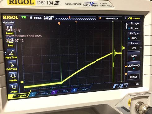
Ok I threw 12T on the former and placed 3 sets of E65 cores with a 1.6mm gap.
This is the scope pic. (current against time)
The shunt is 5mOhms Vert is 100mV/div and the time is 50uS/div, applied V is 30V.
so using v = L x di/dt - happy for someone to check my figures, its 1.30am and I'm falling asleep ....yawn so it may be all wrong.
I get 125uH and 720A turns and no sign of saturation yet.
The rest of the fun will have to wait until I get my mosfets and the MPPT board built up. Edited 2020-07-12 02:04 by wiseguyIf at first you dont succeed, I suggest you avoid sky diving.... Cheers Mike
Warpspeed Guru Joined: 09/08/2007 Location: AustraliaPosts: 4406
Posted: 08:32pm 11 Jul 2020
Copy link to clipboard
Print this post
Your figures look good Mike.
I have only just woken up, just having my very first cup of coffee, so my calibrated eyeball may not be seeing too straight yet.
5 milliohms and 100mV/div = 20 amps/div, and I am seeing 70 amps peak. Thirty volts, 320uS and 70 amps suggests 137uH
I like the rounded end turns idea, there is no need to hug the core. No need to crease the wire at the corners, which means the wire can be removed and replaced if needed with minimal damage.
SYM-1 Its entirely practical to use much thicker solid wire in a choke, as long as the ripple current is low enough. Its only the 6.6 amps of ripple that creates skin effect, and that small proportion of current can flow along the surface of the wire quite readily. The fifty or sixty amps of dc will flow through the entire wire cross section without any additional losses.
I suggest you try rewinding that monster with 10mm sq or 14mm sq plastic insulated fine stranded automotive cable, using the same 100 turns, or whatever turns will completely fill up the hole.Cheers, �Tony.
Warpspeed Guru Joined: 09/08/2007 Location: AustraliaPosts: 4406
Posted: 09:02pm 11 Jul 2020
Copy link to clipboard
Print this post
Any reasonably large transformer winding business will very likely have some left over short lengths, or whole drums or rectangular wire.
The smallest available size will be 3mm x 3mm and the more common sizes go up to about 3mm x 12mm. Its much more practical for very wide coil bobbins, but its a real bastard at the ends as the really wide stuff is difficult to bend sideways. � Also beware, some of this flat wire is aluminium not copper, the varnish colour makes it look like copper, but make absolutely certain of what you are getting.
I rather like the "Klaus" method of fitting as much copper into the available space as possible. The trick is to measure the width of your bobbin, and knowing the required number of turns, select a wire size that will fit the exact number of turns onto one full neat layer. Then just keep adding more layers until the bobbin is full. You cannot do any better than that with round wire. Edited 2020-07-12 07:06 by WarpspeedCheers, �Tony.
poida Guru Joined: 02/02/2017 Location: AustraliaPosts: 1389
Posted: 12:00am 12 Jul 2020
Copy link to clipboard
Print this post
This looks very neat, useful and probably work well. No saturation at 70A is great at 135uH and that means of course where do you source the needed copper to optimise DC I2R loss
I think we all are going have some fun with this project. (that was one of my aims in starting it)wronger than a phone book full of wrong phone numbers
SYM-1 Newbie Joined: 18/10/2019 Location: New ZealandPosts: 40
Posted: 12:10am 12 Jul 2020
Copy link to clipboard
Print this post
What is the advantage of the bigger wire? �We have the 4mm2 wire available and it is easy to wind. �Looking at limits - not necessarily my intentions - the 4 x AWG11 wire should be able to handle 90 Amps in free air. �At this current I have 180 watts to dissipate. What are the limitations of this core. �Do the ampere turns of 9000 scare it? �I only suggest this to fully understand the limitations. �620 watts is unacceptable and perhaps unsustainable losses. �What starts to happen at higher current flows? �I assume that I don�t really have a problem with maximum voltage and can easily go to 120V or even 150V at the cost of a bit of efficiency. Edited 2020-07-12 10:16 by SYM-1Persistence is the key
Warpspeed Guru Joined: 09/08/2007 Location: AustraliaPosts: 4406
Posted: 01:11am 12 Jul 2020
Copy link to clipboard
Print this post
Nine thousand ampere turns will be fine on a T520-2 core.
That is right at the end of the published curve (342 Orsteads) and there will still be 94% of the original inductance remaining at that point.
My wire table says AWG11 is 2.3mm diameter or 4.1mm sq as you say. One strand of that would be good for about 16 amps in a multi layer winding. One strand in free air more than that, 22 amps sounds entirely possible.
One metre length of one strand would be about 4.375 milliohms. At 16 amps that dissipates 1.12 watts. Four parallel strands at 64 amps would dissipate 4.48 watts.
I could not even begin to guess at the total length of wire in 100 turns, but its going to be quite a lot, and 4.48 watts per metre copper loss is going to add up.Cheers, �Tony.
Warpspeed Guru Joined: 09/08/2007 Location: AustraliaPosts: 4406
Posted: 01:19am 12 Jul 2020
Copy link to clipboard
Print this post
Its interesting how things go when there are several different people contributing ideas.Cheers, �Tony.
SYM-1 Newbie Joined: 18/10/2019 Location: New ZealandPosts: 40
Posted: 01:36am 12 Jul 2020
Copy link to clipboard
Print this post
About 168mm per turn. 16.8 meters, 89mOhm per hundred turns, 109 watts loss at 70A, 45 watts at 45 Amps. Losses 2.1% at 45A. Edited 2020-07-12 11:44 by SYM-1Persistence is the key
Warpspeed Guru Joined: 09/08/2007 Location: AustraliaPosts: 4406
Posted: 01:51am 12 Jul 2020
Copy link to clipboard
Print this post
It will go to 9,000 ampere turns without any problem, but its just starting to curl up its toes at that point. I might suggest that is the prudent dc limit.
Ac losses in the core are exceptionally low, this is a very high frequency material with very low core loss. Much higher frequencies will be no problem at all. As you go up in frequency, ripple current decreases, and skin effect will not become excessive or a problem either. Higher voltages just increase the ac flux swing, but our ac losses are very low anyway, so higher operating voltages will be no problem either.
Where we need to be more careful is copper loss, and the temperature rise that creates. The more copper area you can squeeze through that hole, the cooler it will run, and the more efficient it will be. That is what is going to set the limits with this particular core.
If you still need more, stack two cores. That will double the inductance per turn, but the 9,000 ampere turns limit still applies. But with two stacked cores you can then reduce the turns count and run thicker wire and still reach the target inductance.Cheers, �Tony.
SYM-1 Newbie Joined: 18/10/2019 Location: New ZealandPosts: 40
Posted: 03:57am 13 Jul 2020
Copy link to clipboard
Print this post
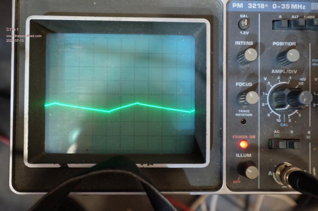
I have been working on measuring my inductance using the dv/dt method.
I have a T520-2 core. Well two stacked cores. They have 100 turns.
I performed my test running into a resistive load of 0.75Ohms. Now to calculate the inductance I needed:
Input Voltage = 72.8V Output Voltage = 17.4V uS rise time = 42uS Current Swing on output = 5.2A (4V/0.75Ohm)
((72.8 - 17.4)Volts*42uS/1,000,000/5.2Amps = 447.8 E-06 or 447uH
Now if this is true - I should be able to drop the number of turns down to 30 and use some 6mm tape or something similar to get the voltage drop down.
I guess the current swing will go up in proportion. I wonder how much the current swing effects the maximum power output of the panels.
4V swing (5.2A) 20 uS per div 5V per divPersistence is the key
Warpspeed Guru Joined: 09/08/2007 Location: AustraliaPosts: 4406
Posted: 06:15am 13 Jul 2020
Copy link to clipboard
Print this post
If you reduce the turns from 100 to 30, that is x 0.3 turns.
Inductance will change by 0.3 x 0.3 = .09
447uH will become 40.23uH
With a voltage difference across the choke of of 55.4v (72.8v - 17.4v) and an "on" time of 42uS the peak to peak ripple will now be 57.8 amps.
Why would you want to do that ?Cheers, �Tony.
SYM-1 Newbie Joined: 18/10/2019 Location: New ZealandPosts: 40
Posted: 10:00pm 13 Jul 2020
Copy link to clipboard
Print this post
It certainly helps to publish my intentions here. Even if it makes me look stupid. Thanks for your help. I wouldn't want to do that. I am still getting used to the inverse square relationship of the inductance to the turns. I was trying to work out a way to maximise the current without increasing the losses but I think I will aim more towards excellent operation at lower currents and loss of efficiency at high currents so I will work out what I can achieve with 6mm x 4mm tapes.
I quite like my higher inductance so here is my next proposal. I think I can get some tape. It is about 6mm x 4mm which would give me 24mm2. I can get about 108 turns on 3 layers and still leave 53mm to get my bobbin through. This is 24mOhm. At 2.3A per mm2 we get 55A. A power output of 2.6kW. I2R is 73Watts.
Alternatively I may only be able to get 4mm x 2.4mm tape. I can get 112 turns on 2 layers. But it is only 9.6mm2 so to achieve greater than 24mm2 I will need 6 layers leaving 48mm to get my bobbin through. 27.14m but 3 windings in parallel. I think that works out to 20.7mOhm (using the formula resistance = length*(22/CSA)) so that gives me 273 watts which seems a bit much. If I run current st 2.3A per mm2 I get 66A which gives me 90 Watts heat to dissipate and power output will be 3.1kWPersistence is the key
Warpspeed Guru Joined: 09/08/2007 Location: AustraliaPosts: 4406
Posted: 11:34pm 13 Jul 2020
Copy link to clipboard
Print this post
I would not be too concerned about the copper losses.
As you will know, that increases square law with current, so dropping from say 65 amps to 50 amps, a power decrease to 77%, reduces the conduction loss to 60%. If there is plenty of sun, and you are transferring perhaps a couple of kilowatts of dc power, fifty or seventy watts of loss is still a very small proportion.
It sounds like a lot, but that is a very large core with a very large winding on it, and the temperature rise will not be that high. Next time you take a photograph, put your hand or something else in the picture to give a size reference. �I think its going to surprise a lot of people here how large that toroid actually is.
When the sky is grey and horrible, and solar is greatly diminished, the copper losses will be negligible. Core losses will be constant, regardless of power transfer, but core loss are going to be extremely low with that dash two material.
Reducing the turns count would theoretically increase the ac flux swing �and core loss, but reduce copper loss. That is not a good trade off for this type of application.
The rule of thumb to design any choke with any type of core material is to first select an appropriate wire size, based on safe temperature rise at maximum load. Fit on as many turns as will possibly fit onto the core. Lastly, adjust the air gap (assuming there is one) for optimum inductance versus saturation threshold.
At these kinds of currents the wire is going to be pretty large, heavy, and very difficult to deal with. Solid copper is just not going to be practical, even Superman probably could not bend it Your best bet will be very fine stranded very flexible single insulated cable typically used for car starter motors and battery jumper cables. Welding cable is good too, but its usually double insulated, and the extra thickness of the insulation takes up valuable room.
One last random thought. Chinese cable is cheap, but the thermoplastic is often very thick, and of a soft grade that will just about melt in direct sunlight, so beware. Good quality automotive/marine or welding cable will survive years of high temperatures typical near the engines in cars and boats. Edited 2020-07-14 10:01 by WarpspeedCheers, �Tony.
Murphy's friend Guru Joined: 04/10/2019 Location: AustraliaPosts: 584
Posted: 09:56am 14 Jul 2020
Copy link to clipboard
Print this post
While you are pondering the theoretical side of heavy gauge wire I'll try to give you some practical advice. You will find 6x4mm wire requires a powerful machine, like a lathe if its a straight bobbin, to wind it. Forget doing that size by hand.
Your next choice, 4x2.4mm is just about doable by hand *and* plenty of soft faced hammer application. You will not be able to wind it very tightly around so allow extra room. The hardest part of winding this kind of wire by hand is at the start, you need to clamp the end *very* securely or it will just slip round and round the core. It gets easier after two or three turns - been there, done that
Warpspeed Guru Joined: 09/08/2007 Location: AustraliaPosts: 4406
Posted: 11:05am 14 Jul 2020
Copy link to clipboard
Print this post
Agree its going to be very difficult even on a powerful machine winding on an open bobbin. This is a powdered iron toroid. And its fragile. Use of force, beating on it with a rubber hammer and such, are quite out of the question.Cheers, �Tony.
SYM-1 Newbie Joined: 18/10/2019 Location: New ZealandPosts: 40