
|
|
Forum Index : Electronics : 150V 45A MPPT - roll your own
| Author | Message | ||||
renewableMark Guru Joined: 09/12/2017 Location: AustraliaPosts: 1678 |
Pete, I have been busy doing home school and still don't have all the bits. My brain is scrambled from having this kid at home driving me bonkers, I'm seriously finding it hard to function and think strait anymore. 5110 is this?yeah? Is 50A sensor this one? Or option 2 this one 100A sensor this one? Also what DC DC converter was decided on, I can't find it. Power supply is 5v for brain board and 12v for power board, do they need to be isolated? Cheers Caveman Mark Off grid eastern Melb |
||||
| poida Guru Joined: 02/02/2017 Location: AustraliaPosts: 1392 |
the 5110 is what you have selected from LCSC I would get a few extra, they are 100V equivalents of the HY4008 which are 80V of course. The 50A sensor you link to is a bipolar, it does negative as well as positive currents, all offset about the 2.5V output signal. This kills 1/2 of the sensitivity. I would use the unipolar type, only capable of positive current sensing. the Allegro part is ACS758LCB-050U and the LCSC link is here Note the "U" in the part number. U means unipolar. "B" in in the part number means bipolar. The power boards are correctly designed (of course!) and when you install the unipolar sensor, the current flows in the correct direction. So it is your "option 2" Do not bother with 100A sensors, we are not going there. The DC-DC converter I use to power the power board is based on the XL7015 or XL7056. Both can take 80V input. All we need is about 1 Amp at 12V output. Isolation is not needed, nor is it important. I use the XL7015 based little boards that give me 1A or a bit less. But anything that works for you will do. You must use a proper isolated 12-12 converter on the powerboard (marked U1 or U1A), or use an isolated 12V supply and just jank it in where it's outputs go. I have made 4 boards, 3 that use the 12-12 RECOM isolated converters, and one that uses a 240V AC to 12V isolated converter. The mppt converter that is running the East facing array is the one that uses the 240V-12V isolated converter. (I had run out of RECOM 12V-12V converters at that stage) So, 1 x battery voltage to 12V, to power the powerboard and then the brainboard AND 1 x 12V to 12V isolated converter or a offline 12V isolated supply of some sort. It must be isolated. Must. wronger than a phone book full of wrong phone numbers |
||||
| renewableMark Guru Joined: 09/12/2017 Location: AustraliaPosts: 1678 |
Thanks mate, is this one ok, is 3w enough? Cheers Caveman Mark Off grid eastern Melb |
||||
| wiseguy Guru Joined: 21/06/2018 Location: AustraliaPosts: 1017 |
Mark, 3W is definitely adequate and a good choice, 2W should also be ok but 1W is probably getting a bit light on in retrospect, over engineering is not always a bad thing. I'm glad I'm past the home schooling thing sheesh - you can have that ! Edited 2020-08-10 20:27 by wiseguy If at first you dont succeed, I suggest you avoid sky diving.... Cheers Mike |
||||
| renewableMark Guru Joined: 09/12/2017 Location: AustraliaPosts: 1678 |
Cheers mate (literally)! Funny thing is the little fella's work has really improved, having one on one teaching has helped him enormously. But jeez I hope they get things back in control and the schools can open again. It's been an eye opener, shows how just a bit of extra help at home makes an enormous improvement, I'll keep it up to some extent when he goes back. Cheers Caveman Mark Off grid eastern Melb |
||||
| nickskethisniks Guru Joined: 17/10/2017 Location: BelgiumPosts: 428 |
You need to check the footprint Mark, I don't know if it will fit. |
||||
| wiseguy Guru Joined: 21/06/2018 Location: AustraliaPosts: 1017 |
The board is designed to accept 3 foot print types, 2 x stretched types and the compact type that Mark asked about. Just install it as per the U1A silk screen outline. If at first you dont succeed, I suggest you avoid sky diving.... Cheers Mike |
||||
| renewableMark Guru Joined: 09/12/2017 Location: AustraliaPosts: 1678 |
I already ordered the RS type, but for others benefit.these would work too wouldn't they? Only 2w though Edited 2020-08-11 07:57 by renewableMark Cheers Caveman Mark Off grid eastern Melb |
||||
| renewableMark Guru Joined: 09/12/2017 Location: AustraliaPosts: 1678 |
Just need to confirm something, does the brainboard get power from the power board or does it need it's own 5v supply? Cheers Caveman Mark Off grid eastern Melb |
||||
| poida Guru Joined: 02/02/2017 Location: AustraliaPosts: 1392 |
The brainboard gets 12V from the power board, and from this, makes the 5V needed to run the LCD and Nano. wronger than a phone book full of wrong phone numbers |
||||
| renewableMark Guru Joined: 09/12/2017 Location: AustraliaPosts: 1678 |
Can I use fod 3120 instead of tlp250? I have heaps of them, pinout looks the same. http://www.kosmodrom.com.ua/pdf/FOD3120.pdf file:///C:/Users/admin/Downloads/datasheet_en_20190617.pdf Cheers Caveman Mark Off grid eastern Melb |
||||
| Warpspeed Guru Joined: 09/08/2007 Location: AustraliaPosts: 4406 |
Mark, FOD3120 works with supply from +15v to +30v TLP250 works from +10v to +35v If you have +15v supply, either will do, if only +12v, must be a TLP250 Cheers, �Tony. |
||||
| renewableMark Guru Joined: 09/12/2017 Location: AustraliaPosts: 1678 |
Thanks Tony, I found some fod 3182 as well. https://www.mouser.com/datasheet/2/149/FOD3182-93828.pdf Cheers Caveman Mark Off grid eastern Melb |
||||
| wiseguy Guru Joined: 21/06/2018 Location: AustraliaPosts: 1017 |
If you want a better FET drive IC, that operates from 10V up, the FOD3180 - or yes FOD3182 is a good way to go, it has a minimum output of 2A/3A drive. �Output is FET not bipolar. A word of caution, the FOD3180/FOD3182 will operate at up to 250kHz versus 25kHz for the TLP250 so if planning to try higher switching frequencies don't use the TLP250 unless you intend to use around 20kHz only. Mark the 2W unit you linked to is a -12V, 0, +12V converter -I don't recommend it - if you want to use one, then cutting off pin4 (closest pin to the end 2 pins) �& ensuring the stub left wont touch the pcb pad when installed it should work. �A single output type will be the best type to use. Edited 2020-08-11 14:42 by wiseguy If at first you dont succeed, I suggest you avoid sky diving.... Cheers Mike |
||||
| renewableMark Guru Joined: 09/12/2017 Location: AustraliaPosts: 1678 |
Thanks mate Edit, jeez, just found some 3210 as well. Edited 2020-08-11 15:19 by renewableMark Cheers Caveman Mark Off grid eastern Melb |
||||
| renewableMark Guru Joined: 09/12/2017 Location: AustraliaPosts: 1678 |
Turns out I have most parts, I ordered the current sensors from RS as they weren't much dearer and will be quicker. All I'll be waiting a long time for is the 5110. So since they are just being used for a diode which one from this selection will work (with plenty of leeway) Cheers Caveman Mark Off grid eastern Melb |
||||
| wiseguy Guru Joined: 21/06/2018 Location: AustraliaPosts: 1017 |
Personally Mark I would be reluctant to use a FET in stead of a lower diode in the MPPT. I dont argue against Poidas work and results but I would expect to get improved (maybe only marginal) results using a conventional diode approach. My preferred type of diode should be a HV Schottky the STPS40H100CW type in your list is a good choice for 100V inputs, for 150V the STPS61150CW type in your list is fine. Although 1 x TO247 dual diode will suffice you will save a few watts of heat by putting two in parallel. My second choice, if you dont mind quite a few extra (wasted) watts is the ultrafast series of diodes such as U30D20 or the MUR3020WTG from your list. They are rugged and work well, if you have them to hand, but they will run hotter than the suggested schottkys. You must use 2 of these ultrafast TO247 types as they are a bit light on for 40A output. I have not constructed my Power PCB for the MPPT and run any tests yet so will with hold on making too many suggestions or comments until then, I have had a lot going on lately to distract me from what I would prefer to be doing! Edited 2020-08-11 16:35 by wiseguy If at first you dont succeed, I suggest you avoid sky diving.... Cheers Mike |
||||
| noneyabussiness Guru Joined: 31/07/2017 Location: AustraliaPosts: 506 |
The tlp350 runs up to 50khz... and pin for pin compatible to tlp250 I think it works !! |
||||
| wiseguy Guru Joined: 21/06/2018 Location: AustraliaPosts: 1017 |
A reminder, if using the FOD3180/3182 optos the series resistor (R1) should be no higher than 330R and I suggest to use 270R as a minimum. The performance of the optos are guaranteed for LED currents of 10 - 16mA. using the worst case data from the spec sheet, 330R gives ~ 9.7mA whilst 270R gives ~ 11.8mA. If using the TLP250/350 I would recommend no higher than 470R which yields ~ 6.8mA just a tad under their range of 7-10mA recommended operating conditions. Edited 2020-08-12 00:32 by wiseguy If at first you dont succeed, I suggest you avoid sky diving.... Cheers Mike |
||||
| poida Guru Joined: 02/02/2017 Location: AustraliaPosts: 1392 |
here is the latest code. No 3rd party libraries are needed. It uses the serial data LCD. mpptv5.zip Here is how the heat sink temperature controls the output current as 55C is exceeded. This test was at 1720W output. Purple is temperature. Red is Vout Yellow Iout Green Iin Blue Vin The setting is 55C to start output current reduction, with a maximum temp of 65C So each degree above 55 will take 10% of maximum output current. It works well I think. It flattened the rate of rise of the Purple curve which is temperature of course. (in other news, the prototype mppt has just achieved the 100kWhr landmark for output) 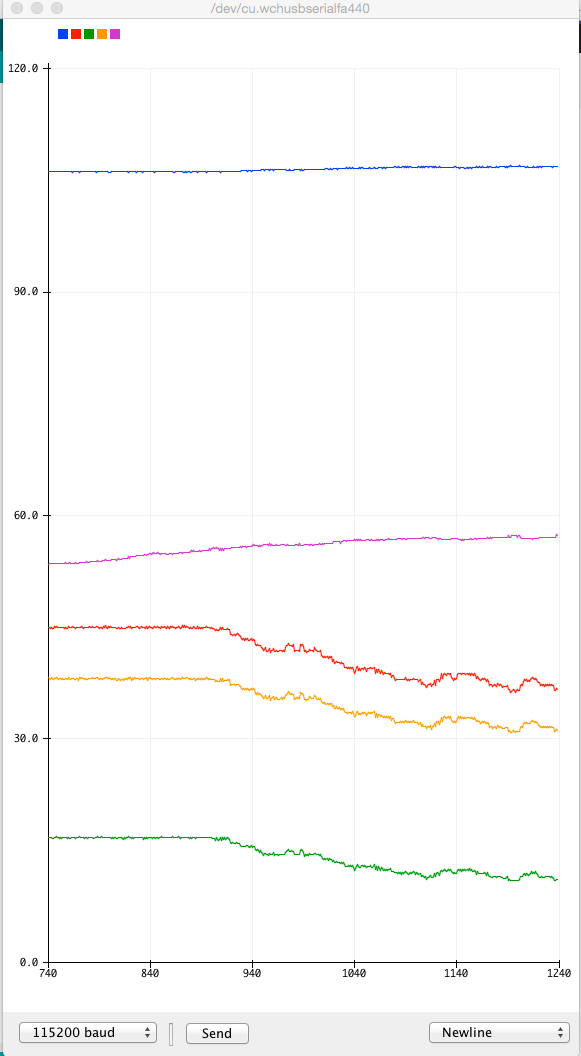 wronger than a phone book full of wrong phone numbers |
||||
