
|
|
Forum Index : Electronics : 150V 45A MPPT - roll your own
| Author | Message | ||||
| poida Guru Joined: 02/02/2017 Location: AustraliaPosts: 1389 |
When working with a toroid shape core (and not an E core) one turn is counted for each pass through the middle hole. I would not worry if the readings are a bit different. I gather you are using the same core as I did. We need about 100uH to keep the peak to peak current ripple low enough to be comfortable with the build. More is fine. Less is OK too. LCR meters can give differing results when checking the choke with different meter test frequencies. And there are 2 ways of measuring them. "parallel" and "series". These 2 ways also give different values. Results using the BK Preceision 879B LCR meter and a nice "100uH" E core with about 9 turns (it could be 9 1/2 turns..) "Series": tested at 100Hz, its 100uH at 1kHz, its 99.5uH 10kHz, its 99.38uH "Parallel" 100Hz, its 737uH 1kHz, its 106uH 10kHz, its 99.45uH There is a huge difference with Parallel mode measurement at 100Hz. I don't know what mode the POS meter of yours is using. Probably the default my meter uses which is Series. wronger than a phone book full of wrong phone numbers |
||||
| Warpspeed Guru Joined: 09/08/2007 Location: AustraliaPosts: 4406 |
And don't forget that exact the air gap has an effect. Even a fraction of a millimeter can make rather a difference to the actual numbers. And Peter is quite right, the measurement frequency has a significant effect as well. You are not just measuring a pure inductance, there is no such thing! Every physical coil has some distributed capacitance, and therefore a self resonance at some(?) frequency. The closer you get to the self resonant frequency, the more crazy and unbelievable the readings can become. Every inductance meter has to use "some" frequency to make the measurement, and that can vary widely between instruments. So don't be too surprised if different instruments tell you some very different and sometimes rather disturbing things. The best indication of all, is to just fire the damned thing up in the circuit it is supposed to work in, and measure the triangular ripple current. That is basically the bottom line, and proof of working. Cheers, �Tony. |
||||
renewableMark Guru Joined: 09/12/2017 Location: AustraliaPosts: 1678 |
Thanks fellas. I'll have to work out that test procedure now. Edited 2020-12-01 17:36 by renewableMark Cheers Caveman Mark Off grid eastern Melb |
||||
| poida Guru Joined: 02/02/2017 Location: AustraliaPosts: 1389 |
latest test code. IT needs a serial LCD on the 4 pin connector on left of the nano. First 3 pins go to the serial LCD. Ground, 5V and data (transmit from nano to serial LCD) The 4th pin is used to set the output voltage. You need to have some sort of load on the output. Something that can handle maybe 50V and a good few amps. Put about 2 or 3 headlight globes in series or something. I use enough thin wire wrapped around a bit of pine board, submerged in a bucket of water. This can take 3kW with ease. buck_converter_nics_1_b4_nano_pwmserial_bb.ino.zip start it up with near zero output voltage as set by the pot. Then wind it up to increase output voltage. IT will stop working if output voltage setting from the pot is greater than the input voltage. Edited 2020-12-02 15:35 by poida wronger than a phone book full of wrong phone numbers |
||||
| ryanm Senior Member Joined: 25/09/2015 Location: AustraliaPosts: 191 |
I've got some boards for this project and I'm looking to build it over Xmas. Does anyone have a list of the current best parts to order? Don't want to order FETs and diodes from page 1 and find out on page 30 of the thread that there's a better substitution. Any help much appreciated. |
||||
| poida Guru Joined: 02/02/2017 Location: AustraliaPosts: 1389 |
Ryanm: pretty much no changes are needed. The basics are the caps and resistors etc. The FETS are still the 150V type in the parts list. I prefer the FDH055N15A FETS since they are 150V and work well. Diodes can be 150V or 200V or more dual types in TO-247 package or use HY5110 FETs as diodes which is what I do. I have come to the point where I very much prefer using TTL serial data to communicate with the LCD. I find I2C interface to be quite susceptible to EMI and that it can lock up the nano in some cases. TTL serial data via softwareserial library or in the current firmware's case, fully synthesised 9600 baud TTL data is reliable as brick sh#thouse and just as tough. The large caps can be nearly anything. The Aliexpress sourced 100V 10,000uF caps do not like 105V or more and get hot and bothered. Combinations I have tried that work fine: 5 of 450V caps at 470uF or whatever on the input. And one 100V 10,000uF cap on the output and about 9 x 450V 450uF in input and 5 x 450V 470uF on output. and mixed 470uF or 540uF 450V on both input and output. We need a good amount of good quality caps that can handle some ripple. I tested a board with minimal input caps. With 3 only 450V 470uF caps on the input, these 3 caps got warm to the touch after a few minutes of 1kW+ work. Using only 1 x 100V 10,000uF Aliexpress Chinesium cap on the output was fine and that cap never got warm. Always the control loop was stable and the program worked perfectly. wronger than a phone book full of wrong phone numbers |
||||
| ryanm Senior Member Joined: 25/09/2015 Location: AustraliaPosts: 191 |
Thanks poida. With the length of some of these threads it takes longer to read than putting together the project. |
||||
| poida Guru Joined: 02/02/2017 Location: AustraliaPosts: 1389 |
for sure, it's about a 3 hour job to build a board. But the thread gives enough background to have some confidence, for me at least. One more thing: the input voltage divider needs 1K and 47K, not 2.7K and 47K if you use more than 90V input voltages. This change to 1K permits the measurement of 240V. If you use 2.7K, the measurement is limited to 92V. wronger than a phone book full of wrong phone numbers |
||||
| poida Guru Joined: 02/02/2017 Location: AustraliaPosts: 1389 |
I found the ideal enclosure for a mppt build. But it's pretty much rocking horse poo. I have only the one. 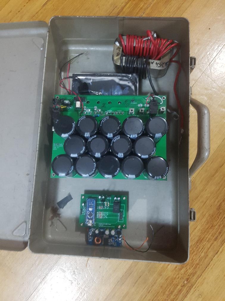 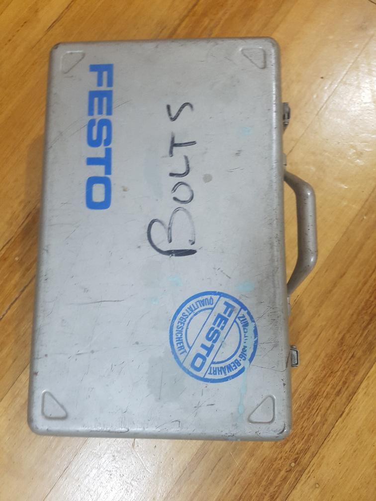 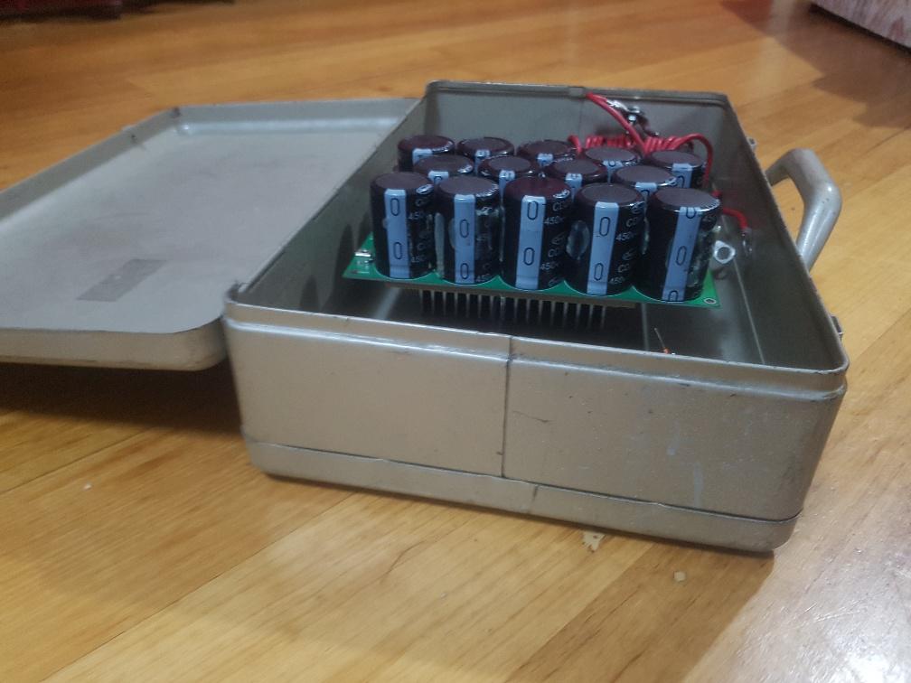 perfect size, with a front door on a hinge for easy access and nice latches. and by the way, the working mppt has got to 645kW.hr 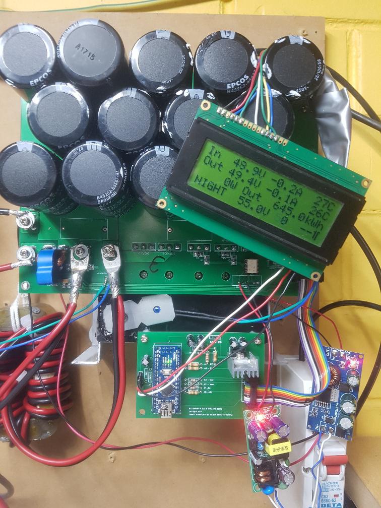 wronger than a phone book full of wrong phone numbers |
||||
| renewableMark Guru Joined: 09/12/2017 Location: AustraliaPosts: 1678 |
Peter, WTF gauge wire have you used on that choke? It looks very thin. The one in the box is different to the last pic you posted, that's just a test one right? Edited 2020-12-17 21:08 by renewableMark Cheers Caveman Mark Off grid eastern Melb |
||||
| poida Guru Joined: 02/02/2017 Location: AustraliaPosts: 1389 |
2 x 4.5mm2 It does not get too hot when running at 2kW I've seen 38C, never 50 or 60C I should be using something bigger but I seem to get away with murder sometimes so if I can, I will. The cable is the so called "6mm2 solar" cable sold on ebay. It has a thin black cover for both Red and Black conductors. I strip that and use the inner cable. It seems I get a very good copper area for the overall diameter. And the PVC is much more heat resistant than the crap I got from Jaycar as seen https://www.thebackshed.com/forum/ViewTopic.php?FID=4&TID=12773 I have enough space to run 3x but 2x is enough for this with the big laminated core. Edited 2020-12-17 21:14 by poida wronger than a phone book full of wrong phone numbers |
||||
| poida Guru Joined: 02/02/2017 Location: AustraliaPosts: 1389 |
The one in the box is just a test choke. I used whatever cable I had to make enough turns to get to a useful test value of inductance. I think I will use that core, but probably put 3 in hand windings through it of that 4.5mm2 cable to get to about 100uH. The choke in the picture with the box is 254uH so there is some room to wind up something nice with a core this size. wronger than a phone book full of wrong phone numbers |
||||
Revlac Guru Joined: 31/12/2016 Location: AustraliaPosts: 961 |
That will do the job, room for air vent's too, the LCD could cut into the door.  Cheers Aaron Off The Grid |
||||
| renewableMark Guru Joined: 09/12/2017 Location: AustraliaPosts: 1678 |
 Cheers Caveman Mark Off grid eastern Melb |
||||
| Warpspeed Guru Joined: 09/08/2007 Location: AustraliaPosts: 4406 |
Great stuff Peter Cheers, �Tony. |
||||
| nickskethisniks Guru Joined: 17/10/2017 Location: BelgiumPosts: 416 |
Hi all, The new brainbord ( Poida�s pcb) of my mppt controller is doing great! And is approaching the 200kWh mark. So, I started a new project (more on that later) and I was doing some research/experiments with gate drivers/mosfets,.. I tried more then 10 different mosfets with some different gate resistors in a buck converter testing rig. 30V 3A in , 14V 6A out. And each time I�ve got different results in the gate turn on and turn of curve. �When using for example 10R turn off and 20R turn on resistors I had some gate ringing around the miller plateau. And a rather strange turn off curve near the end. Choosing higher gate resistors helped reducing the ringing/oscillations. Ferrite beads were not helping most of the time, I only had 1 type. Adding gate/source capacitance like 4n7 was helping significant. I had the feeling that the higher (voltage) the mosfet was rated the better the curves were. I�ve tested IXFH110N25T, IRFP4110, IRFP4468, IRFP4668, IRFP4868, HY4008, IRFP064, RFG75n05, STP15810, IRFP150 Even IGBT�s, some salvaged Ixys parts I also tested a lot of diodes: RURG3020C,STTH6003, STTH6002,VS-60APU02-N3, 30CPQ100, 30CPQ150, MUR3020, 16CTQ100 Most impressed I was about the combination IXFH110N25T and the 30CPQ100, the ixys had little small oscillation around the miller plateau and a straight turn off line I never saw with the other mosfets I�ve tested. With the 30CPQ100 there was 15V shoot thru, the 60apu02 came close. The rest was around 20V, a ferrite bead helped at least 5V. But then there was more ringing during the turnoff� So even for an old part like the 30CPQ100, it actually gave the best curves... The igbt�s also impressed me a lot, they actually gave the best results, such nice turn on and off curves!!! But they produced lots of heat as well� All the irf parts were oscillating as hell. I must say it was just a small (though verry time consuming...)at only 100W... But then I was wondering, how were my curves on my mppt controller mosfets? And then I thought I never probed my second parallel mosfet in my mppt controller. Did you probed the second mosfet, Peter? I saw pictures with your probes soldered on to the pcb, but if you would retest and had soldered your probes on the mosfet itself you would have had even better curves! I noticed some serious difference between the 2 parallel mosfets, I�ve made a testing rig with my new pcb and with pcb terminals so I could easily swap mosfets and diodes out, and I noticed the length of the mosfet legs matter a lot. If I probe close to the mosfet things look already much better. I�m using probes with a 1cm stiff wire soldered to it. These are pictures from my scoop on the mppt controller, I used 12R gate resistors, IRPF4110 mosfets and apparently more then 15V gate voltage. I think it was doing around 60A. In my next pcb layouts I will place the drivers as close as possible and more symmetrical. These are my results: First mosfet closest to the driver: 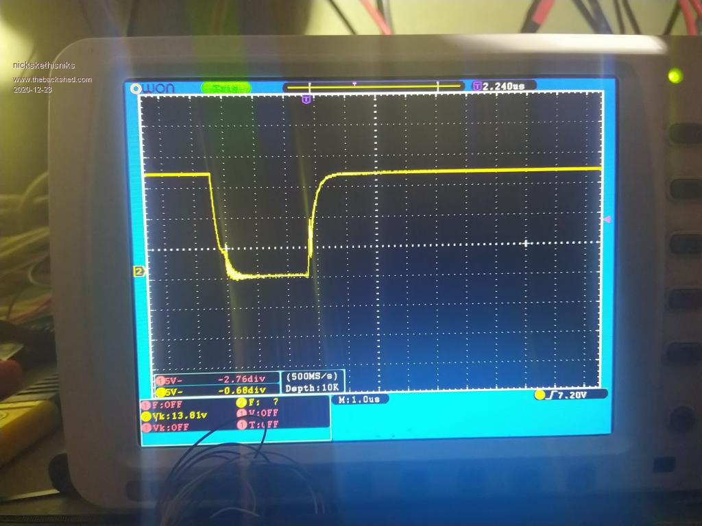 Second mosfet: 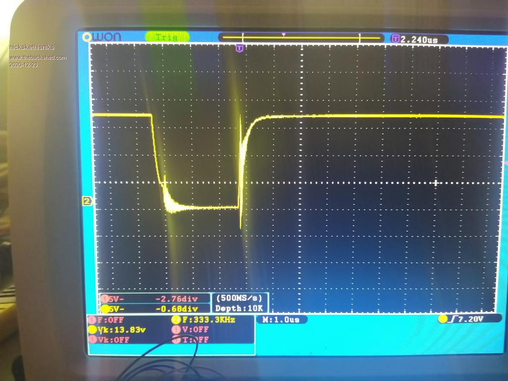 Edited 2020-12-23 07:07 by nickskethisniks |
||||
| poida Guru Joined: 02/02/2017 Location: AustraliaPosts: 1389 |
Nicks: this is interesting. I am using one of your boards as my test mppt board on the workbench. I am open to the suggestion that the MOSFETs can behave differently and can be shown to be different when you probe them. If I was doing this I would ensure identical ground connections for both MOSFET's probes. Even 50mm long ground wire is a "too long inductor" ground wire. It's probable you have good probe technique already here. My best combination is HY5110 MOSFETS used as diodes and the Fairchild FDH055N15A 150V MOSFETS as MOSFETS. Here is what I see on the switch node (the point where the MOSFET's SOURCE is connected to one of the leads of the inductor. Blue is switch node. Yellow is gate drive out of the nano into the TLP250 105V input, 48V out at 41 Amps (2000W approx.) I used the same horizontal timebase setting of 1uS/div switch ON: 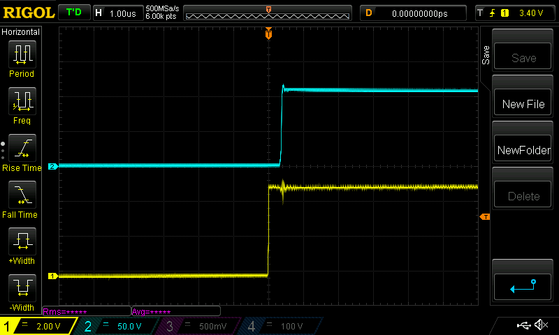 and OFF: 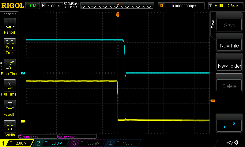 how I probe the Blue trace. This is good probe technique. Very low inductance earth lead. 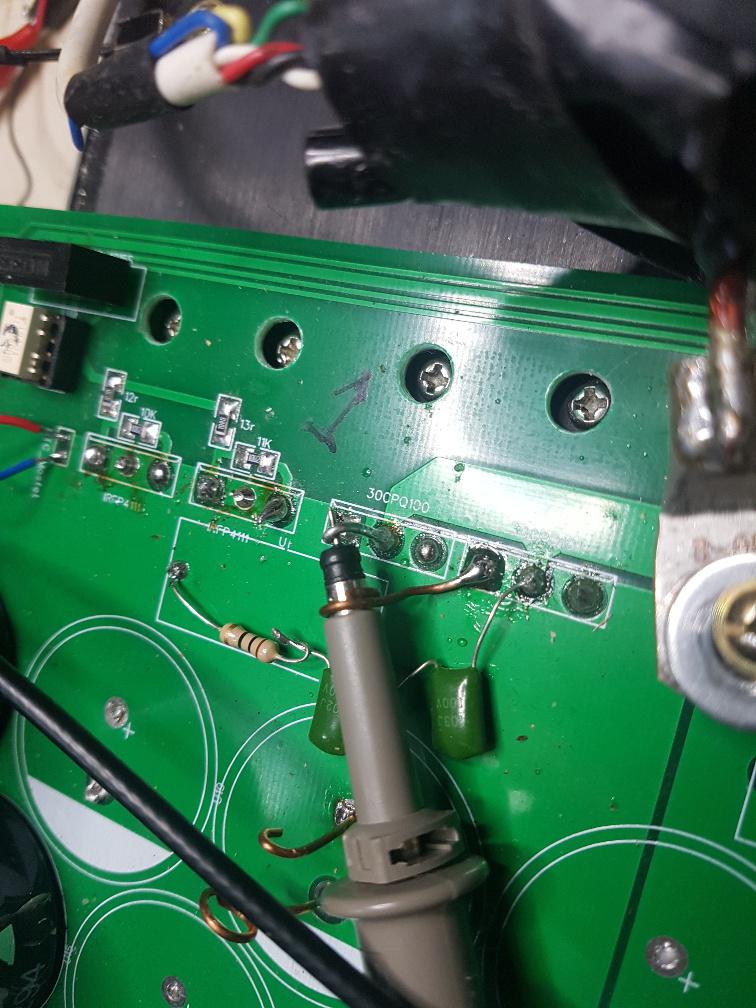 This probe location on the PCB lets me use DC ground as ground. That sounds a bit silly but it's a nice low impedance ground location to connect the DSO probe ground to. No ringing at all. I have a small RC snubber on the switch node to ground. You can see it underneath the probe in the above photo. 10R and a 102 and 103 cap in series. It just seems to work well. (2 caps in series? I must be on drugs. so it's likely a 10R and 103 cap in reality) edit: NO. its 909pf or a little less than 103 on it's own Edited 2020-12-23 22:24 by poida wronger than a phone book full of wrong phone numbers |
||||
| Revlac Guru Joined: 31/12/2016 Location: AustraliaPosts: 961 |
Nicks, Is that scope an OWON? looks good. Cheers Aaron Off The Grid |
||||
| nickskethisniks Guru Joined: 17/10/2017 Location: BelgiumPosts: 416 |
Yes that is, I like it's big screen a lot. I'm used to work with tektronix at work so there is a quality difference. But the owon is good value for the money and more than good for what I'm doing. I'm using SDS7072 which can also work on a battery, but I was on a budget 8-10y ago so didn't order it, but I can think I can hack that part now  . I will switch to a 4 chanel scoop in the coming years, sometimes I mis an extra input. And maybe an differential probe. . I will switch to a 4 chanel scoop in the coming years, sometimes I mis an extra input. And maybe an differential probe.It was used for 5years in a not heated shed so it had a rough life temperature and moist, the potmeters/encoders for Volts/div and sec/div need to be changed. Sometimes if I want to adjust the timebase or amplitude it goes the other way around. This is what I use for testing gate signals: 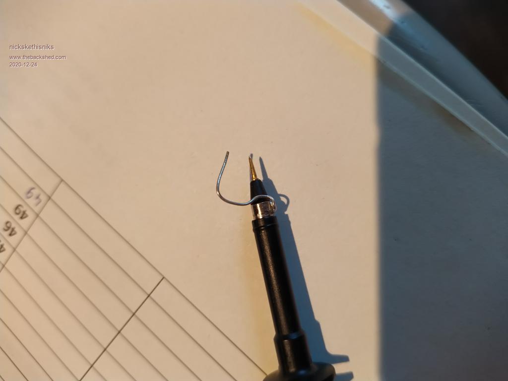 Peter I would like to see your gates/source signal, but you don't need to. I'm just looking for improvements that can be made in my next designs, it's allways a trade of between lots of things .In a next order I will try to order that mosfet you are using just to compare .I will try testing the switch node, but it's a clouded day (200watts...)for this moment so probably not much interesting to see on the scope. I'm sure this signal looks much better than what I see on my mosfets gates. Edited 2020-12-24 20:46 by nickskethisniks |
||||
| poida Guru Joined: 02/02/2017 Location: AustraliaPosts: 1389 |
Nicks: since the SOURCE of the MOSFETs is at either input voltage or output voltage, we can not connect it to DC supply ground. Which is also DC output ground. Which is also 12V supply ground. When probing the gate voltages of the two MOSFETs the probe "ground" is DC+ supply or DC+ output so I use an isolated probe. I don't want to float the scope since I am certain I will make a mistake and be needing a new DSO. here is the left hand MOSFET gate voltage and the TLP250 input. I use the same timebase as you have 1uS/div 105V in, 2050W out at 40 Amps roughly. It looks just like yours. Pink is TLP250 input Light Blue is gate drive. I use the 12V isolated dc-dc supply 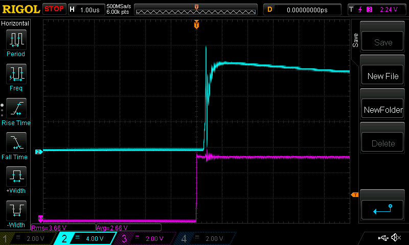 The differential probe does have good bandwidth suitable for 100nS/div so here is the same thing at this timebase. Dark Blue is the switch node voltage which swings from 0 to 110V The diff. probe inserts a delay of about 14nS so bring the Dark Blue trace to the left about that to line things up - not that it makes much difference. 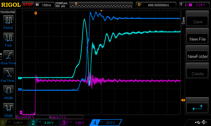 Having MOSFETS connected via their SOURCE pins to voltage swings of 0 to 110V rising in less than 100 nS puts a lot of strain on the floating 12V supply, TLP250 output stage, and pcb traces connecting all that and the MOSFET's GATE and SOURCE pins. The whole lot needs to swing up to 110V and do it quickly. I do not know what is real and what is caused by the huge common mode voltage swings. I recorded both left and right side MOSFET gate voltages using this timebase. One is above the other. They look the same but it's hard to see differences in voltage. 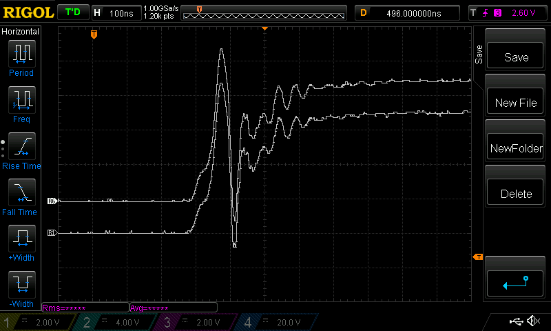 Now I put one on top of the other, using identical probe setup (which inserts identical spurious noise signals too) and they appear identical. I suspect that when you rework the PCB you will not obtain any improvement in reducing the gate drive differences since to me there is none at all. 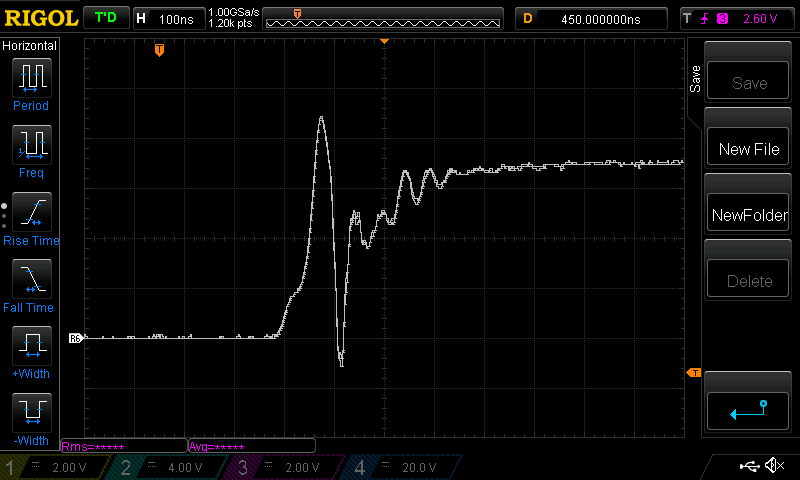 Edited 2020-12-25 16:01 by poida wronger than a phone book full of wrong phone numbers |
||||
