
|
|
Forum Index : Electronics : 150V 45A MPPT - roll your own
| Author | Message | ||||
| Murphy's friend Guru Joined: 04/10/2019 Location: AustraliaPosts: 584 |
It looks as if I have a question already  , I found this display panel; , I found this display panel;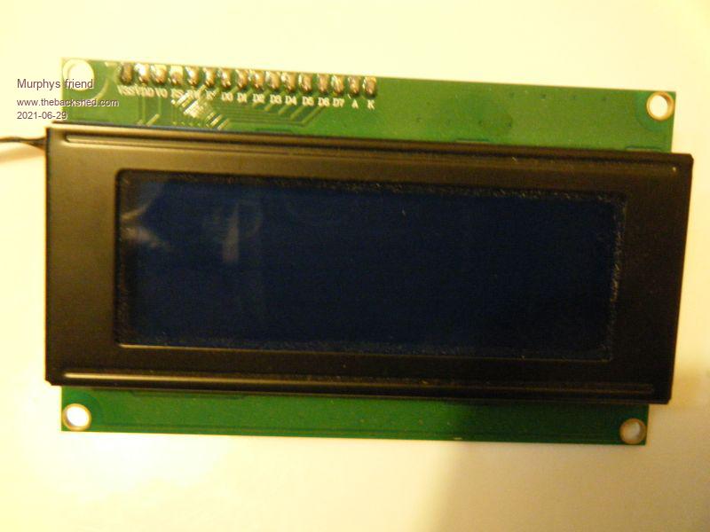 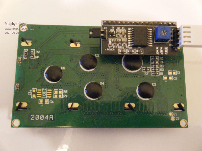 It looks as if it has that required serial port on the little piggy back PCB, would this be suitable for the home brew MPPT project? |
||||
| poida Guru Joined: 02/02/2017 Location: AustraliaPosts: 1389 |
It has the I2C port. 4 wires, 5V, GND, clock and data. It is easy to connect this LCD to yet another nano, program it and then connect the nano to both the LCD and the mppt. Why go this way with extra nano? I find the I2C bus to be very sensitive to EMI and this can upset the smooth running of the mppt firmware. I have tried using I2C direct from LCD such as yours to the mppt. The EMI from the choke is quite intense and it stuffs things up. This was the case with the last mppt I built, with it all inside the Festo jigsaw metal carry case. Your build might be OK with I2C. Who knows. I sorted it out permanently with the nano/LCD communicating with the mppt with the 3 wires going through a mains clip-on choke 2 turns. The 3 wires are 5V, ground and data (for serial data, 9600 baud, 8 bits, 1 stop bit no parity) Earlier in this long thread I posted the LCD nano code. There are two versions, depending on what LCD you have got. Some people have LCDs without the little I2C board attached and so we communicate directly with the LCD controller chip. Others have the LCD as you have, with the I2C module. So there are two different programs for the nano/LCD assembly. I go to all this trouble to end up with 3 wires connecting the mppt and the LCD. The wire lengths are quite long, maybe 8 inches or more. I want to have the wire leading into the mppt nano going to a more EMI resistant pin, to be setup as a digital output pin. This means the EMI has to pass back through the pin's output stage and then into the microcontroller chip's guts. And this is a lot harder for the weak current of the EMI. wronger than a phone book full of wrong phone numbers |
||||
| Murphy's friend Guru Joined: 04/10/2019 Location: AustraliaPosts: 584 |
Thanks poida. I'm good at building things but when it comes to program a nano or LCD (didn't know they need to be programmed too  ) I'm completely lost and seek your experience. ) I'm completely lost and seek your experience.So, if I make a brainboard, fit it into a shielded case with the LCD board in a window. Include a 12V to 5V Dc/Dc supply, this case then needs 12V input terminals and shielded wires to sample Vin, Iin, Vout, Iout and NTC plus terminals for the PWM drive and it should work? The power board will be separate close by and I have a choke (ex aero) with 23 turns of 15mmsq wire, 380uH and sat at 1500A/t. |
||||
| nickskethisniks Guru Joined: 17/10/2017 Location: BelgiumPosts: 416 |
For the EMI problems you want to try pull up resistors on both ends of the i2c bus. Use equal length of wires and to use maybe 2 shielded wires, 1 for the sda and gnd and 1 for scl and gnd. You don't want to have crosstalk between sda and scl. You want a good return path for the scl and SDA lines, so a good coupling with the ground (gnd). Instead of the shielded wires, you can also use 2 twisted pairs. Didn't tried it myself but I think this should/could solve the issue. A ferrite bead is most of the time a bandage to solve bad design, and more used in the latest stage of the design. I could be wrong but is a ferrite not more used to reduce radiation of the wire itself? Maybe the LCD and chip are also sensitive for EMI. I use the extra nano trick poida suggested. Anyone tried to shield the inductor? Or used some RM or P type ferrite core? It's also important to hold the 2 wires of the inductor close to eachother, and split them up close to the connector on the pcb. Edited 2021-06-30 06:45 by nickskethisniks |
||||
Revlac Guru Joined: 31/12/2016 Location: AustraliaPosts: 961 |
I have had good results using shielded PS2 Keyboard cable for the LCD on the Mad control board, the shield was wired to ground of the control board, not the LCD end. I haven't completed this charge controller yet, waiting for the DC converter and need to wind the choke, the rest of it is mostly done, will post a picture then. Cheers Aaron Off The Grid |
||||
| nickskethisniks Guru Joined: 17/10/2017 Location: BelgiumPosts: 416 |
I was wrong, a ferrite bead will help also to make it more immune... |
||||
| Murphy's friend Guru Joined: 04/10/2019 Location: AustraliaPosts: 584 |
Thanks nickskethisniks, I know you are being helpful but its like as if you are talking in a different language to this programming challenged person. For example, the many acronyms programmers are so fond of using are nothing but a mystery to me. If I cannot find a similar mention on the schematic, showing just where that particular signal is, I'm lost. So I have no idea what sda or scl stands for, sorry. Can you explain please? I like building electronic things but when they require a nano to program in order to work, that is a major hurdle for me. What I would like to do is to lay out a MPPT brainboard PCB with the same footprint than my LC Display panel so they can be piggy backed on spacers. I need to know if the extra nano poida mentioned to 'program' my above shown display panel is a permanent or temporary affair. So, one or two nano's for this project? If I can get the PCB's and all required connections sorted out first I can find somebody to do the programming bit for me if this proves to be to big a challenge. Oh I'm trying to fit this into a commercially available case, that's why I use my own PCB's. |
||||
| poida Guru Joined: 02/02/2017 Location: AustraliaPosts: 1389 |
Murph, it's a piece of piss. get a nano, program it with this nano_serial_to_i2c_LCD.ino.zip connect it to the I2C LCD you have. 4 wires, 5V, GND, CLK and DATA The Nano I2C clock is pin A5, data is pin A4. after programming, when it reboots you get a message "yada, yada, 9600 baud etc.." good. find 5V pin on that Nano, run a wire from it. Find GND, run a wire from it Find D10, run a wire from it, this is serial data IN for this Nano. So there are 3 wires. These 3 are hooked up to 3 of the pins of the 4 pin connector of the brainboard. But you will make your own PCB. Great! The mppt firmware outputs serial data via pin A4. Only 3 wires. connect A4 of the brainboard equivalent (you will be designing) to pin D10 on the Nano that is hooked up to the i2C LCD. And 5V and GND. There are a few reasons I like going this way. 1 - low EMI fed back into the mppt Nano. Pin D10 is set as digital input and much more robust. 2 - ZERO and I mean 1/2 of f%ck-all overhead from sending the serial data. 3 - NO F^CKING LIBRARIES ARE USED. This is important. Most libraries in the Arduino system use interrupts and other things that can interfere with YOUR/MY code. The mppt code such as mpptv5_BV_tempco.zip which is the code I run on both of my mppt controllers runs like clockwork when we use the serial data coming out of pin A4 of the Nano on the brainboard. It has not stopped or failed ever. So I now require this. That is to say I support anybody who builds using it. And I want to discourage use of I2C on the brainboard Nano. I2C libraries mess up my interrupt timing and they need 2 wires, A4 and A5 to be high impedance and wide open to any low power but high frequency EMI that is around and about. I hate that. Since I first build mppt number 1 and ran it well before September 2020, I have never needed to reboot it. It's ran continuously since then. It just works. wronger than a phone book full of wrong phone numbers |
||||
| Murphy's friend Guru Joined: 04/10/2019 Location: AustraliaPosts: 584 |
Thanks poida, I printed these instructions for now. Where I'm still stuck is; what program do you use to run .ino files? My computer (windows10) refuses to do anything if I want to look what's in that downloaded file. As you can see, what's easy for you is the opposite for me. I know your programs are good, the nano's that run 3 of my inverters never missed a beat - and I tested that severely . These were programmed by Gaspo who is no longer here on the forum. Would I be asking too big a favor if I send you the finished brainboard & LCD board plus the nano's to program for me? Return postage included of course.It will be a while until then if its OK. |
||||
| poida Guru Joined: 02/02/2017 Location: AustraliaPosts: 1389 |
first, go to https://www.arduino.cc/en/software and install the program. This is the programmer sort of thing. It can open ino files and make the firmware & load it into the Nano (and others) So install the windows version of the Arduino program. To program a Nano, you need to configure the Arduino program to be able to upload the correct code to a Nano. go to "tools", "Arduino AVR boards", then choose "Arduino Nano" This defines the microcontroller we are working with. Now you can compile the ino file (or source file) for the correct micro. (choose "sketch", then "verify/compile" Uploading is a bit more complex. There are 2 sorts of Nanos out and about. Genuine ones and cheap Chinese ones. Most of use use the cheap Chinese ones. $2 verses $25 and all that. The Arduino program knows about and has a driver for the genuine Nanos. That will be installed automatically. It is likely you have the Chinese types and that means it's time to find a driver for the NON GENUINE ARDUINO EXACT PRODUCT things we have. No problem. It's probable you need a driver for the CH340 USB chip that is used on these Nanos. (it's the USB chip, a cheaper one than the orginal) use this: CH34x_Install_Windows_v3_4.zip install it. Then it's time to connect a Nano. Let Windows find the driver for the new hardware when you plug the Nano into the PC via the cable. After a little while see if you have a new COM port when you go "tools" , "port" you might have a new port, maybe COM12 or something. It will be different for nearly everybody. And if you are using a Mac, then the name of the port will be something unintelligible. So choose the new com port. This now tell the Arduino program to use that com port to program the Nano. Finally, there are 2 types of Nanos, one is "normal", and one uses the "old bootloader." There is no way I can tell which type you have. try to upload using one choice, if it works, fine. If it does not, the change to the alternative and try uploading again. You can't stuff up anything by trying all the choices. Once it works, make a note and use that choice from then on. Libraries: OK, these can be an irritation. No libraries are needed for the picoverter code. This is by design. But, for the serial LCD code we need something for the I2C LCD. go to "sketch", "include library", then "manage libraries" once it loads, in the right most upper corner text, type "LiquidCrystal_PCF8574" and let it find the library. choose "install" Now you can compile and then upload the small program for the serial LCD that uses I2C. Of course you can already compile and load the picoverter firmware. I don't mind helping you with this. It's not too bad. You can't hurt anything, it's just electrons. The picoverter firmware will run perfectly fine without the LCD. The only thing you might need the LCD for is to calibrate the DC input voltage. I have a small program for the picoverter that is for calibrating this only. You load it and open the serial port console, see the displayed voltage and type in what it measures as, via the multimeter. Make a note of the calibration factor. Then put that cal. factor in the picoverter code, compile, upload and it's all good. So you can run the picoverter code without an LCD and still have all functions. No need for no bloody LCD. PM me when the details and procedure gets too hard to follow. It will be OK, just need a bit of time and trial and error. Edited 2021-07-03 00:15 by poida wronger than a phone book full of wrong phone numbers |
||||
| gaspo Regular Member Joined: 25/06/2018 Location: AustraliaPosts: 61 |
Hi Murphy's friend, let me know if you still need help programming the nanos. I can come over to your place and help you with that. Gaspo |
||||
| Murphy's friend Guru Joined: 04/10/2019 Location: AustraliaPosts: 584 |
Thanks Gaspo, nice to see you are still in WA, thought you may be stuck overseas with that covid lockout. I will let you know when the time comes, have to get that PCB done first. you figured out the moniker change I see  . .And thanks Poida for your very detailed explanations, I hope somebody else can benefit from them as well. |
||||
| johnmc Senior Member Joined: 21/01/2011 Location: AustraliaPosts: 282 |
Good day all, Yes, Thanks Poida, for the detailed write, as I will also benefit, as well. Cheers john johnmc |
||||
| Murphy's friend Guru Joined: 04/10/2019 Location: AustraliaPosts: 584 |
Poida, I took the liberty to re draw your schematic to include what you wrote in the post above. Can you please have a quick look to see if I got it right or missed something? Thanks. Note, There is no 10 pin connector, I don't like the ribbon cable idea. I made provision for shielded cable for the V & I in/out signals. I'm also using a small (3W) isolated on board DC/DC to get the 5V from a battery voltage to 12V DC/DC elsewhere.  |
||||
| poida Guru Joined: 02/02/2017 Location: AustraliaPosts: 1389 |
it looks about right. I would drop the current sensor (pin D6, D7) since I have little faith it will work. I do like how you have made a clear separation of the I2C and the Nano1 that drives the PWM. The existing latest code will work with this too. Make sure the 5V supply can drive the LCD and Nano2. I would allow 100mA for that. wronger than a phone book full of wrong phone numbers |
||||
| Murphy's friend Guru Joined: 04/10/2019 Location: AustraliaPosts: 584 |
Thanks Poida, that was a quick reply  . .I will drop D6 & D7, the less parts the more room for others on that PCB .That 5v DC/DC can do 600mA, should be enough for all the 5V requirement. Its a RECOM R13 Series isolated converter I get from RS components. Nice and small too. |
||||
| flyingfishfinger Senior Member Joined: 12/09/2020 Location: United StatesPosts: 102 |
I got a busted Sunnyboy! It has 3 of these chokes in it, along with all the caps I'll need: 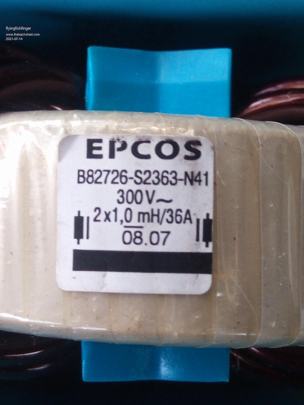 If I put all three (so 6x coils) in parallel, I get 166uH. I'm not sure if the current rating applies to each coil or the whole part but either way that would make 108A or 324A current capability. Sounds to me like this would work as a choke, right? I'll build it up later and try as well. R |
||||
| nickskethisniks Guru Joined: 17/10/2017 Location: BelgiumPosts: 416 |
I don't think it would work,, those chokes you have are common mode chokes. They are used to filter high frequency noise. Not suitable for energy storage. |
||||
| poida Guru Joined: 02/02/2017 Location: AustraliaPosts: 1389 |
I think one or more of those chokes will be useful. Maybe do some saturation tests? The choke's requirements: my design running conditions are 100V in 50V out 20kHz PWM 45 Amp max output current. 100V down to 50V conversion means a 50% PWM width. At 20kHz, this means the pulse width is 50% of 50uS or 25uS Delta V is 100 - 50 Volts and that is what the inductor is exposed to for that 25uS. inductor equation V = L x dI/dT re-arranging for L we get L = V x dT / dI dI = 15 Amps ripple, say V = 50V dT = 25uS L = 50 x 25E-6 / 15 = 83 uH In practice, I found something like 100uH to be good, which means about 15Amp ripple going into the output capacitors. More Henries means less ripple. It's a linear relationship. Ensure the choke does not saturate too much at your required output current. Some saturation, e.g. a 1/2 of inductance during the last 20% of the pulse width is minor. (that is, you will see the current increase 2x faster when measured and shown on the DSO at the end of the pulse) The effective inductance is the straight line of the current through the inductor for the whole width of the pulse, going from zero current to the end of pulse current. A time averaged measure of the inductance over 50uS, for the 20kHz pulse I found it very instructive to test the inductor in circuit, observing the current through the inductor alongside the voltage at the switch node. You will see the DC current and on top of that, the ripple current at various operating conditions. wronger than a phone book full of wrong phone numbers |
||||
| Warpspeed Guru Joined: 09/08/2007 Location: AustraliaPosts: 4406 |
It may also be a good idea to run it for an extended time at very slight load and test for any significant core self heating. There will be a considerable constant square wave 50% duty cycle ac voltage impressed across that choke, and volts per turn are going to create some significant ac flux swing. Core losses will vary greatly with the material. It could run stone cold, or it may get very seriously hot. There is a big difference in running the same identical 100uH choke in an inverter with duty cycle modulated PWM at 48v, and at constant maximum worst case 50% duty cycle in a solar controller at 150v. It will probably be fine, but a half hour run at low load current will definitely tell you. Cheers, ĀTony. |
||||
