
|
|
Forum Index : Electronics : 150V 45A MPPT - roll your own
| Author | Message | ||||
| flyingfishfinger Senior Member Joined: 12/09/2020 Location: United StatesPosts: 102 |
Update to share. I finally installed the MPPT at my site, but didn't have time to wire up all the panels. The net result is that I've only tested it to 800ish W, which works great. Specific observations: - At least up to 800W, the I2C communication is very stable, no errors or reboots due to inductor current. I did make a point of routing the negative inductor wire UNDER the PCB by the heatsink so it wouldn't run right past the I2C traces on the PCB - Referring to my previous post, I changed the code so that the "absorb" mode doesn't use a timer but terminates when the charge current drops to 15W. As far as I understand lead acid charging, ideally one would wait until the absorb current goes more or less to zero, then switch to float but some chargers use a timer, like poida's original code. - The "zero" current behaves weirdly. The current sensors have a DC offset that is included, so sometimes the current is actually correctly zero. But if the controller is reprogrammed (with the same offset and scaling) or restarted, the current is no longer zero. I am not sure why this happens yet. I also found that sometimes the current is negative (about -0.1A when disconnected) so overnight my accumulated total kWh actually REDUCES. Added some code to prohibit negative currents, not sure if it works. - The inductor buzzes once a minute when the PWM is swept. I doubt this is a problem, but it sounds kind of cool. - My Nanocontroller PCB to mount the Arduino directly on the board seems to work fine. I did bypass the overcurrent detection since right now there aren't any external current sensors. It's also missing a fan control output (oops) which needs to be added to the design unfortunately. I got 5 of them assembled, so maybe I'll just try hacking it in instead. - My Arduino Nanos appear to be Chinese knockoffs from Amazon. They don't have the full memory range available! The MPPT code takes up 93%+ of code space, but these Nanos crash if that is uploaded. I had to abbreviate basically all the printable strings down to a few characters to hit 92% code space used, then it worked. Pics: 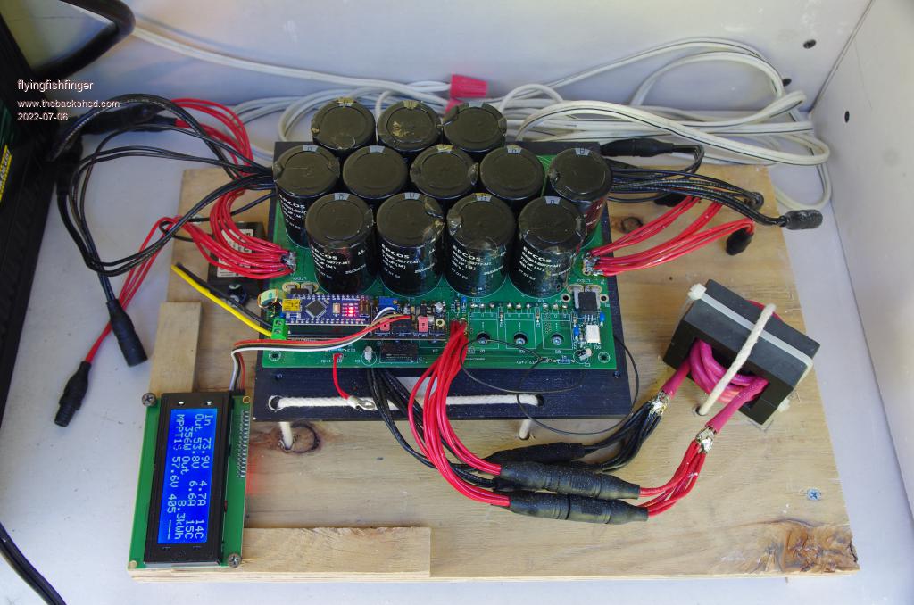 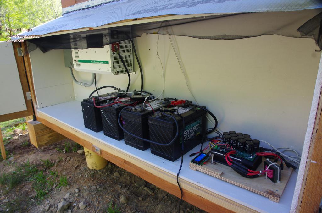 |
||||
Madness Guru Joined: 08/10/2011 Location: AustraliaPosts: 2498 |
You may or may not get to 15W charge. What I have used for many years now is to stay in Absorb until current does not reduce and set that as float trigger. I would separate your batteries from your electronics, they discharge a little acid mist which will take it's toll. Perhaps put a divider in the middle and batteries to the right and ad a vent fan. I have mine come on when the voltage is above 51. There are only 10 types of people in the world: those who understand binary, and those who don't. |
||||
| flyingfishfinger Senior Member Joined: 12/09/2020 Location: United StatesPosts: 102 |
It did reach 15W eventually, so it works if I wait long enough. Will look into your idea though, it also sounds reasonable. I do want to add a load dump output to this. My initial thought was to wait until the thing enters float, then switch to the load but absorb takes too long. Time slicing the output would probably work, but it might thrash the transistors pretty heavily. Although, if done once a minute it might be OK. Incidentally, SolarMike recently posted a little board to do just this (DC SSR), saves me a design cycle! Agreed, the layout isn't ideal yet. I stuffed everything together in a bit of a hurry to make sure everything works, it all needs some tweaking. Perhaps I'll build a "shelf" above the batteries with a fan & duct underneath. The MPPT was meant to hang on the back wall, but my standoffs aren't bolted to the heatsink and the epoxy came loose, so the PCB would be hanging off the MOSFETS - bad idea. Didn't have time to fix it on this trip, so I just laid it down for now. R Edited 2022-07-06 07:58 by flyingfishfinger |
||||
| poida Guru Joined: 02/02/2017 Location: AustraliaPosts: 1389 |
Well done to get it working with the fake Nanos. The buzz every minute is normal, that is when it does a sweep of PWM duty widths looking for max output power. sadly the current sensing is not perfect so the small zero offsets remain an irritation. Good to see you altering the code to suit your needs too. wronger than a phone book full of wrong phone numbers |
||||
| rogerdw Guru Joined: 22/10/2019 Location: AustraliaPosts: 800 |
Congratulations on getting it going and good luck with finishing it all off. It's always interesting to see how others approach a project and add their own particular bent. And I had to keep doublechecking the date on your post Madness ... haven't seen you here for several years. Good to see you back, hope you hang around. Cheers, Roger |
||||
| rogerdw Guru Joined: 22/10/2019 Location: AustraliaPosts: 800 |
Hi Poida, this is a quote from a long time back, May 2021. Just doublechecking my understanding ... D3 is pulled low momentarily to instigate an equalisation charge program ... so I don't want to keep it held low or it wont be able to exit the equalisation segment? And pulling D2 low shuts off output from the MPPT completely ... and then allowing it high again, fires it up again? Thanks. Cheers, Roger |
||||
| poida Guru Joined: 02/02/2017 Location: AustraliaPosts: 1389 |
Roger, D3 is checked once a second and if it's pulled low for one second then EQ mode is enabled. It's a momentary switch. To cancel, pull it low again for a second. wronger than a phone book full of wrong phone numbers |
||||
| rogerdw Guru Joined: 22/10/2019 Location: AustraliaPosts: 800 |
Thanks Peter. Does that apply in the same way to D2 to shut down battery charging ... or does than need to be held low to keep it off? Cheers, Roger |
||||
| flyingfishfinger Senior Member Joined: 12/09/2020 Location: United StatesPosts: 102 |
After building the full setup with my Nanocontroller V1 board, I decided to make some updates. In particular as stated earlier, I forgot connections to drive fans for the heatsink (& inductor). Since most PC fans are 12V, I added two NMOSFETS plus two standard PC fan headers - 3 pin connectors. It's also always good to have extra GPIO pins, so there's a new header that breaks out 4 of the remaining Nano pins - I specifically want to use one or two of these to control the dump load / water heater SSR later. Finally there's a "Power" header that provides extra 5V, 12V and GND pins which could be used to power any external boards. It still looks the same, outline-wise, but it got a bit more stuffed: 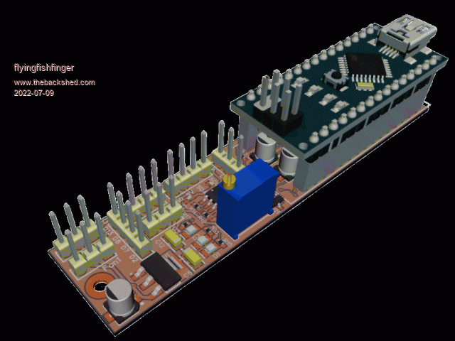 This can be almost fully SMTd by JLCPCB, besides the headers which they don't stock. Happy to share, if anyone wants to try it out! R Edited 2022-07-09 09:27 by flyingfishfinger |
||||
| rogerdw Guru Joined: 22/10/2019 Location: AustraliaPosts: 800 |
Haha, now I see this. I have just spent the last 3 weeks learning pcb design etc and adding the nano's and all the additional bits to the original board. Only last night I finally reached a stage where I'm ready to say enough is enough and just order some and see if it works. I would love a copy of your work please, just to compare with what I've done and in case I've missed anything serious. I'll pm you. Thank you. Cheers, Roger |
||||
Revlac Guru Joined: 31/12/2016 Location: AustraliaPosts: 961 |
Peter, I have the trim pot on the nano brain board to test with, should it be removed before running the latest mpptv5_BV_tempco, or is it ok to leave it there? Cheers Aaron Off The Grid |
||||
renewableMark Guru Joined: 09/12/2017 Location: AustraliaPosts: 1678 |
Nice and compact mate, how have you found RF interference? I used a shielded cable for the mad pwm controller, that works fantastically. If you just use nano jumper cables it turns to sh*t, but run with the shielded it's 100% fine, ran for years without an issue. Roger, if you get some made up i'll buy a couple. Cheers Caveman Mark Off grid eastern Melb |
||||
| poida Guru Joined: 02/02/2017 Location: AustraliaPosts: 1389 |
D2 is checked very frequently and if it's LOW, PWM or output power is reduced to near zero within a few seconds no matter what the battery voltage is and the Absorb voltage setting. If its HIGH (5V) then it's up the the charge settings to determine output power. It is an override of everything that only works as a power control that can reduce output if used. I made this in response to Mark who wants to limit charge current from 2 mppt to about 70A in total. wronger than a phone book full of wrong phone numbers |
||||
| renewableMark Guru Joined: 09/12/2017 Location: AustraliaPosts: 1678 |
Thanks mate, I have been a bit slack with the electronics as I was building a family caravan from scratch inc chassis....all done now, so back to other projects, including this one. I need to re do my whole off grid wall, it's a mess now with all the tacked on additions. I'll fire up the Warp inverter, move the nanoverter and clean up all the wiring etc. Plenty to do in that corner. Cheers Caveman Mark Off grid eastern Melb |
||||
| poida Guru Joined: 02/02/2017 Location: AustraliaPosts: 1389 |
the trimpot was added to provide a voltage to compare with that output from a current sensor that was put in series with the choke. It was a poorly performing attempt at a short circuit protection thing. I think the firmware has a setting that enables or disables this useless thing. In the setup menu, please choose "U - fast OC enable " to be OFF Once you set this to be OFF, it does not matter about the trimpot. The over current input to work needs to have the pin 2 of a 3 pin header labelled "out" to be higher in voltage than the trimpot output and the OC flag = ON to maybe limit output current and not blow up the 2 FETS should you short the output. It sort of worked. But testing also had a session when it did not protect things and I blew both FETs. I think it best we just don't use this and set it to "OFF" and move on in life...look for a coldie in the fridge..see if the cricket is on TV.. on in my case, look up, see no rain and get on the mountain bike to get some good fun going. wronger than a phone book full of wrong phone numbers |
||||
| rogerdw Guru Joined: 22/10/2019 Location: AustraliaPosts: 800 |
Thanks again Peter, that clears it up for me. I can see it being useful with several charging sources on a battery. And I'll keep you posted Mark. You're certainly welcome to some but with my lack of pcb design experience, I wonder if I should just get a minimum to start with and see if they do work properly ... and then it won't be an embarrassment if they're not up to scratch. Cheers, Roger |
||||
| renewableMark Guru Joined: 09/12/2017 Location: AustraliaPosts: 1678 |
I know you have put a bit of work in, but maybe it's easier to use FFfingers board? FFfinger, what did jcpcb quote you to make the populated boards? Cheers Caveman Mark Off grid eastern Melb |
||||
| flyingfishfinger Senior Member Joined: 12/09/2020 Location: United StatesPosts: 102 |
$50 total for 5. Dirt cheap if you use parts from their library! I haven't tested past 800W yet since I haven't wired up all the panels, but so far it's been rock solid! Not a trace of hanging, interference or rebooting. Attached is the current schematic for reference, comments or questions. NanoControllerV2.pdf I haven't finished assigning part numbers & getting a quote for V2 yet, give me a day or so then I'll share the whole thing. Cheers, R Edited 2022-07-10 16:00 by flyingfishfinger |
||||
| rogerdw Guru Joined: 22/10/2019 Location: AustraliaPosts: 800 |
If I hadn't done all this work I most certainly would have been keen to try that ... and certainly much easier ... but because I have put so much time and effort into it, I do need to know if it works or not. All part of my education. Thank you very much for the circuit, very handy to compare. You have obviously modded the code to make your changes by the looks. And I certainly like that you've been able to make it work with just one Nano and not two. Your Nano pinout numbers threw me for a while though.  Cheers, Roger |
||||
| flyingfishfinger Senior Member Joined: 12/09/2020 Location: United StatesPosts: 102 |
I'm curious about what changes you've made / what your version looks like. Care to post it? Would be happy to review as well. Here's my layout (Diptrace source, it's not quite ready yet), I'll post Gerbers when I'm satisfied. FWIW, I posted V1 (or at least an image and the fact that I made it) about 6 months ago - would have been happy to save you the weeks of effort if anyone had asked... R NanoControllerV2.zip |
||||
