
|
|
Forum Index : Electronics : 150V 45A MPPT - roll your own
| Author | Message | ||||
| flyingfishfinger Senior Member Joined: 12/09/2020 Location: United StatesPosts: 118 |
Other question: You code has menu option "B - max inductor temperature" commented out, even though it seems to be a valid selection and has a function for some actions associated with it. Is it intended to be present? And, one more thing, rather more important I think: If I have working previously running controller (i.e hooked up to cells and batteries) then flash the new software, what happens to the default / EEPROM settings? They should be preserved as they were before, yes? If not, is this dangerous from a switching / powered-up point of view to have them be uninitialized until "Z" is pressed? Edited 2023-11-22 11:48 by flyingfishfinger |
||||
| poida Guru Joined: 02/02/2017 Location: AustraliaPosts: 1432 |
FF: both firmwares have a battery temperature compensation function and I use the inductor temperature sensor as input. We are supposed to put the inductor temp sensor on a battery terminal. I wanted BV absorb tempco much more than I wanted the inductor temperature. So no further need for that option in the menu. The EEPROM data will remain valid and usable when you flash new code. I made sure to keep the storage locations consistent between versions. have a look at _nvdata structure, I add new things at the end of it. I would ask that after flashing, you will need to review the settings and put some sensible defaults into these: Battery temp offset (use zero) BV tempco (zero again) Absorb BV std. temp (25) Please do not choose Z from the menu. NO need to do this. I have flashed controllers 100x while running and connected to inputs and loads. changing things from the menu while it's running is also safe (assuming we do not do silly things) Edited 2023-11-22 14:24 by poida wronger than a phone book full of wrong phone numbers |
||||
| flyingfishfinger Senior Member Joined: 12/09/2020 Location: United StatesPosts: 118 |
I updated all the defaults from 'Z' with my values, in case I have to reinit on a new Arduino or anything. But thanks for the clarification on the EEPROM persistence! For the temperature compensation. Do you actually use it to adjust the charging theresholds? If yes, what do you set for the first two? R |
||||
| poida Guru Joined: 02/02/2017 Location: AustraliaPosts: 1432 |
I use the BV absorb tempco for 18 months or more. My battery needs the absorb voltage to be modified by about -0.12V per degree over a range of 15 degC to 40 degC this is from the manual for my battery (blue is absorb/equalisation) 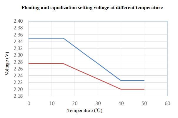 which is this data 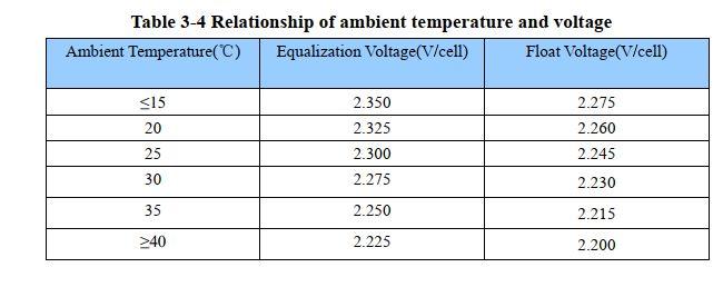 Battery temp offset is used to trim the 10K NTC thermistor to within a degree of what is shown from a K type thermocouple This is only -1 in my case. BV tempco is set at -0.12 for my battery Absorb BV std. temp is needed as well, since I am using a simple linear function. A linear function needs an offset and a slope. The battery manufacturer chose 25 degC as my offset. This setup works flawlessly and continuously modifies the max charge voltage depending on battery temperature. The code that works out the temperature modified charge voltage is float bv_tempco_adjust(float base_temp) { // modify target battry voltage by the tempco and the inductor NTC temp // limit the correction to temperatures > 10 and < 35 degC // temperatures outside this range will be clamped to the limits float temp_diff; temp_diff = inductor_temp - nvd.absorb_temp; if (temp_diff < -15.0) temp_diff = -15.0; if (temp_diff > 10.0) temp_diff = 10.0; return base_temp + nvd.bv_tempco * temp_diff; } I like this a lot and include it in the current firmware. To nullify it, just set the default values as I showed before: Zero BV tempco Zero temp offset 25 for standard temp wronger than a phone book full of wrong phone numbers |
||||
soudirector Newbie Joined: 14/05/2023 Location: NigeriaPosts: 26 |
|
||||
| poida Guru Joined: 02/02/2017 Location: AustraliaPosts: 1432 |
maybe it's a communication problem between serial console and nano. I recall sometimes sending 'C' or a few other letters to the nano would result in nothing at all happening. I tried different line ending choices as well as tried sending the text (a single letter from the keyboard) simply by pressing 'enter' but also clicking on the 'Send' button. There are 4 ways to complete the line of text that is then sent to the nano (or other controller) when using the Arduino serial console. Newline Carriage Return NL & CR No line ending where newline is the character 10 (in decimal) and carriage return is 13 The serial console will send data just by you pressing the 'enter' key after putting the mouse cursor on the top text area and typing something. It will append the chosen line ending to the text before sending it. I think the line ending that will work is Newline so try that and see how it goes. wronger than a phone book full of wrong phone numbers |
||||
| Ziki_the Newbie Joined: 13/04/2023 Location: YugoslaviaPosts: 39 |
So, with updaded code i have no transition from absorb to float.. Time has elapsed. Starting(when is powered up) is from mppt, not night mode like is use to be. I use baterry for input, one charging other discharging. Maybe i used some old code before.. Is someone could check. Thanks  Re_uploded and working... Edited 2023-12-15 04:49 by Ziki_the Pozdrav iz Srbije |
||||
| nickskethisniks Guru Joined: 17/10/2017 Location: BelgiumPosts: 462 |
Just some things I want to share about the tracking algoritm. Since I'm replacing my older with newer higher voltage panels I've noticed some troubles finding the tracking Point. When output current is around 10A I see a robust mpp. But with lower current it's switching between 60 and 80V input voltage... My mppt controllers have a relative small inductance +-50uH. Wich was enough to convert +- 60V to +-52V. And I've never seen tracking issues. I now have around 74V so this makes more than double the voltage difference and this requires more inductance to let the current ramp up more slowly. I've noticed a second issue in my system, and that's the ripple current/voltage (100Hz) produced by my inverter. I have connected a current clamp to my scope and the buck inductor and there I could clearly see a 100Hz current waveform combined with the 20/40khz of the mppt controller. So when the inverter was drawing decent current it probably has a bigger influence on the the tracking algoritm then a to small inductance of the buck inductor. I should probe the output current sensor but I think I would see a simular result without the 20/40khz component. When the solar current is high compared to the ripple the inverter is pulling this would have no influence. But apperently my inverter is using the capacitors of my mppt controller  I will post some scope pictures if I have the opportunity. |
||||
| mab1 Senior Member Joined: 10/02/2015 Location: United KingdomPosts: 242 |
I'm using mine with an input of about 130 - 140v mpp, into a 24v battery. Iirc my inductor is only about 88uh, but even at 20kHz only the inductor gets warm. Due to the high vin/vout ratio i did have to modify the mppt algorithm (by default it scans pwm from around 1 up to 833 in steps of 20:- as all the action takes place with pwm below 190 on this setup i needed a smaller step size up to 190). I still have mppt tracking issues below 5a and especially below 1a - i hadn't ever considered that the 100hz ripple from the inverter could be the issue! Not sure how you would filter that out, but perhaps i/we should try connecting the mppt controller directly to the battery terminals (mine goes to the d.c. bus)? |
||||
| nickskethisniks Guru Joined: 17/10/2017 Location: BelgiumPosts: 462 |
If I'm not mistaken there is a RC filter on Peter his controller boards, 10uF and 10K I think. So there is already filtering, then the signal is even filtered more in the software, so I don't know how much this does. I'm glad (or actually not  ) you see the same thing at lower currents. ) you see the same thing at lower currents.It's just a theory I have, so I'm looking forward to the comments.  A way to rule this out is to test on a system without inverter, that is the next plan. Here there is a waveform of the input current, (readings are actually 1/10 so around 3-5A at that time, I don't know) The current probe I'm using is a micsig CP2100B and it's picking up switching noise quite easily, not all noise is actually real. I think this is a quite usual waveform, although you can already see some 100Hz influence. 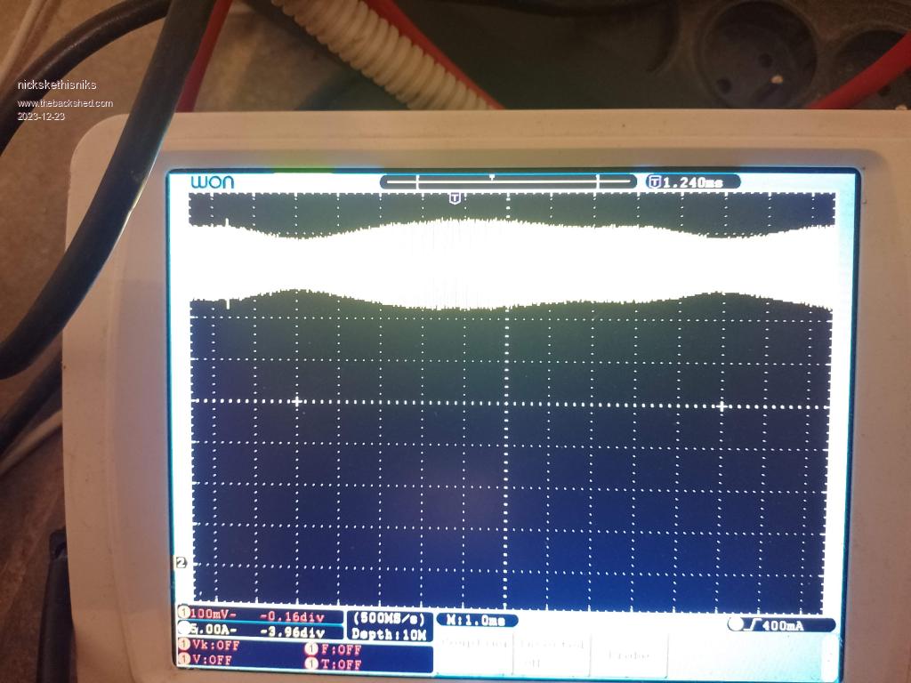 Next image is on the outputcurrent (again actual current is 1/10 of the current measured) What we expect is a rather clean DC waveform but there is a substantial AC ripple current, coming from reactive components and/or current ripple because of long wires between my battery and inverter. Power was only 2-300W (at 48V) at the time. 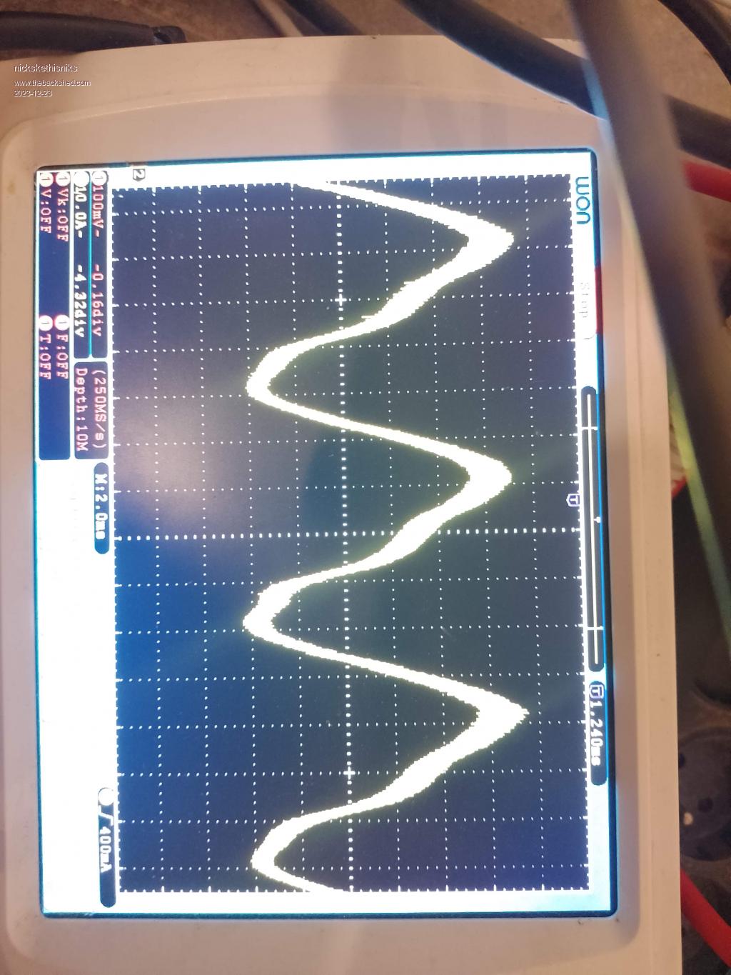 Next a waveform of the current thru the buck inductor (I had polarity wrong) 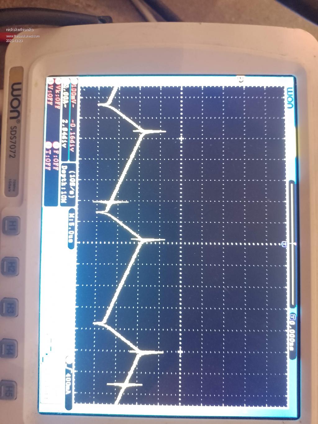 Then with longer timebase ( again polarity wrong) you clearly see the 100hz again 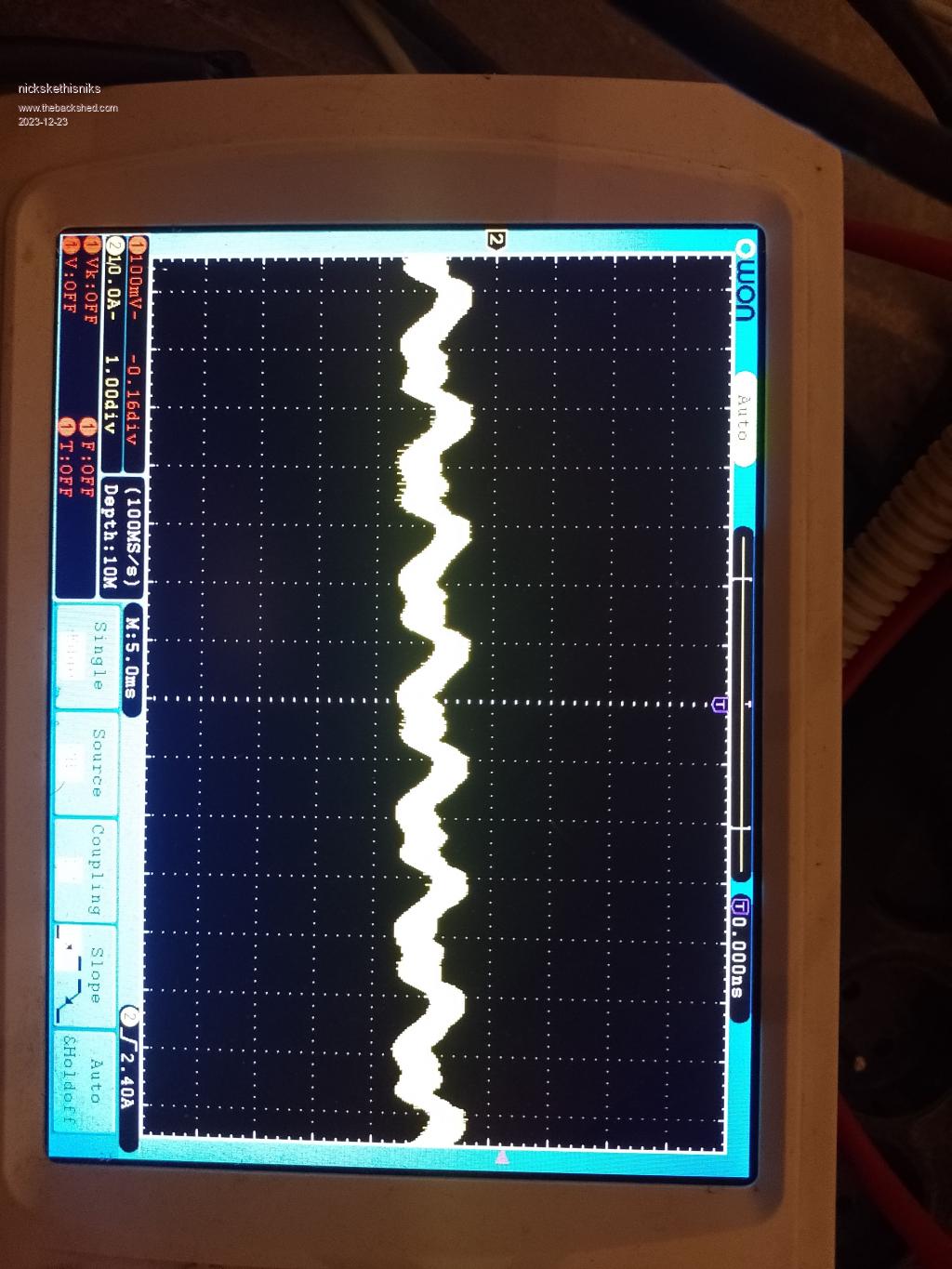 Sorry for the turned pictures..... Edited 2023-12-23 07:32 by nickskethisniks |
||||
renewableMark Guru Joined: 09/12/2017 Location: AustraliaPosts: 1678 |
Mab, I had a number of issues early on, one of them was traced after many blow ups to the large charge (up to 160A) going into the bus bar close to the inverter. When it got connected directly to the battery it stopped the blow ups. I can't remember the fellows name, he lives around the vic border, but he had the exact same experience. I seem to remember someone, it might have been from NZ saying to use a nickel? washer between the connections. I think it was between the charge controller and battery. I never did that as moving the current input to the battery solved my problem. Cheers mate have a good xmas. Cheers Caveman Mark Off grid eastern Melb |
||||
| Solar Mike Guru Joined: 08/02/2015 Location: New ZealandPosts: 1162 |
Best advice is to connect your charger with short heavy gauge cable + fuse direct to the battery terminals; being the lowest impedance point and thus least influenced by external reactive loads, such as your inverter. As your PV input voltage increases relative to the battery, then to reduce charge ripple current, the buck inductor should be increased in value. Cheers Mike Edited 2023-12-23 09:19 by Solar Mike |
||||
| mab1 Senior Member Joined: 10/02/2015 Location: United KingdomPosts: 242 |
Thinking about it, the ripple your seeing is a direct result of voltage ripple on the battery voltage: as the pwm ratio is constant between tracking adjustments or scans, then the current through the controller inductor will go up or down as the battery voltage goes down or up; so the analogue and digital filtering on the inputs to the nano will have no bearing. In my case i had come to the conclusion that my low current tracking issues were due to my high 5:1 vin:vout ratio, and the fact that i packed the board with 560uF caps from a GTI. When the output current is <1a the input current is <0.2a and you can see the input capacitance voltage rising slowly post-mppt scan. I partially solved it by slowing the scan right down at low power levels, but still found it was often missing the MPP - your 100hz ripple might well be the issue as it could easily swamp the small current variations with pwm. I was planning at some point to replace the input caps on mine with smaller ones, but have to bear in mind that when running at 45a output the input caps still have to supply 40a when the mosfets are on. Still not sure how we can stop the 100hz ripple current though, or stop it showing up in the mpp scan currents |
||||
| phil99 Guru Joined: 11/02/2018 Location: AustraliaPosts: 2608 |
A possible alternative to trying to combat 100Hz ripple is, at low power, to switch from measured MMPT to estimated MMPT. For most solar panels the ratio of voltage to current at max. power remains fairly constant over a wide range of solar input. Eg. If a 1kW array that outputs 100V @ 10A at max. power when in full sun, may have in cloud a max. power of 100W when delivering about 33V @ about 3.3A. In this example just maintaining that 10 to 1 ratio will be close to max power for any solar input. Measure the array voltage and current to continually adjust the PWM to maintain that ratio, ignoring what is happening on the output. As this mode is only used at low power any inaccuracy will cause little loss of energy storage. As usual this is overridden when the battery is full. |
||||
| mab1 Senior Member Joined: 10/02/2015 Location: United KingdomPosts: 242 |
I must have forgotten to refresh my browser when i did my previous reply - i hadn't seen renewablemark or solar mikes replies when i posted - or after, somehow. Yes i think I'll try connecting directly the the li battery terminals  . I was wondering if nick has his connected direct or not? . I was wondering if nick has his connected direct or not?If that does remove the random element to the mppt scan, then i may also try a version of phils suggestion at low power levels (i.e. not scanning every 1 minute), as my slow charging cap bank makes the scan slow (waiting for the caps to get well above mpp voltage). Although modding the code for longer scan intervals might be a bit more involved than modding the scan itself... Cheers, and merry Xmas! Edited 2023-12-23 20:40 by mab1 |
||||
Bryan1 Guru Joined: 22/02/2006 Location: AustraliaPosts: 1448 |
G'Day Guy's, When I did the order from digikey I just used the BOM recommended in the zip file for the MTTP, now the VS-60EPU02-N3 200V 60A diode is a 2 leg diode so on the board it's connected to gate and source which are tied, so does this mean I need to bend one leg to go on the middle drain hole? As this package is a single diode and all I did was copy and paste the parts numbers off the BOM to digikey I just want to make sure as I don't want to blow another board up.... Cheers Bryan Edited 2023-12-24 13:20 by Bryan1 |
||||
| Ziki_the Newbie Joined: 13/04/2023 Location: YugoslaviaPosts: 39 |
Hi Bryan1, Yes you have to bend one leg, and that is left leg(left and center are connected?). So right leg is like S mark on board. Pozdrav iz Srbije |
||||
| Bryan1 Guru Joined: 22/02/2006 Location: AustraliaPosts: 1448 |
Ok so I did do the right leg to drain and on checking the anode is going to the choke input and the cathode to ground so have got this backwards ??? Now I put the left pin to the gate aswell. Edited 2023-12-26 16:54 by Bryan1 |
||||
| Solar Mike Guru Joined: 08/02/2015 Location: New ZealandPosts: 1162 |
Refer to the manufactures spec sheet, it quite clearly shows where the package pins connect to. Data Sheet Cheers Mike |
||||
| Bryan1 Guru Joined: 22/02/2006 Location: AustraliaPosts: 1448 |
Thanks for that Mike in the morning I'll de-solder the diodes and move them across on hole which will correct it |
||||
| The Back Shed's forum code is written, and hosted, in Australia. | © JAQ Software 2025 |
