
|
|
Forum Index : Electronics : 150V 45A MPPT - roll your own
| Author | Message | ||||
| Solar Mike Guru Joined: 08/02/2015 Location: New ZealandPosts: 1162 |
I have been playing with a new controller design, it won't have an inverter fitted to the battery, but I connected a HF 3.5KW 24dc-230vac inverter and checked out the output of the charge current sensor. With a load of 500 watts or so there is a 100hz ripple on the dc current sensor output, approx 100mV; just over an amp charge. At low charge currents this 100mV ripple causes in my case abnormal MPPT current tracking data, with higher charge currents 10's of amps, has little affect. I got around this issue by over sampling the charge current by 512 times and dividing the result by 512, rejecting any decimals, this averaged out the 100 HZ DC ripple and now works ok. On other controllers I usually have a 10Hz 18db active filter after the sensor, so the problem hasn't been evident, this particular design doesn't have it. Cheers Mike |
||||
| nickskethisniks Guru Joined: 17/10/2017 Location: BelgiumPosts: 462 |
Thanks Mike. When connecting the charge controller directly on the battery (but still 5m cable) the ripple is reduced by half. |
||||
| -dex- Senior Member Joined: 11/01/2024 Location: PolandPosts: 101 |
Hi, I would like to build this MPPT controller for myself. Due to the number of PV panels in my system, more than one MPPT system is needed. The main unknown for me is can I connect 2 or 3 chargers in parallel? We are talking about a situation in which each charger has its own individual string of PV panels and that they all charge the same battery. |
||||
| nickskethisniks Guru Joined: 17/10/2017 Location: BelgiumPosts: 462 |
Yes, I do it like this, I know that more people are doing this over here. |
||||
| rogerdw Guru Joined: 22/10/2019 Location: AustraliaPosts: 904 |
I have built four of these and will parallel them all up once I fit the remaining panels. I have 4 banks of 3kW ... 3s4p. Half are older 250watt panels and the rest 275watt. If I ever decide I need more, I possibly would use an older grid tie inverter and connect to my own mini grid. Cheers, Roger |
||||
| -dex- Senior Member Joined: 11/01/2024 Location: PolandPosts: 101 |
OK thank you for the information. Where can I find the latest version (diagrams & gerbers) and software for it? |
||||
| rogerdw Guru Joined: 22/10/2019 Location: AustraliaPosts: 904 |
I have a question about the settings ... particularly the "tolerance" settings. I have only noticed my setup go into float a couple of times ... and with the good solar days we've had lately, I would have expected it to get to float easily enough. I'm using an ex forklift FLA battery, 48V 980Ah which is in reasonable condition and have set Absorb to 59.6 and for 3 hrs. Tolerance is the default 3.0 volts. Is the tolerance to allow for eg. cloud cover reducing output for a short while ... without restarting the Absorb timer all over again ... or am I completely wrong? Thanks. Cheers, Roger |
||||
| poida Guru Joined: 02/02/2017 Location: AustraliaPosts: 1432 |
it's been a while since I've looked at this part of the code. separate tolerance settings exist for absorb and float. the idea is that at some time, BV will get to the absorb setting. this means it will no longer care about MPPT and just maintain the battery at absorb voltage. this is because there is more than enough solar to keep the battery at absorb voltage. And when it first gets to absorb voltage it starts a timer. The timer sets how long to have battery at absorb voltage. the timer will count down while BV > (absorb voltage - absorb_tolerance) this is to allow for inverter transient loads and minor clouds and such. No point in bailing out of absorb mode just because a fridge switched on, dragging BV down 3 volts. There is an absorb time setting. This has to be achieved before float mode will be enabled. so, lets say float mode is finally enabled. Again, BV needs to stay above (float - float_tolerance) to remain in float mode. if BV is less than (float voltage - float_tolerance) then it goes back to MPPT mode and it's likely to quickly then go to absorb mode. Edited 2024-02-15 18:01 by poida wronger than a phone book full of wrong phone numbers |
||||
| rogerdw Guru Joined: 22/10/2019 Location: AustraliaPosts: 904 |
Yep okay thanks. It was the dropping back to MPPT which was worrying me, which you've explained below. Yes, understood. I think this is what I was missing. I had no idea how much varying loads on the inverter ... and outside weather conditions would effect the levels and so quickly. I understand the theory okay (I think) but this is my first real solar system, so still more to learn. Yep, understood. Okay, so this is what I've seen a few times. So if this happens, from Float back to MPPT ... then on to Absorb again ... does the Absorb Timer start from the beginning again? I think I might lower my Absorb setting a smidgeon, and perhaps widen the tolerance just a bit as well. At least I understand what I'm looking at better now. Thanks very much Peter. 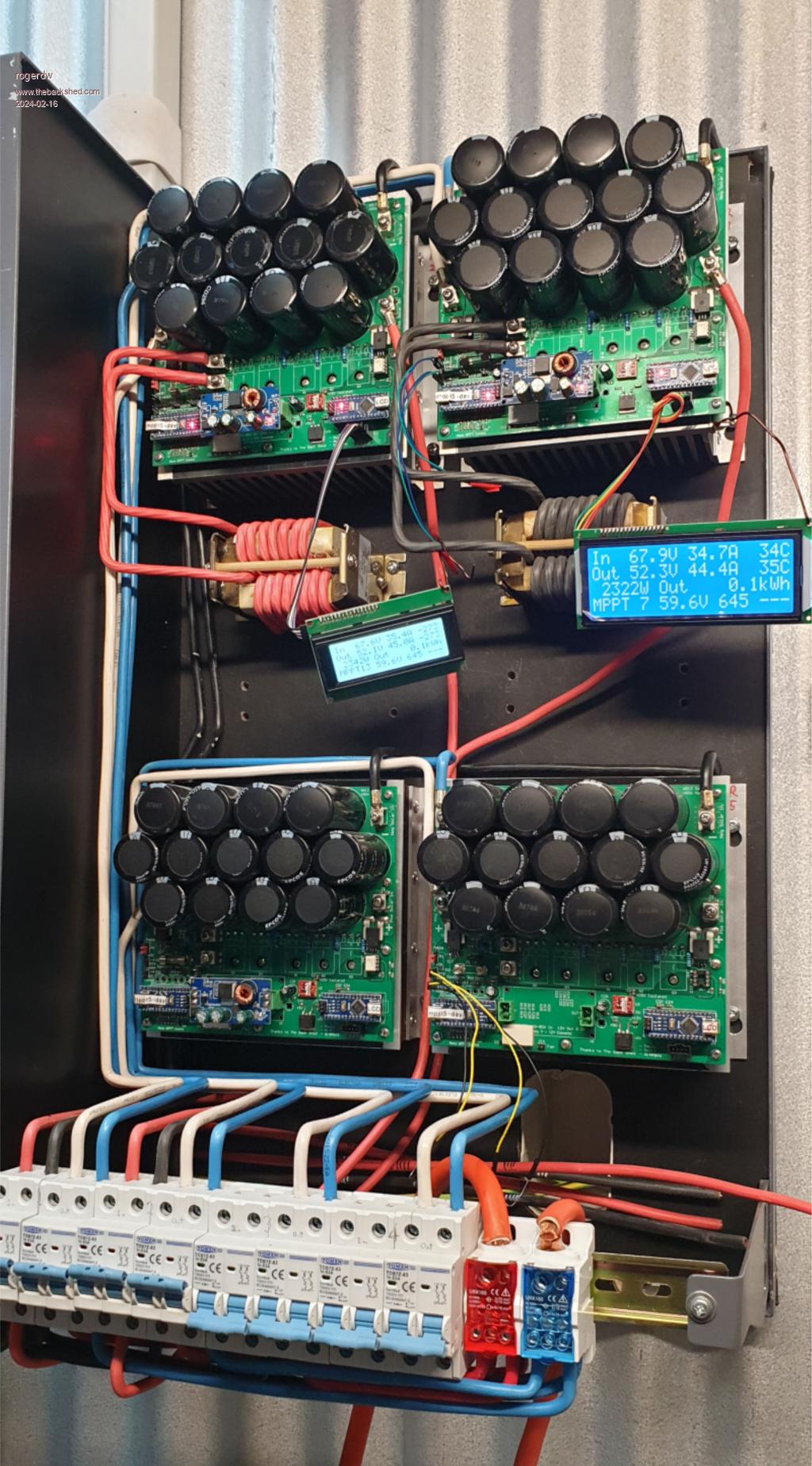 Cheers, Roger |
||||
| poida Guru Joined: 02/02/2017 Location: AustraliaPosts: 1432 |
Yes, the absorb timer will be reset when it drops out of absorb mode. I was educated by looking at my battery as it's voltage rises as it approaches the absorb voltage. The voltage rises very quickly. If I wanted to use the float charge function, I would use a large absorb tolerance. This is to permit large voltage variations and still remain in absorb mode, counting down the programmed time. I suppose a better way would be to time average battery voltage and then do the BV < (absorb - absorb_tolerance) decision. That would be nice, actually, now I think about it. If we sample BV each second over 5 minutes (300 times) and average this, it will permit short BV drops due to motor startup and other things to occur without upsetting the absorb period. your work shown above looks great. the top right mppt is running at 67.9 V x 34.7 A or 2356 W input from the panels it's about 98% conversion efficiency. not too bad at all. here is when my battery approaches absorb voltage. See how fast it rises with nearly constant charge power (or current) and how fast the charge power drops while maintaining absorb voltage! Dark Blue is charge power Light Blue is battery voltage it seems to me that my battery (everyone else's battery will be different) is very sensitive to charge current when near absorb voltage and nearly anything will make BV drop. 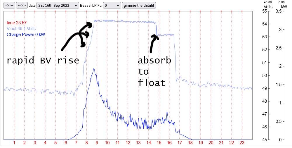 Edited 2024-02-16 17:54 by poida wronger than a phone book full of wrong phone numbers |
||||
| rogerdw Guru Joined: 22/10/2019 Location: AustraliaPosts: 904 |
Yes, I can see that now. Explains a lot. That graph is excellent. I need to do the same. I have a feeling at least one of my meters can log data, I'll have to have a look. And yes, I will widen the tolerance to perhaps 5 volts, from the 3 volts at present. What's led me to this is the fact that the battery (forklift type) spends a lot of time bubbling along ... and has gone through a bit of water already. I'm sure if I can give it a solid absorb time ... then get it on to float, it will have an easier life. That's a great idea and I even understand the concept. Of course implimenting that is not something I'm capable of but it could be very useful. Thank you. I was just so pleased and relieved that they all worked okay ... so it's even better to see that sort of efficiency. Thanks for such an excellent design and all the work you've done over the years fine tuning it ... and then giving the design away. Awesome work man. Cheers, Roger |
||||
| rogerdw Guru Joined: 22/10/2019 Location: AustraliaPosts: 904 |
I had an interesting experience a couple mornings ago when I went to check the system ... about 8.30am and I was still a bit bleary eyed. One mppt was showing 777W OUT but the other one was showing "BLOW OUT" ... and I'm trying to work out what sort of sick code Poda had programmed in to make it show that  Actually took me a few seconds to realise it was 810W OUT and not BLOW OUT. Actually took me a few seconds to realise it was 810W OUT and not BLOW OUT.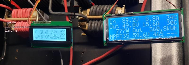 Later the same day I walked past and saw both were pumping out 55A each and 3000W plus. Of course by the time I got my phone out for a shot it had changed. Went up and down a lot for a while ... cloud edge effect?? Not bad for 3.3kW of s/h panels on each. Very happy. Spent the day installing another dozen 250W panels, so will hook up the third mppt shortly. 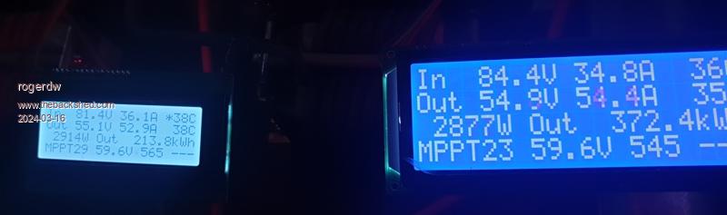 Cheers, Roger |
||||
| poida Guru Joined: 02/02/2017 Location: AustraliaPosts: 1432 |
this is a great result, Roger. The mppts are running at top power level too. Anything getting too warm at 55A? wronger than a phone book full of wrong phone numbers |
||||
| rogerdw Guru Joined: 22/10/2019 Location: AustraliaPosts: 904 |
Yes, I'm rapt that it works so well ... thanks for all your blood, sweat and tears to get it to this stage. The only things that get warm are the chokes ... and the hottest I've seen them are around 50 degrees on those 41 degree days we had recently. Otherwise they float from about 30 - 45 depending on conditions. The heatsinks really don't get much warmer than ambient. I have a barrel fan across the bottom blowing air up past heatsinks and chokes and it comes on at 40 and off at 35. Copes quite well so far. Cheers, Roger |
||||
| -dex- Senior Member Joined: 11/01/2024 Location: PolandPosts: 101 |
What model of MOSFETs and diodes you are using? |
||||
| rogerdw Guru Joined: 22/10/2019 Location: AustraliaPosts: 904 |
Hi Dex, I am using FDH055N15A 150V 156A TO-247-3 Mosfets Element14 PtNo 2825158 STPS61150CW 150V 60A TO-247 Schottky Diodes Element14 PtNo 2806773 Both horribly expensive ... but I figured if I used the best spec I could, hopefully they'll be more reliable and forgiving. And so far I haven't had any fail. I fitted another dozen 250 watt panels on the weekend and hooked up the third mppt. Only thing that's a little disappointing is that the output is quite a lot lower than the other two that each have a dozen 275 Watt panels. While the first two might be pumping out 2,800 watts each, the third one might only be supplying 1,800 watts. Now I'm weighing up if I fit the other 12 x 250 watt panels I have here ... or sell them and buy some more 275 or 300 watt panels instead. Cheers, Roger |
||||
| -dex- Senior Member Joined: 11/01/2024 Location: PolandPosts: 101 |
Thanks. FDH055N15A's price is indeed high, but substitutes have similar prices. As for the diode, I have a nice Samurai double shotky diode (2x30A) in my local store, its cost is the equivalent of ~$2AUD, i think could do the job  shins04528_1-2282124.pdf |
||||
| Solar Mike Guru Joined: 08/02/2015 Location: New ZealandPosts: 1162 |
An alternative replacement is the IRFP4568 made by Tokmas available from LCSC see Link US$1-70 x 10 off Cheers Mike |
||||
| rogerdw Guru Joined: 22/10/2019 Location: AustraliaPosts: 904 |
Wow, certainly cheaper, thanks. I've added some to my cart for future spares. Have you used many under high load Mike? Cheers, Roger |
||||
| poida Guru Joined: 02/02/2017 Location: AustraliaPosts: 1432 |
A lot depends on the load each mppt sees. Let's say you have 2 mppt that are pumping 6kW into the battery. Their Battery voltage calibration are quite close to exactly what the battery is. And you add one more mppt, but this time, it's calibration sees the battery as maybe 0.2V higher than the other 2 mppts. Once the battery gets to ABSORB, the first 2 mppt will be putting in a lot and the 3rd one not a lot at all, if any, since IT sees the battery at ABSORB or even 0.2V over ABSORB voltage. In my system I have two mppts, one taking power from a North facing array (3kW) and one taking power from an East facing array of panels, again 3kW. Most days, when I have clear skies, I see ABSORB around 10am or a bit later. One mppt is doing ALL the work while the other is doing nothing much, maybe 100W or less. This is due to the low power mppt thinking that the battery is exceeding ABSORB voltage and so it throttles back to near zero. As it should. In your case I think you now have 4 mppts, with 4 arrays. (or maybe 3, I am not sure).. anyway, if you are getting to ABSORB voltage then expect one or more mppt to throttle back before the last one does. But when they are all in MPPT mode, then it's different. If the battery voltage is well below ABSORB, then they all should be trying to output full power from what is available from the panels. Of course, one array of panels might well be oriented in a different direction than the other arrays and so it should not be able to produce as much. For best results from the mppts, we need to keep the voltage difference of the battery and the solar array to less than a factor of 2. Maybe even 1.5x. The DC-DC conversion is most efficient when this is the case. It MUST be well above the battery ABSORB voltage though. Edited 2024-03-19 20:23 by poida wronger than a phone book full of wrong phone numbers |
||||
| The Back Shed's forum code is written, and hosted, in Australia. | © JAQ Software 2025 |
