
|
|
Forum Index : Electronics : AndyMc's OZ/MAD/NANO Inverter Build
| Author | Message | ||||
| andymc70 Regular Member Joined: 30/06/2019 Location: AustraliaPosts: 42 |
I used 2mm diameter cable from the old Inverters, i used 22 of them so it should be 70mm2, i can easily wind another 4 strands to take up to 26. They will be on the outside. I think i will have enough room but i wont know until i wind it on. I not sure if i get the chance to do another, trying to find the cheap toroids is getting more difficult. Andy |
||||
| Godoh Guru Joined: 26/09/2020 Location: AustraliaPosts: 379 |
Hi Andy, the best way to get the varnish of enamelled winding wire is to heat it up with a small oxy torch. I used to wind electric motors and that is how I treated the ends of the wires that I wanted to join, then I silver soldered them. If you use a number 8 tip and just heat the ends of the cable up until it is red hot the enamel will just blow off. Other than that you have to scrape it off each wire. Can be done but much slower. Pete |
||||
| andymc70 Regular Member Joined: 30/06/2019 Location: AustraliaPosts: 42 |
I want to start on the chokes, So i started to pull the 2 large chokes aparts from the old inverters. Do they both have an air gap. What do you use for the gap. Also is this part the correct one for the right one. E70 Core What size wire did you use for the one on the right. Thanks Andy |
||||
| Warpspeed Guru Joined: 09/08/2007 Location: AustraliaPosts: 4406 |
Andy, The choke on the left used the original Aerosharp air gaps, which was about 1mm. Its really difficult to measure exactly, because the two steel U halves are epoxied together. Just use them as they are. Cut away all the original wire, then just add the twelve turns of new wire. Twelve turns of 20mm Sq fitted the slot perfectly, and produced 178uH, and from memory it started to go into saturation at around 135 amps. The choke on the right is something Mark already had, so he just connected both in series. It will work perfectly well with just the steel cored choke on the left. So try it with that first, it will have more than sufficient inductance. Cheers, �Tony. |
||||
renewableMark Guru Joined: 09/12/2017 Location: AustraliaPosts: 1678 |
Yeah, you don't need the ferrite one that's on the right. It has 70mm welding wire with the outside orange stripped off BTW. Your link for the ferrite is the correct one, but you don't need it. Those aerosharp cores give off nasty splinters that flake off, so wear really good leather gloves. As Warp said, the chokes already have a spacer there, just use that as it's what was used when Warp did the saturation tests on it. We know using two as is with 12 turns works well, so just copy that. When finished paint it so loose flakes don't come off (they'll conduct) and murhys law, they will end up where you don't want them. The one in the pic has two layers of 25mm2 cable, it's not 20mm2, so be clear on that when you order. I got mine from jaydee in bayswater, they have good prices here The insulation on this is far more durable than others, so don't get the soft insulation type from jaycar etc. get this one Make up a simple bracket from sheetmetal and bolt it down hard so it doesn't buzz. here To bear the enamel wire I just fan it out and scrape off with a knife. Yes it takes a while, but building an inverter will teach you the patience and endurance of a shao lin monk. It may also drive you mental. Edited 2020-10-02 08:13 by renewableMark Cheers Caveman Mark Off grid eastern Melb |
||||
| Warpspeed Guru Joined: 09/08/2007 Location: AustraliaPosts: 4406 |
Mark is quite right, its 26.45mm Sq just had a look at the drum it actually came from. Cheers, �Tony. |
||||
| renewableMark Guru Joined: 09/12/2017 Location: AustraliaPosts: 1678 |
Yes, that's right, I wound the first one with wire you gave me Tony, I got the subsequent cable from Jaydee. Exactly the same tycab stuff. Bloody hell, stretching my memory now, that was a long time ago. That machine is still going strong, just ran out and had a look, it's done 6465Kw hours. I'd say it's tuned pretty well! Thanks again for tweaking and testing all the add on's, it's certainly a good formula to copy. Edited 2020-10-02 08:44 by renewableMark Cheers Caveman Mark Off grid eastern Melb |
||||
| Warpspeed Guru Joined: 09/08/2007 Location: AustraliaPosts: 4406 |
All part of the service ! That choke is a real wonder. It worked out perfect for us the very first attempt. A really good balance of inductance and saturation, and with the air gaps it already had. Plus the wire was a perfect fit through the slot with the ideal number of turns. Cheers, �Tony. |
||||
| andymc70 Regular Member Joined: 30/06/2019 Location: AustraliaPosts: 42 |
Thanks for that TONY and MARK. So i have found the following internal pictures just wondering a few components. Also i have add an image that i can not read correctly when enlarged to see the overall system. I am trying to get a better understanding of how its all put together. 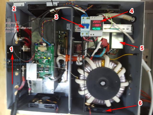 1. I do know what it is? 2. I think is a current shunt. 3. I think this is circuit breaker, what size do people recommend. Also do you just run cable straight to the electrical panel.[I mean you get an electrician to do all this]. 4. I do know what it is? 5. I do know what it is? 6. Fan what size do you recommend, is bigger better. I was looking at 140mm 12v. Also what/how have you setup the front panels of the inverters. If you have picture that would be great. Here is the schematic that i can not read when i enlarge it. 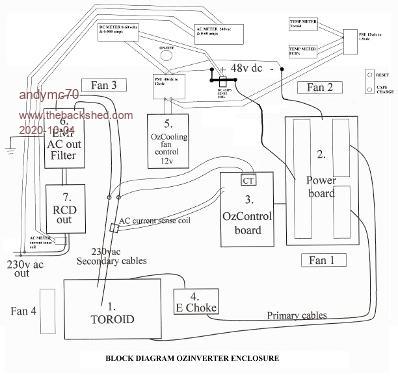 Also i am wondering how you remove the old toriod holder shown here on the left hand side. 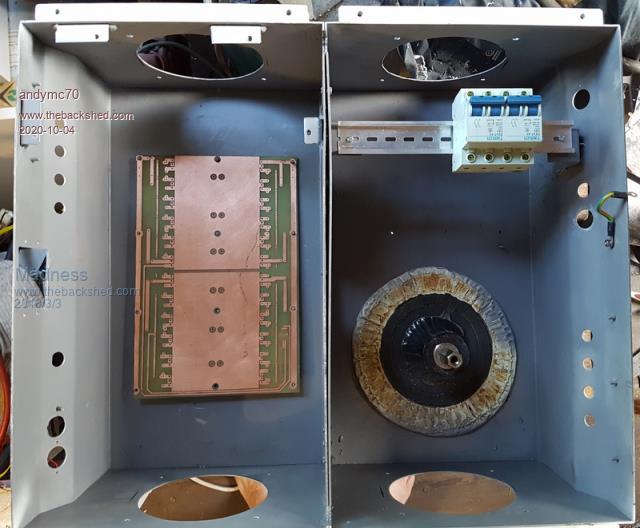 Thanks Andy |
||||
Madness Guru Joined: 08/10/2011 Location: AustraliaPosts: 2498 |
1 is a switch 2 is a fuse 3 is a 63A AC circuit breaker That is my original build, 1 and 2 have since been replaced with a 80A DC breaker. 80A Does seem on the light side but it has never tripped with normal and heavy use. The reason for using 80A is it will trip faster if you have a major failure. I had quite few of those in the early days and with a 200A fuse the circuit board was always badly damaged if things went wrong. With a 80A breaker MOSFETs can fail and trip the breaker before tracks get blown off the PCB. As mentioned above that was in the early days before using Totem Pole drivers. My Inverter has now run for over 3 years without a hiccup using EG8010 chip. I use 140MM fans they can run up to 100% especially when back charging at 100A for a few hours. I would not use anything smaller. Most of the time the fans are not running and natural convection is sufficient even here in Qld. The AC output from the Inverter in mine goes through the 63A breaker to a 63A Breaker/Change over switch in the AC switch board. I have done this to allow having a second inverter wired up ready to be turned on. The change over will only allow one Inverter to be connected. The Toroid holder in the photo above is not in it's original position, I ground off the original and welded in a new bolt where I needed it. There is about 5MM clearance between the Toroid and the fan. There are only 10 types of people in the world: those who understand binary, and those who don't. |
||||
| Clockmanfr Guru Joined: 23/10/2015 Location: FrancePosts: 427 |
Try this .....  or this ..... BlkEnclosure1.pdf Everything is possible, just give me time. 3 HughP's 3.7m Wind T's (14 years). 5kW PV on 3 Trackers, (10 yrs). 21kW PV AC coupled SH GTI's. OzInverter created Grid. 1300ah 48v. |
||||
| andymc70 Regular Member Joined: 30/06/2019 Location: AustraliaPosts: 42 |
hello I have a couple of questions for the nanoboard. R30 Bom says 6.8k 1/4w, where as PCB is 10k shown in pic. 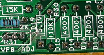 Also R21 is 470 on BOM and 1k on PCB. 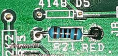 Also i am wondering which is positive the square or circle for the diodes and caps. Thanks Andy |
||||
| andymc70 Regular Member Joined: 30/06/2019 Location: AustraliaPosts: 42 |
Hello The AC EMI filters, i was only able to save 2 of 7 amp ones from the aeroshape. I wondering what size filters will i need to get or will the 2 work. Also wondering do i need a reset and cap charge buttons, if so what are people using. If not what do i need to turn the inverter on with. I have completed the choke, will do picture later, still waiting for AUSPOST for heatshrink for the primary wiring, 3 weeks now from sydney. Also i remember during trade school [30 YEARS AGO] we use to clean off our solder joints with alcohol and wipe it off with a product that was like a tissue paper sheet. I can not remember what they where called. I trying to clean my joints better. Thanks Andy |
||||
| Madness Guru Joined: 08/10/2011 Location: AustraliaPosts: 2498 |
Metho and a toothbrush work fine for cleaning flux off the PCB. 2 X 7A is not much over 3KW, I may have some of the bigger filters. There are only 10 types of people in the world: those who understand binary, and those who don't. |
||||
| Warpspeed Guru Joined: 09/08/2007 Location: AustraliaPosts: 4406 |
Metho and a toothbrush work fine. Isopropyl alcohol and a toothbrush works fine too. What works much better than either is a 50%/50% mixture of metho and isopropyl. I have no idea why a mixture of both works better than either by itself, but it sure does ! Cheers, �Tony. |
||||
| poida Guru Joined: 02/02/2017 Location: AustraliaPosts: 1389 |
D5, D14 etc. pictured there has the band marked on the silkscreen and so just line up the diodes to match the band. The line is negative for the caps. Just check a couple and see if the pin next to the line marking is connected to ground. Nearly all caps are negative to ground. The two charge pump caps C1 and C7 are not connected to ground via either pin. R21 is just setting the current for the over current trigger LED so anything that lights the LED with a 5V supply will do. 470R and 5V will be 10.6 mA and a good match for most LEDs wronger than a phone book full of wrong phone numbers |
||||
| andymc70 Regular Member Joined: 30/06/2019 Location: AustraliaPosts: 42 |
Sorry things have been progressing slowly due to being back at work. I have completed 95% of the control board and about to test it further. I have tested without the nano's and chips. All volts seem correct. Although the 12v is only 11.94v should i be concerned. Is there any order i should insert the chips to test the rest of the of the control board? Also i have started to program the nano's from POIDA post. Just want to confirm that the run/stop switch is a normal on/off switch. Also i have a 16x2 LCD wondering if i can use this instead of the 20x4, i will to need to buy I2C module add on and if i can not use the 16x2 then i will get the 20x4 with the add on. More questions to come. Thanks Andy |
||||
| poida Guru Joined: 02/02/2017 Location: AustraliaPosts: 1389 |
Andy: I would not bother with a 16 x 2 LCD. I would have to change the nano2 code to suit and I don't want to spend the time on that. sorry. (wife wants me to complete the home garden watering system that will drive eleven different water circuits. There will be a iphone app to drive it too. And the Eltek project(s)..) Just get a few 20 x 4 LCD from aliexpress, get those without I2C since they might be a bit cheaper, or get them with I2C anyway and use the nano_to_I2C LCD code I have. Next, yes, if you use nano2_5....continuous_on_off.. code then it will expect a normal toggle switch, single pole, single throw, on or off sort of thing. This takes a 5V signal and you can drive it from an external control system if you need. It is pulled down to ground to run the inverter and when you want to stop it, open the switch and let it float to 5V. 11.94V is really about as close to 12V as you can get. All things will work fine. 12V is used to drive the fans and feed the 5V regulator that then drives both nanos and other things. The 15V supply is used for the gate drive ICs, ultimately driving the gates 0 and 15V which is a good amount of gate drive voltage. I used 3 x 1N4007 diodes in series to give me the 12V (or near enough) in place of a 12V regulator. These 3 voltages are not super critical. (and your DVM might be a bit out too...who knows) when the time comes to fire up the inverter post here and I will talk you through a few tests. wronger than a phone book full of wrong phone numbers |
||||
| andymc70 Regular Member Joined: 30/06/2019 Location: AustraliaPosts: 42 |
Thanks Peter. I have ordered the 20x4 lcd, see how long that takes to get here. I paid a bit more to get it here before xmas. Am I correct to say that their are 3 ways to program NANO2 and depending what you like. I was going to try the nano2_5_ac_current_sensor_continuous_on_off_control_softserial version. Just wondering what sort of current sensor do I need to make it work. Also just for some education I really don't understand serial port or serial to parallel. I like to know a little bit more about this. Also just for some education. I am assuming your using the diodes to drop the voltage, so around 1 volt each diode. If this is correct, just wondering why a voltage divider is not used? Also what is a DVM? Andy |
||||
| poida Guru Joined: 02/02/2017 Location: AustraliaPosts: 1389 |
A DVM is a digital voltmeter. A voltage divider would not work in this application. the 15V -> 12V needs to supply enough current to drive one or both fans plus the logic and the LCD. I would guess at least 1 Amp at 15V when both fans are howling. I use nano2_5_ac_current_sensor_continuous_on_off_control_softserial in both of the builds at home. When using this firmware, the serial data comes out of pin A4 which is connected to the 4 pin header of the I2C. Pin 4 is not used. Only pins 1,2,3 which are ground,5V, TX are needed with the serial LCD. To get an idea how the serial port LCD etc works spend some time playing with it. program a nano with a simple sketch that sends a bit of text out it's serial port (pin D1) at 9600 baud. This will be the test source of serial data. Then you build the serial LCD, and eventually you will work out which wires do what. once you get it working. Current sensors are not needed to get the inverter running. I would put it on the nice to have list, to be done later. what I call the serial LCD is a 20 x 4 character LCD (using the very common driver chip) connected to and powered by an arduino nano. The end result is a 2 part device that has 3 wires you need to connect to the data source. (ground, 5V and data). It runs at 9600 baud. There is a very simple protocol that accepts letters and numbers except '$' which is a control character used to move the cursor to the top left of the screen. The reason I like the serial data connection, compared with I2C is the I2C pins are very sensitive to EMI. When setting a pin to digital output and then driving it at 9600 baud the nano no longer gets EMI that upsets it's operation. So, you take a nano and about 10 different coloured wires and the 20 x 4 LCD. Find a pdf manual for the LCD showing the pinout. There are 16 pins in a row. We need to use 4 data pins, 5V, ground, RS and E. This is 6 pins for data and control plus supply/ground. We use maybe nano pins D8,9,10,11,12,13 to drive the LCD but we can use nearly any pins except D0 and D1 which is used for the nano on-board serial port. I also choose to the software serial for the input to the serial LCD so it is listening on pin D4. The below code is what is loaded into the nano that connects directly to the LCD. I have edited it to make it as small as possible. #include <LiquidCrystal.h> #include <SoftwareSerial.h> SoftwareSerial sSerial(4, 5); // RX, TX LiquidCrystal lcd(12, 11, 7,8,9,10); //LiquidCrystal lcd(rs, en, d4, d5, d6, d7); void setup() { sSerial.begin(9600); lcd.begin(20,4); lcd.clear(); lcd.setCursor(0,0);lcd.print("Serial -> LCD"); lcd.setCursor(0,1);lcd.print("pin D4 for RX"); lcd.setCursor(0,2);lcd.print("9600 baud"); lcd.setCursor(0,3);lcd.print("$,~ ctl"); } void loop() { int c; while (sSerial.available()) { c = sSerial.read(); if (c == '$') lcd.setCursor(0,0); else lcd.write(c); } } wronger than a phone book full of wrong phone numbers |
||||
