
|
|
Forum Index : Electronics : Time for a new Warpinverter build
| Author | Message | ||||
| Warpspeed Guru Joined: 09/08/2007 Location: AustraliaPosts: 4406 |
Yes, the Warpverter is completely bi directional for current flow. A grid tie inverter will send power back into the batteries whenever solar power exceeds the load on the system. That needs some care if overcharging is to be avoided, but there are ways around that. This bi directionality also works for highly reactive loads. Very high out of phase reactive current can surge back and forth without any problems at all. Excellent for starting large induction motors !! Cheers, �Tony. |
||||
| rogerdw Guru Joined: 22/10/2019 Location: AustraliaPosts: 904 |
Ahh, that is great news. Obviously it's a long way in the future but still very nice to know. Will let some ideas percolate. Thank you. Cheers, Roger |
||||
| Clockmanfr Guru Joined: 23/10/2015 Location: FrancePosts: 437 |
rogerdw, I have not built a 'Warpspeed Inverter' yet. I am watching you with great interest. I just do the OzInverters. AC COUPLING , or Back charging the batteries I have not used a HF, High Frequency, GTI because second hand old heavy toroidal types are easily obtainable and very cheap, plus you get to use the GTI internal MPPT . 'Oztules' and others have experimented with HF types and do not find any real difficulties. I have always seen AC coupling as the way forward, rather than just DC and many expensive charge controllers. I originally bought a very expensive, so called Rolls Royce of commercial Inverters, 48vdc to 240vac, Firstly it couldn't do the specified 6kW and constantly only do 4.2kW, secondly it needed a lot of expensive propriety ancillary control equipment to function and back charge the batteries correctly. And thirdly It raised the 240vac HZ frequency from 50HZ to 60HZ and domestic equipment failed. It went back, and the company put a gagging order on me not to talk about there crap toy Inverter. 'Oztules' stepped in, and like me he wanted a true and real Inverter that would do the AC coupling using a H bridge design without all the fuss. Our Mantra .... KEEP IT SIMPLE, MAKE IT ROBUST, and importantly MAKE IT COST EFFECTIVE. A very cost effective solution for handling that 19kW of power from the PV array, is to use what is called 'AC Coupling'. Houses that you see around the World with PV on the roofs will be using GTI's, (Grid Tied Inverters) that take the PV dc output and change it to ac and feed it back into the Mains Utilities Grid for that Country. These GTI's are slave machines and need to see the correct ac voltage and the correct HZ frequency, so to get there internal electronics/transformer to operate before they will feed into the Grid a few volts over the Mains Utilities supplied voltage. There are many Good Quality GTI's available second hand, i use fleebay etc, and i prefer GTI's with a toroid transformer, see below photo of previously used SMA's........ . 150 to 300 Euros each. The 48vdc OzInverter creates a very stable 240vac or 120vac at a stable 50H or 60HZ and therefore allows 'AC Coupling' the GTI's back charge through the OzInverter to the battery bank. Three methods of controlling the back charging from GTI's is possible for 'AC Coupling'. A. Use the Internal codes/settings in the GTI's to sequential shut down when a specified ac output voltage is reached. This works reasonably well with my system as some installations GTI,s are up to 400 meters away from the OzInverter and batteries, and the batteries do push back slightly, but this depends on the cable voltage sag. B. Use dc voltage comparators circuit to shut down the GTI ac side with a relay when the DC battery voltage rises above a charging rate voltage. But you will need to run a data cable to all your installations, and again allow for voltage sag. C. Use PWM dc controllers that are connected directly to the 48vdc battery bank. These Diversion controllers, (Morningstar Tristar PWM at about 200 Euros each), will regulate the charging and any excess power when the batteries are full and will dump/divert to other permanently connected sources, ie, Air Heaters 2kW each or Hot water heaters, underfloor electric heating. The above are a cost effective and very reliable system, A is used most and C is my guaranteed safety system. Where i do not have access to the GTI internals, then i use B. For a 19kW Array I prefer using 2off 1.7kW & 4off 2.5kW GTI's for 14kW, and using DC Charge controllers for the 5kW as these can gently finish charging that precious 48vdc battery bank. I trust this information helps. 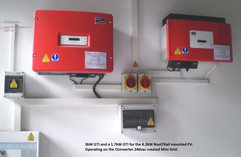 Edited 2021-02-15 19:25 by Clockmanfr Everything is possible, just give me time. 3 HughP's 3.7m Wind T's (14 years). 5kW PV on 3 Trackers, (10 yrs). 21kW PV AC coupled SH GTI's. OzInverter created Grid. 1300ah 48v. |
||||
| rogerdw Guru Joined: 22/10/2019 Location: AustraliaPosts: 904 |
Gulp, the pressure's on. Haha. I had read that you were keen on the older LF inverters and I wondered which were the ones with toroidal transformers, other than our much loved AeroSharps. I believe older 'Inspire' units did ... and seeing your pix here of the Sunny Boy SMA units, I assume they also use toroids. Have spent a lot of time looking for technical details of them, but haven't been able to find any internal pictures below their circuit boards. Can you give me some model numbers of LF inverters so I can keep my eyes open. I understand any SMA inverter with 'TL' in the model number stands for 'transformerless', so I know to avoid them. I actually picked up a faulty 5kW TL SMA a few weeks ago for $25 and (as a long time elect tech) was actually quite impressed with the build quality and mechanical design. No idea if they are actually any good, but I like how they are built. There was also an SMA 10kW Tripower unit there for $25, but they are 3 phase and it was big ... and I had a car full of AeroSharps already.  Yes, sounded like quite a saga. I have spent a lot of time over on the fieldlines forum reading up on all the background ... been quite a journey for all you guys. Haha, you're answering questions I was going to ask somewhere in the future once I'd made some progress on my build ... but seeing you've mentioned it ... I see you're using the old GTI's to provide power ... effectively seperate solar systems on your seperate houses ... but using the output from your Ozinverter as your own mini-grid for them all ... ... so I'm assuming you still have to have some conventional charge controllers charging the Ozinverter's battery bank? Anyway, thank you very much for all your detail, I hope I can retain enough to make the right choices once I reach that stage. Cheers, Roger |
||||
| Clockmanfr Guru Joined: 23/10/2015 Location: FrancePosts: 437 |
Can you give me some model numbers of LF inverters so I can keep my eyes open. Here are 2 PDF docs for SMA model SB's, but in general for a toroid when you pick it up it should be heavy, normally around 25kg to 35kg. A normal toroid type SMA SB's will normally push out up to 254 to 256vac. And Yes those SB's were nice made and worked well, but they are old tech so easy cheap to get hold of. The other PDF is for the plug in Bluetooth control board you plug in, SMA bluetooth is bad so you do need a powerful bluetooth sender in your laptop like the 'SENA UD100' to then re-set the SMA SB internal settings for sequential shutting down. I just have a couple of boards and plug them in and reset and set, then i remove the board and off to another GTI. I only have 5kW of PV going through a MIDNITE 200, and a MPPT TRISTAR DC charge controllers, but they are very expensive controllers but good for finish charging. Most of the battery charging is with the AC coupling 14kW of PV feeding back from those GTI's running the 240vac circuits and back feeding through the 'OzInverter' to the batteries. Hence i reset the SMA SB's internal settings to just a few seconds on and off, and sequential GTI shut down voltages from 242vac 243, 244, 245, 246 and 247vac. PLEASE NOTE, GTI's are best when they are smaller units, i no longer recommend anything over 2.5kW, why?, because when they are big they constantly cycle on off as they overfeed and push the AC voltage high. Yes the 'Aerosharps' are reasonable quality according to 'Oztules'. Good luck and enjoy your build. SB-OffGrid-TI-en-41W.pdf SBuseforSISIPVusage.pdf SMABTPB-IEN112112.pdf Everything is possible, just give me time. 3 HughP's 3.7m Wind T's (14 years). 5kW PV on 3 Trackers, (10 yrs). 21kW PV AC coupled SH GTI's. OzInverter created Grid. 1300ah 48v. |
||||
| rogerdw Guru Joined: 22/10/2019 Location: AustraliaPosts: 904 |
Thanks for all the extra detail Clockman. Until recently I didn't realise that SMA had made inverters with toroidal transformers ... and now that I do, I am wondering why they are never mentioned as possible donors to be rewound for Ozinverters or Warpinverters. The SMA inverter that I picked up recently was of the later HF transformerless type. I really only bought it coz it was $25 and I figured I'd get my money's worth just pulling it apart and seeing how it ticked ... and maybe some bits I could use. I'm not even certain I will really need additional inverters to my Warpinverter system ... I think my main reason for asking the questions is because I know I will need battery charging ... and wondered if that can be done with an additional inverter alone ... ... or whether I will still need a conventional MPPT charge controller to look after the batteries. If that is the case, there have been a number of designs here on the back shed in recent times. I hadn't made plans too far ahead ... still have to wind my transformers and work out the drive side. Thanks, I had picked that up and it does make sense ... though I was surprised when I read your pdf's, that SMA recommend that additional inverters (to the Sunny Island) should not be bigger than twice the size of the Island's power. In fact that was all new to me ... while I had heard the name Sunny Island, I didn't realise they could be used as a 'mini-grid' with additional inverters ... I thought they were (just another) pv inverter! Thanks again for all these details, I'm slowly getting more of the bigger picture. Cheers, Roger |
||||
Haxby Guru Joined: 07/07/2008 Location: AustraliaPosts: 423 |
The aerosharp range, from 1kw, 1.5kw, 2kw, 3kw all have the same diameter copper wire that is not potted in, so they lend themselves well to unwinding and reusing the copper. Other brands might be a bit of a hit-and -miss affair in terms of copper wire thickness, potted core, etc. Not sure why other brands are not too popular in this forum, maybe it's because Aero-sharps were not considered very reliable by those in the industry so there may be more faulty ones out there? I've taken apart a few now, and I'm very happy with their quality. Since I haven't repaired any, maybe they all share a common failure point. |
||||
| rogerdw Guru Joined: 22/10/2019 Location: AustraliaPosts: 904 |
I've only unwound three 3kW and one 1.5kW AeroSharp inverters ... and I do recall being surprised that the 1.5kW used 1.8mm wire for the 92V winding ... while the others were mostly all 1.6mm. My collection also inludes some 2kW units, but I haven't actually stripped any of their windings yet. I agree that they appear well made and I'm not even sure what was wrong with the ones I dismantled. They all came from a solar inverter repair co ... though I suspect the company is only called that to attract people with solar issues ... ... then they just sell them new inverters.  One of the 3kW units had shorted turns on the toroid ... and I reckon one of the others had a faulty IGBT module. The 5kW SMA I mentioned above is on another level again as far as build goes ... no scrimping on quality of parts, fittings and connectors ... ... 10 minutes and you can have it completely stripped down to minimum components ... And maybe 15 mins to completely reassemble it again ... but bear in mind this is a much later transformerless model. Cheers, Roger |
||||
| rogerdw Guru Joined: 22/10/2019 Location: AustraliaPosts: 904 |
Okay ... for those of you wondering if I've given up or not!!! I'll upload some photos, that'll save some typing I've taken the lead from Klaus and 'frackers' and am using a hoop through the core rather than small reels. First photo is of some tools I made to help with the winding. The one on the left is shaped so it sits in the slot of the hoop to help open it, plus push the wire around as I load the hoop. Works great, I seemed to have fluked the shape so it stays in the slot and I just push the wire around and into the hoop which closes up behind it. The middle tool has a small roller on the end so I can roll the windings into place if they are raised too high for when I wasn't careful enough ... and the last one is just a poker/push stick for shaping the windings and getting them closer together. They're all made out of an old plastic cutting board I've used in the workshop for 20 years or so. 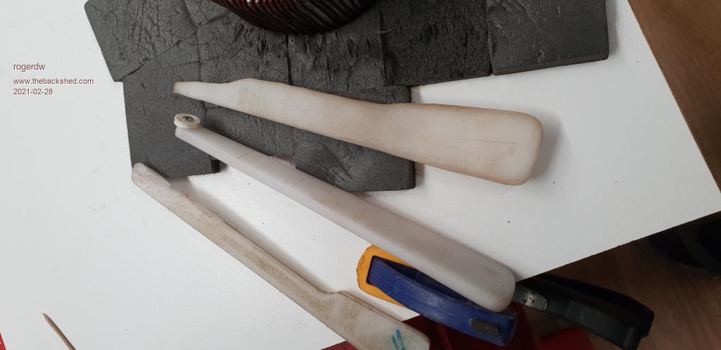 The hoop is an old kids hula hoop which I slit using a plastic cutting disc in my Dremel. The hoop has an OD of about 19mm ... and I am surprised just how much wire can fit inside. Using some 1.7mm wire from an old 3kW AeroSharp toroid which was 52mtrs long ... all of it wound easily inside the hoop. I have no doubt I could get at least another 50 mtrs inside it if I needed to. It is 670mm diameter ... so 2.1mtrs of wire per turn Here I'm loading the hoop with the 52mtrs. This will be the first winding on my #4 transformer ... 2 windings of 169 turns. 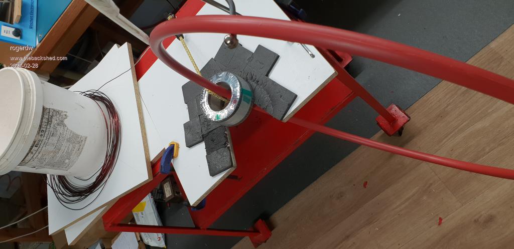 Not sure why the site is rotating my pictures. Anyone know how to fix that? edit: Mmmm ... and I've tried to add more photos to this post and an additional post ... but the images won't show at all. Edited 2021-02-28 20:40 by rogerdw Cheers, Roger |
||||
| Murphy's friend Guru Joined: 04/10/2019 Location: AustraliaPosts: 671 |
Looking good and a wise choice to start with the small one - i started with the big one  . .You might consider sitting the core onto something smooth like you table surface when you wind it as it will slide much easier around. I wound the big double core on a curved support (so I could look into its *horizontal* hole). I found that way safer after it nearly slid off the table while winding it like in your pic. Its *very* heavy even when empty and you won't be able to catch it should it slide off the table. The smaller, narrower, cores are fine to wind as you show. I like your 'hoop', great find, and your wire loading tool looks a lot smarter than that wood dowel I used. When sticking on the paper radial marks to align the wire you only need that on the top as you can't see the bottom of the core anyway. Perhaps spaced lines around the outside of the core help to keep the wire straight. The roller on your 'pushing' tool might be a nuisance, I would have cut just a groove at the tip to exert maximum leverage. Have fun, I hope you have strong hands - you certainly will have them after this job |
||||
| rogerdw Guru Joined: 22/10/2019 Location: AustraliaPosts: 904 |
Thank you ... I'm not always good at listening to advice, but glad I did in this case. Already the difference between my first transformer (#4) and the second one (#3) has been an improvement. Yeah, I'm not sure why I chose this way ... but it seems to work ok for me .... but I'll certainly consider changing for the larger transformers. The black foam is relatively soft, so they don't slide too well ... which suits me fine so far. I have fitted an ocky strap through the core to help prevent it sliding off the front if I get too physical. Yeah I did exactly that ... just one on the top and one around the outside to help keep them vertical. The roller tool really needs two hands to control it to work the best as it can roll too freely ... which is a bit tricky when you also need a third hand to keep the wire tight. I've taken up wrapping my thumbs with masking tape before I put on my gloves ... but it's my middle finger that's suffering at present. I'll have to change fingers for the next layer. I know you said you were able to sit down to wind yours, but I've had to stand to do the job here ... and particularly for the first one ... I ended up with jelly legs from squatting down to get the wire underneath properly ... then standing up to complete the turn. The first few days were a bit painful ... but my legs seem used to it now. I'm actually enjoying the winding ... in a perverse sort of way.  Looks like my images still won't show. Dunno what's up there. Cheers, Roger |
||||
| rogerdw Guru Joined: 22/10/2019 Location: AustraliaPosts: 904 |
#4 Transformer nearly ready for the secondary 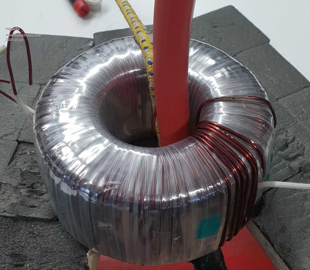 #3 Transformer with template fitted as a winding guide. It helped a lot. 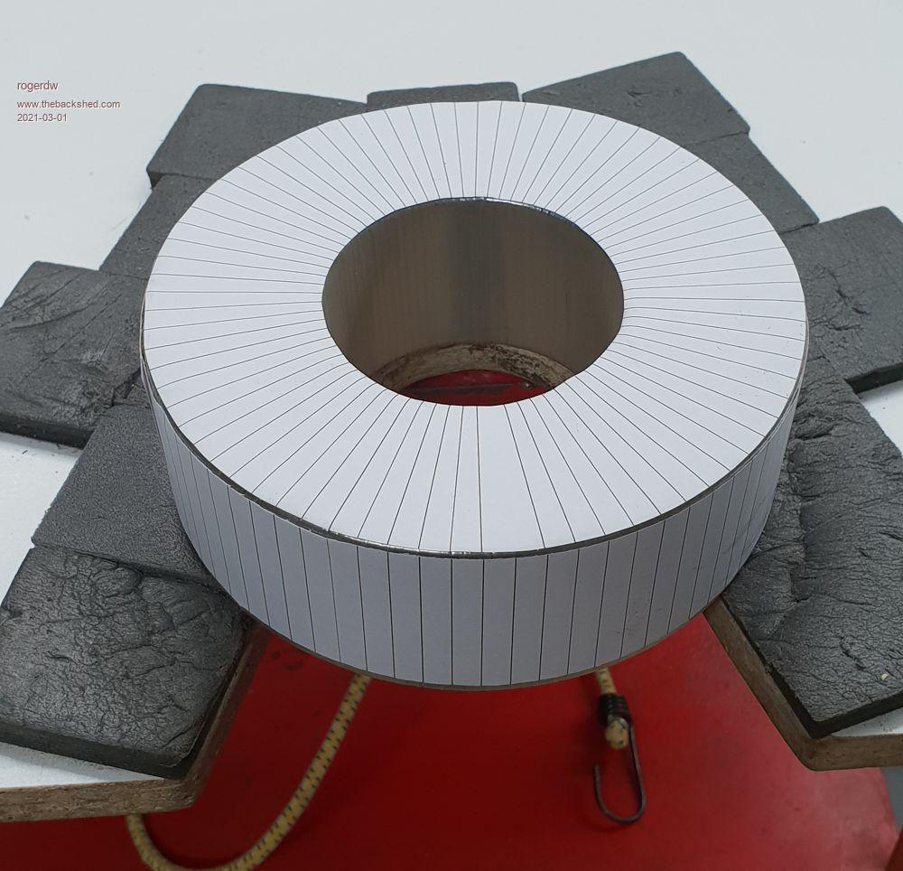 Cheers, Roger |
||||
| rogerdw Guru Joined: 22/10/2019 Location: AustraliaPosts: 904 |
Two layers done and two to go on #3 Tx. 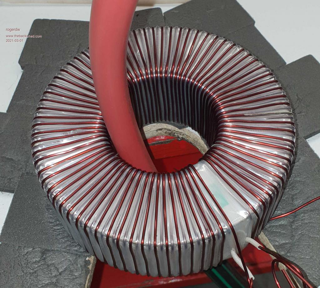 This shows the support for the hoop. Just pulled some scrap out of the junk heap and screwed it to the base board ... and bent it back enough to 'hang' the hoop in the right spot. 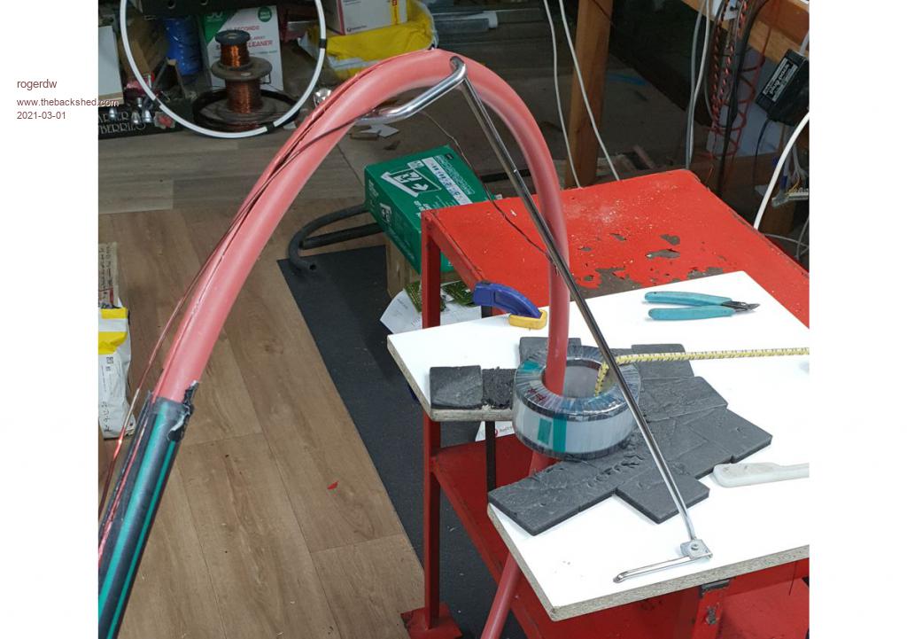 Cheers, Roger |
||||
| Haxby Guru Joined: 07/07/2008 Location: AustraliaPosts: 423 |
Great work! Very neat! |
||||
| Murphy's friend Guru Joined: 04/10/2019 Location: AustraliaPosts: 671 |
Yes, very neat indeed - much neater than mine was done, your wire spacing is the neatest I have seen on this forum. I see you did not use a rounded cheek spacers on the cores, perhaps that is the reason your fingers are sore . I did not use any gloves nor masking tape on the fingers .Re doing it standing up, you would not even consider it if you had my bad back. I used one of those B&D workbenches which was just the right sitting height, it even had a foot rest. Good idea that hoop support with your big hula hoop, my smaller hoop was OK without that refinement. You might remember seeing a picture of that split PVC tubing I hammered into the hole after each layer but before applying the mylar. The PVC outside was waxed, the epoxy I poured down there securely locked the layer in place while it was pressed against the hole. This allowed only one layer per day but I think was very worth while. My toroid transformers are very quiet, the only hum comes from the choke if the two halves are not clamped very very tight. |
||||
| rogerdw Guru Joined: 22/10/2019 Location: AustraliaPosts: 904 |
Thanks for the compliments Haxby and Murph, that is very encouraging. I was only planning on using the rounded cheek spacers on the largest #1 transformer, where I'll be fitting a 5mm spacer between the core and the first winding ... though now I can see it probably would have been worthwhile doing it for all of them. ... plus I'm a bit of a softy just doing technical work all the time with rarely any hard physical stuff. Maybe this'll at least toughen up my fingers. Sorry to hear you have back troubles, that would certainly take the fun out of it. I did play around with different ideas, but being pretty tall I find it hard seeing underneath and then up and over the top ... so I'll persevere with the standing method. I suppose it's no different to all those in the gym doing all sorts of exercises ... at least I can see something for my efforts. Yeah, I was really pleased how the hoop stand worked out. Early in the planning I was thinking about all sorts of complicated ideas of supporting it with rollers and all that stuff ... but the way its turned out, I can still hold the wire taut with one hand and easily spin the hoop around with the other. I do recall seeing your method for keeping the inner windings tight, which is an excellent idea ... especially when loading the epoxy and keeping that to a minimum. I did have a discussion earlier in this thread with Tony about using epoxy or not ... and I decided to go without. That may turn around and bite me on the butt ... but I'm willing to take a chance. It's another reason my fingers are copping a hammering because I'm making a really concerted effort to keep it tight all the way around and not letting up anywhere. The inverter will be housed in my shed adjacent to my workshop ... and a long way from the house ... so unless it's really bad, the idea of a bit of hum is not worrying me too much ... ... plus I can always have them dipped in transformer varnish if it does become an issue. My lovely wife came home tonight with a bundle of finger tip protectors ... like little rubber thimbles they used to use for counting money etc. I'll give them a whirl on my sensitive fingers. Sound like a real girl now. Cheers, Roger |
||||
| rogerdw Guru Joined: 22/10/2019 Location: AustraliaPosts: 904 |
Okay, so just need several layers of insulation and the #3 transformer primary is finished. Four windings of 74 turns each. Then it needs 6 x 42 turns of 1.8mm wire for the secondary ... or equivalent. You can see my new fingertip savers. They certainly help, but my fingers need a rest for a while. 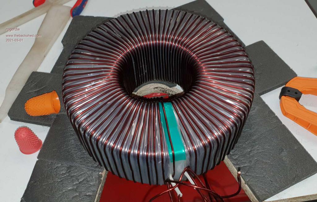 Cheers, Roger |
||||
| Warpspeed Guru Joined: 09/08/2007 Location: AustraliaPosts: 4406 |
Wow, that is a superb effort, it looks like a machine produced that, its so precise. I must confess I chickened out of toroid winding, I have done too much of it in the past, and age is starting to catch up to me. Cheers, �Tony. |
||||
| rogerdw Guru Joined: 22/10/2019 Location: AustraliaPosts: 904 |
Haha Tony, I am a machine But seriously, thanks for the compliments. As you know I've been dragging my feet for years but now that I've worked out a system for winding, I am enthusiastic. Should be even better using new wire with no kinks ... looking forward to that. Cheers, Roger |
||||
| rogerdw Guru Joined: 22/10/2019 Location: AustraliaPosts: 904 |
I'm still slogging along and making slow progress. I just picked up another 3kW AeroSharp and have unwound the transformer ready to wind #2 Tx (second biggest) transformer. Something that I do not recall having seen mentioned anywhere in all the threads on the Ozinverter and Warpinverter is that there can be two quite different size 3kW toroids. As you'll see in the photos, some have an OD of 205mm while others are only 185mm OD. The ID and height are the same at 100mm ID and 70mm high. Obviously that makes quite a difference for the cross sectional area ... and for me, if I'm going to go to all this trouble winding transformers, I might as well go as big as possible. I've got two of each type ... and the smaller one has a paper label on a blue plastic tape that's wrapped all the way around and the larger has an off white paper label. The tx on the right is one of the larger cores and has been unwound now. 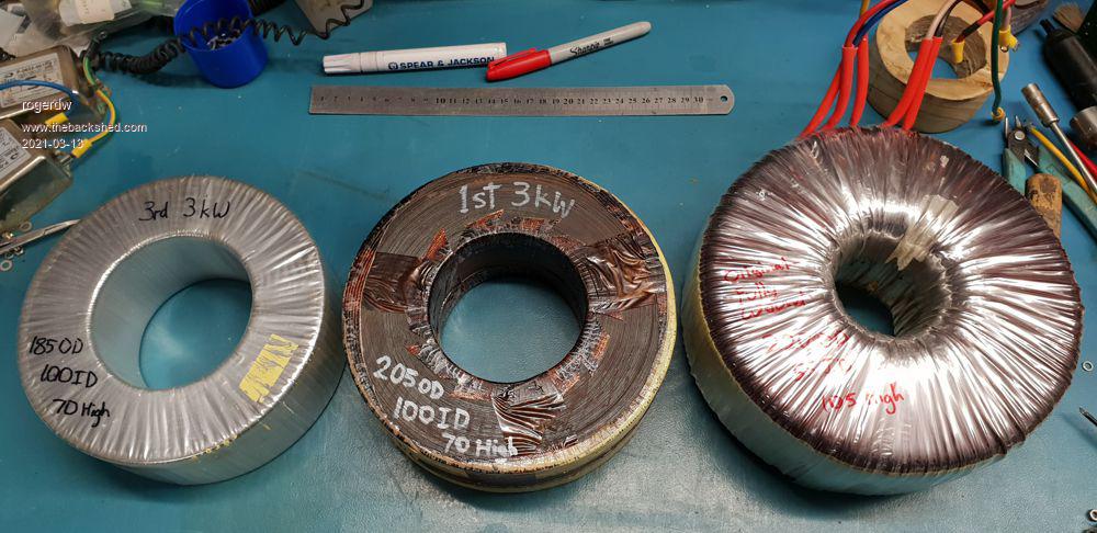 This is the label from the smaller toroids stuck on blue plastic tape. 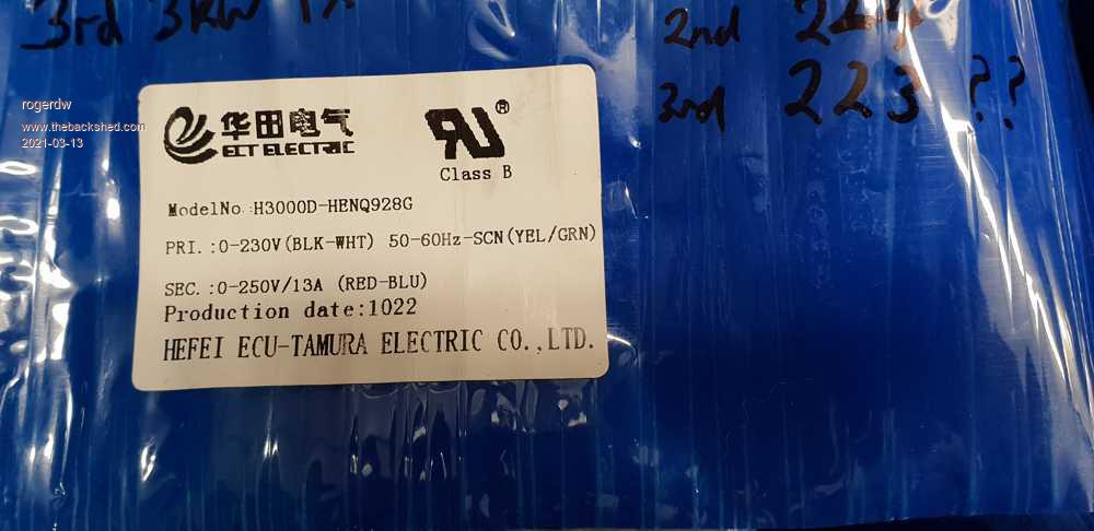 And this from the larger toroid made by Eaglerise Electric. These are more of a pain to unwind as they are actually wound with three wires being wrapped at the same time ... and invariably one wire gets trapped under an adjacent winding and you have to be pretty rough to extract them. I do worry about damage to the insulation in this case. 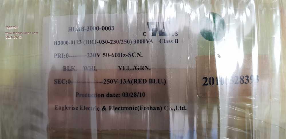 Cheers, Roger |
||||
| The Back Shed's forum code is written, and hosted, in Australia. | © JAQ Software 2025 |
