Notice. New forum software under development. It's going to miss a few functions and look a bit ugly for a while, but I'm working on it full time now as the old forum was too unstable. Couple days, all good. If you notice any issues, please contact me.
renewableMark Guru Joined: 09/12/2017 Location: AustraliaPosts: 1678
Posted: 10:22am 18 Mar 2021
Copy link to clipboard
Print this post
nahhhh I don't care mate, Klaus, Tony, any one of us would have told you that anyway.
Where did you get that tape from?
I seem to remember it wasn't cheap for what you got, and it's hard to get. I think they were about the size of a roll of electrical tape. From memory it needed three or four rolls to do a double stacked 3kw core set
You just need to not be a cheapskate when making these, just get what you need the end product will be still far cheaper than a commercial unit.
Remember that tape is insulation, VERY IMPORTANT!!! Edited 2021-03-18 20:27 by renewableMarkCheers Caveman Mark Off grid eastern Melb
rogerdw Guru Joined: 22/10/2019 Location: AustraliaPosts: 904
Posted: 11:34am 18 Mar 2021
Copy link to clipboard
Print this post
Yes, mine were about the size of a roll of electrical tape too, I was expecting much bigger.
My 3rd biggest transformer has 7 secondary windings in 7 layers and with mylar underneath and between each layer. That's a lotta tape! And the big one is going to use twice the length.
I am very happy with the condition of the stuff I've pulled off most of the transformers ... though some still had glue from tape stuck on it and the stuff from the burnt transformer was pretty discoloured and brittle, hence chucked out.
I'm also confident with the wire too as with the way it's wound there is virtually no winding touching another winding anywhere ... without mylar in between. I'm actually astounded that is possible.
And from the jumbled mess of some of the windings I've dismantled, I'm surprised they run more than 5 minutes the way they've been wound ... so their original insulation must be some super dooper stuff!
I did buy a roll of new 1.8mm wire (7kg) and coz I'm not sure just how much the big transformer will need, I am saving it for that. Perhaps I'll buy new insulation for that one as well just to be on the safe side.
Normally I would never have considered using second hand wire ... but all you guys have been using it for years with the Ozinverters and getting away with it ... so I figured I'd take a chance with the 3 smaller transformers.
They're not really that easy to wind ... but if I had to rewind one it wouldn't be the end of the world. Plus if I do manage to pull it off, it will be awesome to tell the cc botherers that my inverter is built largely with scrap! Cheers, Roger
Warpspeed Guru Joined: 09/08/2007 Location: AustraliaPosts: 4406
Posted: 09:56pm 18 Mar 2021
Copy link to clipboard
Print this post
Its a character building exercise.Cheers, ĀTony.
rogerdw Guru Joined: 22/10/2019 Location: AustraliaPosts: 904
Posted: 01:22pm 19 Mar 2021
Copy link to clipboard
Print this post
Yes, something like that. I do feel a sense of achievement as it comes together so that part's good.
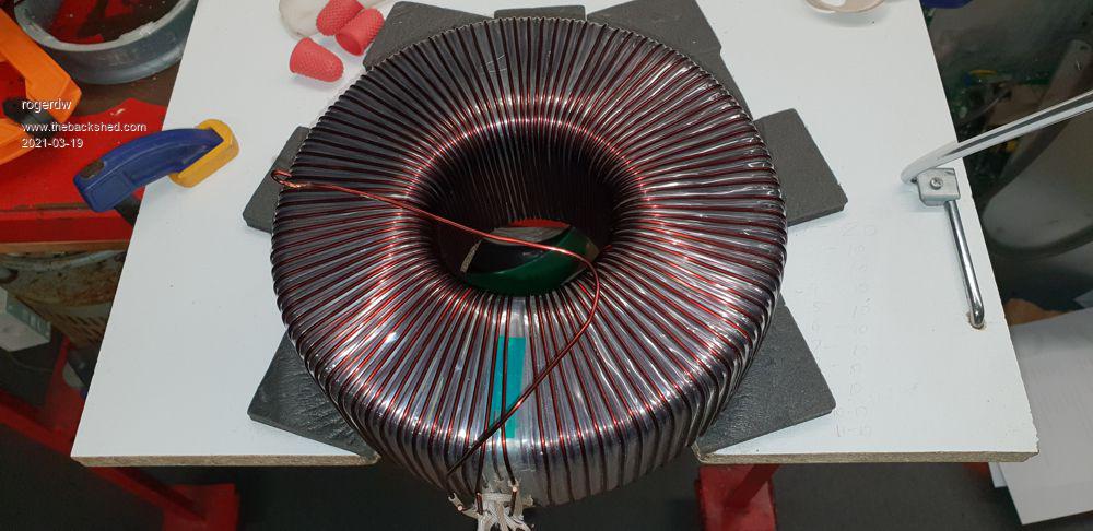
Well I finished the next two layers ... six down, one to go. Then the BIG one.
Must be divine intervention, but there was even less left over after these two layers ... 20cm was all that was left of 27.5 meters.
It's very handy to know because it will help me estimate just how much to load in my hoop for the next layer ... or anyone else that winds one similar for that matter.
The centre hole is down to 74mm and with a layer of mylar, another winding and a final lot of mylar it's going to be around 70mm total.
The primary needs 54 turns of 103A wire ... which has an OD of 7.2mm
The "Smaller Circles within a Larger Circle" calculator tells me I can fit 54 turns of 8.2mm cable ... so it will be tight, but should be doable.
Cheers, Roger
rogerdw Guru Joined: 22/10/2019 Location: AustraliaPosts: 904
Posted: 01:50pm 19 Mar 2021
Copy link to clipboard
Print this post
I mentioned in an earlier thread that the toroid can theoretically be wound without the wire physically touching another winding at any stage of the assembly ... which may sound like a pretty bold statement.
And while mine has turned out pretty neat, it would have a few adjacent wires in the centre of the hole that do touch ... though if I was super concerned I could spend a bit more time to space them more carefully so they do not touch.
Maybe I could wind a thick piece of fishing line between the wires to fill the gap and keep them apart.
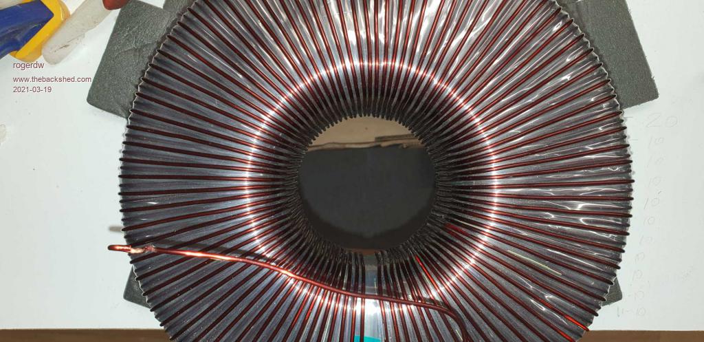
This picture shows the spacing of the wires through the centre.
I also mentioned earlier about the mylar taking up a lot of volume, particularly inside the hole.
Just to get a half overlap around the outside, actually creates four layers around the inside ... see pix
Cheers, Roger
Warpspeed Guru Joined: 09/08/2007 Location: AustraliaPosts: 4406
Posted: 08:49pm 19 Mar 2021
Copy link to clipboard
Print this post
Don't stress yourself Roger, there is only a volt or so difference between alternate turns, and the insulation on the wire is really excellent stuff.
The thick winding will go on easily. The circles within circles software assumes rigid perfect mathematically correct circles. The very fine multistranded wire with thermoplastic insulation is quite soft and easily deformable. If you put it in a vice, you can squash it flat fairly easily.
So where one turn touches another, the wire can deform slightly and the whole mess can be squeezed into a slightly smaller space than theoretically necessary. So if the software says it will fit, it will all fit on easily with space to spare for a big central mounting bolt.Cheers, ĀTony.
rogerdw Guru Joined: 22/10/2019 Location: AustraliaPosts: 904
Posted: 11:56pm 19 Mar 2021
Copy link to clipboard
Print this post
Nah, I'm not concerned at all ... it was really only in reference to my comments about how spaced out the wire is and that it could literally be wound without any adjacent wires touching at all.
And that is the reason I'm not fussed about using second hand mylar ... because mylar is barely needed anyway. Maybe between primary and secondary ... but the thicker wire will have even thicker insulation, so probably not 100% neccessary there either.
I'm usually a bit optomistic and can be caught out sometimes so that's encouraging to hear. Last thing I want to be doing is unwinding some layers to fit everything in!!!
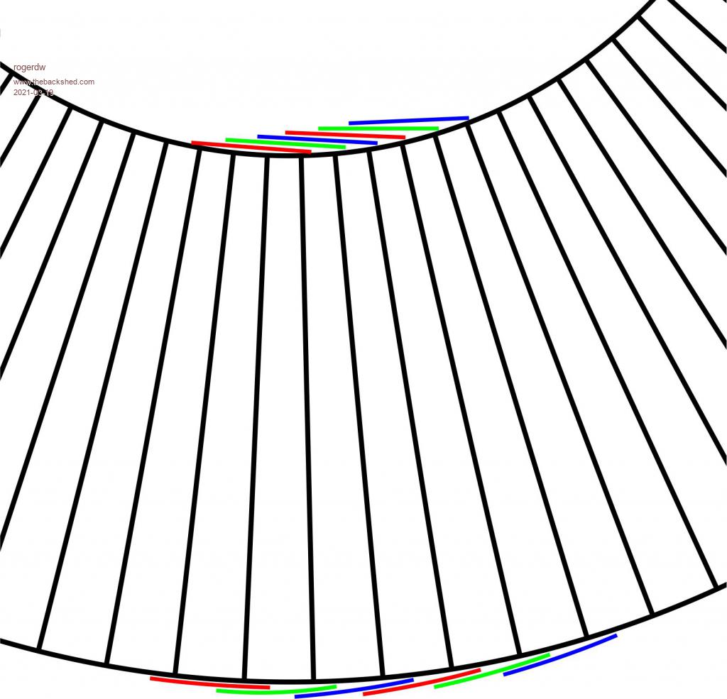
I had noticed in looking at the display of circles inside a circle that they make no great effort to space them optimally.
They place a full circle around the outside and then another inside that ... but make no effort to place the second lot into the grooves between the outer windings. I'm sure that would allow another turn or two if desperate.
I just tried using a graphics program to place that second layer into the grooves ... but you can only get 2 or three per layer to actually go in the groove because of the smaller diameter ... so I only managed to fit one extra circle.Cheers, Roger
Warpspeed Guru Joined: 09/08/2007 Location: AustraliaPosts: 4406
Posted: 02:02am 20 Mar 2021
Copy link to clipboard
Print this post
I tried something similar with a coffee tin lid, and a bag of big washers. You can shuffle things around, but basically you cannot gain very much by doing so.Cheers, ĀTony.
rogerdw Guru Joined: 22/10/2019 Location: AustraliaPosts: 904
Posted: 03:12am 20 Mar 2021
Copy link to clipboard
Print this post
Haha, we do think very much alike.
I think with the software version I could see what you were referring to earlier ... that with a little bit of squeezing and manipulation in places you could get a wire through where a solid tube simply would not fit.
In some spots it only needed a half a mm or so to fit a wire ... so I can see it being flexible enough to cope with that. Anyway I'm looking forward to that part of the exercise. Feels like it should be an easier part of the whole winding job.Cheers, Roger
Warpspeed Guru Joined: 09/08/2007 Location: AustraliaPosts: 4406
Posted: 05:10am 20 Mar 2021
Copy link to clipboard
Print this post
Definitely much easier. If the last couple of turns look tight, just stick a big screwdriver through the hole and wiggle it around. That will make room. But I doubt if you will even need to do that.Cheers, ĀTony.
rogerdw Guru Joined: 22/10/2019 Location: AustraliaPosts: 904
Posted: 01:36pm 20 Mar 2021
Copy link to clipboard
Print this post
Yep, plus a can of silicone spray and I'll be right.
I've finally wound the last secondary winding for #2 Tx so need to start planning for #1.Cheers, Roger
johnmc Senior Member Joined: 21/01/2011 Location: AustraliaPosts: 282
Posted: 11:14pm 20 Mar 2021
Copy link to clipboard
Print this post
Good day All
Very pleased to hear Klaus is OK .
I bought my tape from a electrical company in sydney ( can not remember the name) which was about 200mm in diaameter.
cheers johnjohnmc
rogerdw Guru Joined: 22/10/2019 Location: AustraliaPosts: 904
Posted: 04:42am 21 Mar 2021
Copy link to clipboard
Print this post
Hi John,
Yeah, the pictures I had seen were of quite large rolls and so when I finally found a place that sold it I expected them to be around that.
The ones I got were only about 50mm in diameter so I was a little disappointed.Cheers, Roger
rogerdw Guru Joined: 22/10/2019 Location: AustraliaPosts: 904
Posted: 02:04pm 11 Apr 2021
Copy link to clipboard
Print this post
There's not a lot to report but I should still update my log.
I've wound the first winding for each of the transformers #2, #3 and #4 and am starting on the big daddy #1.
I have two larger 3kW cores stripped and ready to work on. I plan remove at least 20mm from the centre ... from 100mm ID to 120mm to allow a 5mm spacer between the core and the secondary winding ... and allow my substantial secondary windings to fit.
The secondary will be six layers of 1.8mm wire and I have a large roll of new wire to use, which will make a change from all the crinkly secondhand stuff I used on all the rest.
I also plan to use material from two more toroids to add to the outside of the 3kW cores.
There's been a bit of a holdup as I built a spot welder to use to tack the core material beginning and end to keep them nice and tight.
The first one I built from a microwave oven transformer by cutting out the secondary winding and fitting a low voltage one.
It simply did not have enough power so I've bought a small arc welder, stripped the secondary off that tx and wound a new one. Looks pretty gutsy and I expect it to work ok but I haven't quite finished it yet.
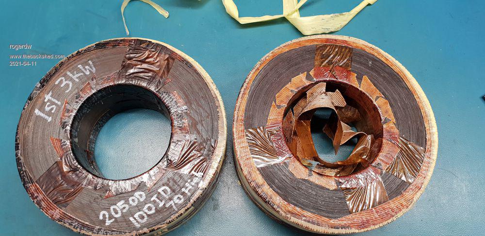
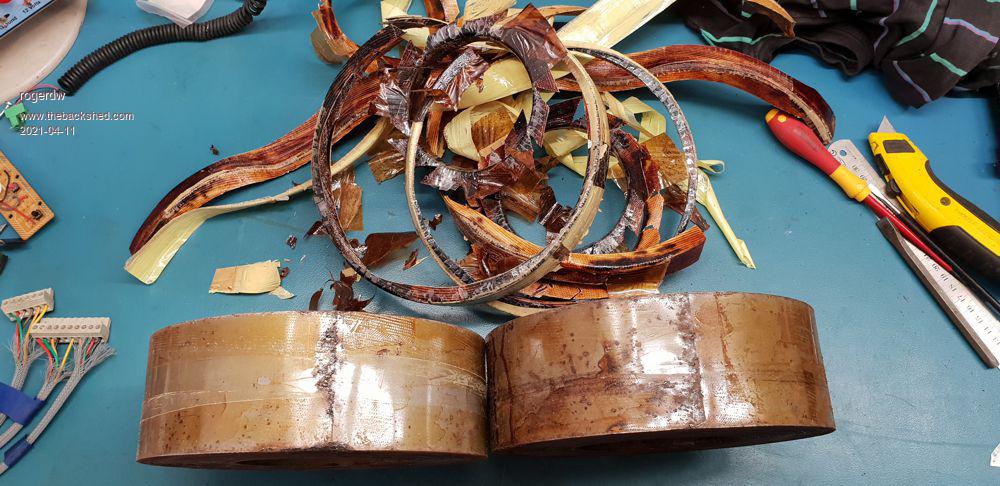
In the meantime, some photos ...
First is of the two 3kW cores ... and then of all the fibreglass binding material they used to insulate the corners etc.
The cores are really rough and both look like they were stored out in the weather before they were originally wound. Quite rusty and even bumps and scrapes on the edges which should have been dealt with before winding.
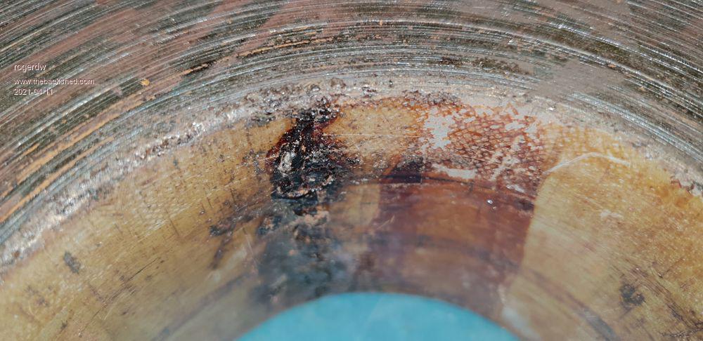
This is not very clear but it is of the welding of the inner part of the core. It actually feels worse than it looks ... and it looks bad enough. It's like someone dropped the handpiece in there and the thing arced and sparked around burning and melting everywhere. It's a mess.
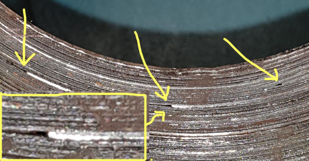
This shot shows that the core is not continuous!!! There are dozens of joins in the whole thing. Here you can see three ... but there are lots more everywhere.
I recall seeing a youtube video of someone winding a core on a hand operated device and adding short lengths of core material all willy nilly ... somewhere in SE Asia. I think he was the guy who made these.
I'm keen to see how the other brand of transformer core is put together but haven't stripped the final layer of mylar off them yet.
Cheers, Roger
Warpspeed Guru Joined: 09/08/2007 Location: AustraliaPosts: 4406
Posted: 09:46pm 11 Apr 2021
Copy link to clipboard
Print this post
Roger, You might care to go to the trouble of measuring the idling power loss of each of those cores before you go any further.
First wrap a decent number of turns of any old wire roughly around the bare core.
From whatever number of turns you finally end up with, use the on line flux calculator to find an applied rms voltage to reach one Tesla with that number of turns, and that core cross sectional area. It might work out to 0.73 volts per turn or something (???) for just one core. That is just an imaginary number I guessed.
If there are seventeen turns, 17 x 0.73 = 12.41 volts for example = one Tesla
Find a way to get 12.41 volts to energise the winding with, maybe a variac, or another transformer with some appropriate resistors, light bulbs. Whatever....
Measure the current in your toroidal test winding at 12.41 volts. Around 10 Va to 15Va for each core would be a reasonable expectation, probably a bit less than one amp in this example.
Idling power is a very good indication of the overall quality of the core. The grade of steel, any internal air voids, or lumps of weld will all tend to degrade the idling efficiency.
That may be excellent top quality steel you have there, but some Chinese guy has probably bought a lot of odd offcuts fairly cheaply as scrap, which all ends up looking a lot worse than it actually is. So you may be in luck. But its probably worth knowing what you have before putting a LOT of time and effort into doing the winding.
The big commercial transformer manufacturers buy massive bulk rolls of steel strip and copper wire, and when getting near the end of a roll, will not attempt to load their machine if there is insufficient to wind one last core without a join. So odd lengths get sold cheap for scrap price. Its just not worth the time and trouble to mess about with joins on their big fully automated machine.Cheers, ĀTony.
rogerdw Guru Joined: 22/10/2019 Location: AustraliaPosts: 904
Posted: 03:55am 12 Apr 2021
Copy link to clipboard
Print this post
Yes, that's starting to look like a good idea. I'll do that.
I have two of each type of 3kW cores so I'll measure one of each and compare them.
Haha ... and it might be the total opposite too!
And probably not worth messing about with joins on a one off coil either ... though I was looking forward to it.
Not sure what it is really ... I could have just bought a couple of brand new larger cores from AEM and sandwiched those ... then I'd know they've been wound properly, annealed and demagnetised ...
... there's just something appealing about building something from junk.
I'll do these tests and then make a decision.
Thanks so much for your advice Tony.Cheers, Roger
Haxby Guru Joined: 07/07/2008 Location: AustraliaPosts: 423
Posted: 05:26am 12 Apr 2021
Copy link to clipboard
Print this post
I bet they switched to the Japanese supplier due to quality issues like this.
Correct me if I'm wrong Tony, but you can do the core test even before unwinding the transformer. I'm keenly interested to see the results!
Warpspeed Guru Joined: 09/08/2007 Location: AustraliaPosts: 4406
Posted: 06:21am 12 Apr 2021
Copy link to clipboard
Print this post
Yes indeed Phil.
You just need to energise the core with a few turns to reach the desired flux density you wish to test at, and the Va required will be the same regardless of the number of turns on the final windings.
Only difficulty is that without first stripping the transformer, there is no real way to measure the core cross sectional area, and that area is the basis of all the design equations regarding the core.
Strictly speaking, core "loss" is only the resistive in phase component of the current which generates heat directly into the core material through hysteresis and eddy current effects. There is also an inductive component (Xl) which generates an out of phase current. Higher inductance reduces that part of the idling current. Better steel has a higher permiability than junk steel, and more inductance per turn as a result.
Its more common to lump the whole lot together as idling Va's, its much easier to measure anyway. So the lower the idling power the more power efficient an inverter will be at low loading.Cheers, ĀTony.
rogerdw Guru Joined: 22/10/2019 Location: AustraliaPosts: 904
Posted: 07:01am 12 Apr 2021
Copy link to clipboard
Print this post
Oaky, I've done the test.
Wound both with 20 turns.
#1Tx is the rough looking Hefei ECU-Tamura
CSArea of 37.1 sq/cm
16.47V RMS gives a result of 1 Tesla on the calculator.
.8235V/Turn
Fed winding with 16.47V RMS and showed reading of .47A
Am I correct in saying that VA = 7.74 ?
#2Tx is the much better looking Eaglerise Electric toroid
CSArea of 35 sq/cm
15.54V RMS gives a result of 1 Tesla on the calculator.
.777V/Turn
Fed winding with 15.54V RMS and showed reading of .36A
VA = 5.59Cheers, Roger
Warpspeed Guru Joined: 09/08/2007 Location: AustraliaPosts: 4406
Posted: 07:20am 12 Apr 2021
Copy link to clipboard
Print this post
That is an excellent result Roger.
Full speed ahead on the rewind....Cheers, ĀTony.
Page 8 of 10
Print this page
The Back Shed's forum code is written, and hosted, in Australia.


 .
.