
|
|
Forum Index : Electronics : Time for a new Warpinverter build
| Author | Message | ||||
| rogerdw Guru Joined: 22/10/2019 Location: AustraliaPosts: 904 |
Ahh umm ... ok.  I guess I was expecting bad news. So you feel it's ok to use some metal from one to build up the other ... or were you just referring to using them as they are? Cheers, Roger |
||||
| Warpspeed Guru Joined: 09/08/2007 Location: AustraliaPosts: 4406 |
You can do the hole expansion trick. I think you can be certain its good steel, not made from resurrected beer cans, or old crushed Holden bodies. But be aware that what you remove from the inside, will have to span a much larger circumference going around the outside. So you lose cross sectional area using the same total mass of steel. But on the other hand, you have a much larger hole into which more turns of larger wire will much more readily fit. So its all a bit complicated. Only way to know is to go through the whole design exercise and work out if the numbers become more (or less) favorable after enlarging the hole. Many ways to skin a cat... I think its probably a good idea, based on the collective experience of many people here on the Forum that are seasoned toroid winding veterans. Edited 2021-04-12 18:08 by Warpspeed Cheers, �Tony. |
||||
| Murphy's friend Guru Joined: 04/10/2019 Location: AustraliaPosts: 671 |
Roger, to give you a ball park figure of how much idling power a finished inverter, using the 3KW aerosharp core re wound, uses: I have just completed re doing the complete electronics for this inverter, it now uses Poida's nano with opto isolated totem pole drivers as per wiseguy's design. The total idle power, including core magnetising current and all the electronics, is 17W at 55V battery voltage. Funnily enough, the original idling power with the EG8010/ IR2110/ totem pole arrangement as per madness design, but with identical transformer as above, took 29W all up to run. So, something to consider down the track if you are concerned about idle power. I'm re doing my warpverter boards to use totem pole drivers, they seem to be much better in handling paralleled mosfets than straight off the FOD3812 drivers as per warps schematic. |
||||
Haxby Guru Joined: 07/07/2008 Location: AustraliaPosts: 423 |
Hold on, let me get this straight. Two 3kw transformers with the same voltages, power ratings, etc, both out of Aero-sharp inverters but from two different transformer manufacturers. The Hefei Ecu-Tamura brand: -looks neat and tidy on the outside -is a little smaller physically - windings are more neatly wound But - the core is made from rusty offcuts. Whereas the Eaglerise brand: - looks more messy on the outside - is a little bigger - windings are pretty messy - internal core better quality with lower measured core losses. Is that right? |
||||
| Warpspeed Guru Joined: 09/08/2007 Location: AustraliaPosts: 4406 |
Its amazing how Forum members have continually raised the performance level of inverter design and efficiency over the years. Back in the early days of the Oz inverter, fifty to eighty watts of idling power at 48 volts for this class of inverter was the accepted norm. And Oz well deserves his place in history for achieving what he achieved. Anything less than twenty watts is truly exceptional, and sets a new standard. Well done guys !! The commercial inverter guys can eat our dust, we are way ahead. Cheers, �Tony. |
||||
| rogerdw Guru Joined: 22/10/2019 Location: AustraliaPosts: 904 |
Nah Phil, somehow you've mixed that up. This is the correct summary ... The Hefei Ecu-Tamura brand: - looks more messy on the outside - is a little bigger - windings are pretty messy And - the core is made from rusty offcuts. Whereas the Eaglerise brand: -looks neat and tidy on the outside -is a little smaller physically - windings are more neatly wound - internal core better quality with lower measured core losses. Note: I haven't removed the mylar from the neat looking Eaglerise toroids yet to see if their cores are better or worse, though certainly don't expect them to be worse. Cheers, Roger |
||||
| rogerdw Guru Joined: 22/10/2019 Location: AustraliaPosts: 904 |
Wow, certainly very impressive and glad to hear you've made such progress. Just so I'm clear here ... this is with an Ozinverter? That's almost half, amazing. So you're putting that down to Poida's nano and opto isolated totem pole drivers as per wiseguy's design? I am too far off finishing yet to be too concerned about idling current ... I just hope I can get it to run, let alone idle.  I don't really understand the principle, but I appreciate Tony's guidance in planning the toroid build to operate at a much lower flux density than general commercial ones. I'm assuming that's where the first big level of idling power is reduced. Cheers, Roger |
||||
| Haxby Guru Joined: 07/07/2008 Location: AustraliaPosts: 423 |
Ok, so one brand is better in every way, and the other brand is worse in every way..... Good! Very good! But I think you still inadvertently swapped the brand names around. The Hefei Ecu-Tamura transformers I have here are smaller and neater than the Eaglerise. |
||||
| rogerdw Guru Joined: 22/10/2019 Location: AustraliaPosts: 904 |
Yes, you are right Phil and I was wrong. I've gone round and round for the last couple hours trying to work out how I mixed it up ... and my notes are pretty clear, yet I still messed it up. My apologies. Hope it doesn't mess anyone else up. Cheers, Roger |
||||
| Murphy's friend Guru Joined: 04/10/2019 Location: AustraliaPosts: 671 |
I should tell you here that I followed the "ozinverter" story for about 12 years by now, the first version was what everybody did back then, buying the power & control PCB from Powerjack and do the rest at home to make an inverter. Still have those bits somewhere  . .When Oztules started to make his own PCB and everybody, including myself, had to try that too  I diverted early from his idea of having a humongous size 2oz power board and a separate control board. Nowadays known as the madboards. I diverted early from his idea of having a humongous size 2oz power board and a separate control board. Nowadays known as the madboards.It it much easier to make the power board as two separate half bridges which I have improved ever since. Mk 4 design or so I think its by now. So much so that I get away with 1oz boards, even for the 6KW inverter. So, yes, that idling power is with a single transformer inverter though I don't call it "ozinverter" as it only resembles his pioneering work in principle but no more. When my warpverter was working I recall the combined idling power was <30W for the 4 transformers & electronics. I'll update that when the new version is up and running. |
||||
| rogerdw Guru Joined: 22/10/2019 Location: AustraliaPosts: 904 |
Thanks for that background information, it helps in understanding your journey. I only found this forum and all you guys because I wanted to understand why a normal grid tie inverter couldn't be made to run as a stand alone device. It really got my attention when I read how many of you were building your own inverters and I started to get enthusiastic. I wasn't all that keen on building a Warpinverter to start with because of it needing four transformers and not just one ... but as I got to understand it a little better I figured why not give it a go ... especially with all the expertise and information available here. If mine has a combined idling power of <30W I'll be very happy too. Cheers, Roger |
||||
| Haxby Guru Joined: 07/07/2008 Location: AustraliaPosts: 423 |
No problems at all! I was just making sure I knew which transformers to look out for and which ones to prefer. Since I don't unwind them, I have no way of checking what the cores look like. |
||||
| BenandAmber Guru Joined: 16/02/2019 Location: United StatesPosts: 961 |
The tranny core I wound from a few smaller cores has a higher than normal idle current when I plug the 120 volt winding in a 120 volt wall outlet I can't remember what the idle current was but from a very poor can't be trusted memory I think it was 0.1 something normal or stacked cores after the wind more turns until it makes little difference method will be 0.0 something I have never wound a low side winding to try it out that I can remember I was very careful to do the best job possible on the core winding and the 120 volt winding I was thinking that maybe from unwinding and rewinding the core metal was cold worked making it a better conductor less resistance requiring a new heat treatment of the core This is the only thing I can think of to make the higher idle current take this with a grain of salt My hero on all things Transformer that I owe all of my understanding about trannys to and could never give thanks to him enough in many life times has already been giving his priceless advice on this post so he will likely chimed in and correct me where I'm wrong He would know if my thoughts are right or wrong about the higher idle current I am sorry I just read your post and my input is so late I hope you will also forgive me for the very long post I have removed metal from the center of many Transformers without adding any to out side it always works out great with very low idle current The same goes for stacking Transformers I am convinced that the very best Transformers are taller than they are wide and the worst with higher idle are alot wider but short I have now had many examples of both shapes and every time so far the really wide short ones have high idle really tall ones a single stack or three or four core stacked on top of each other have the best Idol of all shapes I am not saying this is a fact but it is a fact with every Transformer I have wound and that's a lot of coincidences I dont claim to have even a very small fraction of knowledge on this subject as the many greats on this form but I have now wound Transformers for people all over the usa along with other than personal people My personal OPINION from the knowledge I have gained from my tranny hero that has no clue of the impact he has had on my life his wisdom not of my own I or anyone else can make a Transformer that is as good as or better than any other Again I humbly say this not my wisdom but heros and it is a simple process that a slow person like myself can easily do I hope everyone will take me the right way I am trying to give back freely in the spirit it and many other things was freely given to me If you follow this simple method you will get a completely silent lowest possible idle current tranny I still don't know how to figure with math how many turns goes on a core A core I guess can do 4000 watts or over I tightly wind 100 turns paying close attention to make sure the wire has no gap in between it and core I give the hole special attention The core has at least 3 layers of stretching tight tranny tape around it before any wire is wound if the tape is the thinner skinny tape at least 4 I leave the wire long on this first 100 turns I use the light bulb switch trick and check idle current then add 8 or 10 turns check again and repeat until the idle current doesn't go down much for the extra turns then I unwind one turn to see if current is the same or raised if same unwind one more repeat until it goes up and add the one turn back that made it go up With cores of over 50 pounds 100 turn could be to many just adjust up or down for lowest idle After the first 120 volt winding I wind the second 120 volt winding and when I think I am close I do light bulb switch trick again this time fist measuring voltage coming out of outlet at that moment mine can vary over 9 volts from minute to minute then I measure the voltage on the 2nd 120 volt winding to see if I wound too many turns or need to wind a few more I make these two windings the exact same voltage testing them four or five times very quickly because of the possible change in voltage coming from plug This will have to be done in pairs of two until you reach the required amperage the Transformer will need to reach the desired wattage you must check and double check that all single winding have the exact not one volt of voltage this is critical sure I check and double check and double-check with every winding all of them when plugged in with the light bulb trick I try to make each winding take up a single layer on the Transformer and I add at least two layers I've overlapped tightly stretched tranny tape and between every winding if a hole winding does not fit on a single layer before adding the needed extra turns to make up one of the 120 volt windings it gets two layers of overlapped tightly-wound Transformer tape then before the start of the next winding the extra turns gets to tightly wrapped overlapped layers of tranny tape I never quite understood how to do the math on how much amperage a squared wire wood handle so whatever wire I'm using for example 12 gauge on the awg chart is 20 amp 14 gauge is 15 amps one size smaller wire and I use this one size smaller amperage rating for the absolute highest possible amperage to go through that single wanding After I put all the wire I can possibly get on even if the wire can handle more amperage than the wattage the Transformer is going to be I still add as much copper on both high and low sides as possible I almost never have much room left in the hole my requirements is I have to have enough space to get the bolt through Now how much wattage will a certain size core handle a very rough guesstimate is around 10 lb of core 4 1000 watts this estimate goes down as wattage goes up for example a complete Transformer wire and all that weighs 50 to 55 pounds is good for 5 to 6 thousand watts so the higher up you go in wattage of a transformer the less pounds of core you will need for that wattage but the higher up in wattage you go the more copper you will need for that wattage even though the ratio of Transformer core weight goes down with wattage the copper ratio goes up with wattage But there is more to it than this I have bought a 3000 watt and others used Transformer that was a isolation Transformer I'm guessing where the input voltage primary and secondary was very close to the same voltages and still had enough whole left without unwinding neither primary or secondary winding to add a new low side winding I still do the light bulb switch trick and add extra windings to make both the primary and secondary have the exact same voltages and have the lowest possible idle current But I have found out the magnetic link between both sides of the tranny is there when almost doubling the wattage of the tranny by using the original primary and secondary as one your new high side and adding a new low side There is a problem though how long can you run this now almost double the original wattage before it heats up Well that depends on how well your cooling is lots of fans or in oil will stretch the amount of time you can run this now higher wattage One more thing most or all high wattage apliances used in our homes don't run constantly the kick on and off so you may not even need extra cooling because it doesn't have enough time to heat up before the apliance kicks off giving it time to dissipate heat before the next cycle There are quite a few advantages of doing it this way if you can reach a good balance so high speed fans almost never kick on mabe a few rare occasions a couple times a year this can be and is currently a good balance between price and cost for a lot of people Along with winding from scratch or taking advantage of a used Transformer with the same voltage for the primary and secondary you still have to figure out what they call the dot of a transformer if you add two windings up backwards the voltage will cancel itself out like a short when doing this you will want the light bulb to always be in circuit so leave your switch off so the power has to go through your light bulb and don't get bypassed by your switch When from scratch winding or used tranny you parallel wires together to have two separate but equal 120-volt windings After confirming that you have all of them paralleled up in two separate but equal windings with the right polarity you will have to hook one end of the two sets of paralleled winding up to each other to make your center tap just try any two use light bulb on one 120 volt winding from center tap to ether of the legs you will get 120 volt even if you have the wrong side of one of the two 120 volt windings hooked together for your center tap so you must check for 240 on the two not center tap wires if you have 240 your polarity is right and you keep the two wires you have hooked up for center tap if voltage is zero switch only one side of the hundred and twenty volt winding to Center tap then check again and you will have 240 volts The center tap 240 volt test dose not short the wire if not going through light bulbs if you chose to go through light bulb any way two wires that are not center taped will be double the voltage of from center tap to one 120 volt leg if not dubbed then switch one wire and it should be Here in USA we use 240 with a center tap so we get two legs of 120 or 240 across the two l20 legs Cook stove hot water heater furnace central air are the most common 240 volt loads and our regular Outlets all over the house musers 120 volts Please forgive me for the long text I really hope this clears things up for some of the new people here I know this is nothing that a lot of you guys already haven't known for years but this is things that were hard learned for me even though some of it people tried to tell me and explain it to me over and over Thanks for your time I hope I didn't hijack your post be warned i am good parrot but Dumber than a box of rocks |
||||
| Haxby Guru Joined: 07/07/2008 Location: AustraliaPosts: 423 |
I also don't want to hijack the thread but as I read BenAndAmber's post it got me thinking about whether you would have to wind 8 transformers for a warpverter design in the USA for split phase. Then you mention using a store-bought 1:1 toroidal isolation transformer and adding the low voltage windings through what's left of the existing hole, which gave me an idea. If you were to use one of these transformers in a warpverter design, you would get a split phase output quite easily and you wouldn't have to wind 8 transformers for a split phase output. You would use 4 transformers but wind them as follows: 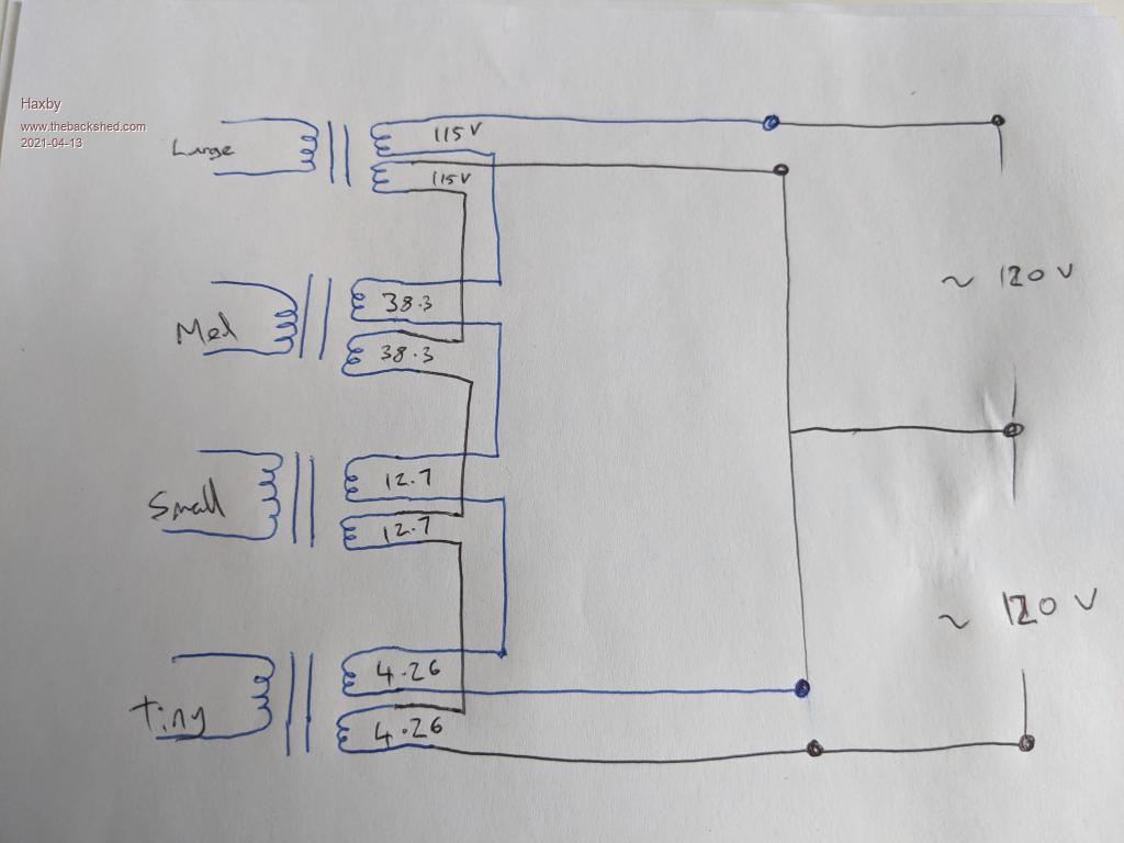 |
||||
| Warpspeed Guru Joined: 09/08/2007 Location: AustraliaPosts: 4406 |
Yes Phil, that is the ideal way to do split phase for an American Warpverter. Two quite independent 120v outputs that could be connected either in parallel or series as required. Edited 2021-04-13 15:17 by Warpspeed Cheers, �Tony. |
||||
| Haxby Guru Joined: 07/07/2008 Location: AustraliaPosts: 423 |
Would it really be ok connected in parallel? |
||||
| Haxby Guru Joined: 07/07/2008 Location: AustraliaPosts: 423 |
I guess just have to be very careful with matching the windings |
||||
| Warpspeed Guru Joined: 09/08/2007 Location: AustraliaPosts: 4406 |
Yes indeed !! Very important that the turns are exactly the same on each of the secondary pairs. But that should be easy to verify during winding. Its no worse than running multiple layers in parallel which is what people are doing now anyway. Cheers, �Tony. |
||||
| rogerdw Guru Joined: 22/10/2019 Location: AustraliaPosts: 904 |
Yeah that's breath holding time when you power up one and check each of the others. Big sigh of relief when they all measure the same. Cheers, Roger |
||||
| rogerdw Guru Joined: 22/10/2019 Location: AustraliaPosts: 904 |
I found a video of a guy winding a toroid core from ribbon steel ... I wonder if he's the one who made them for Aerosharp before they changed suppliers. https://www.youtube.com/watch?v=aTBWx5bS8Ns Cheers, Roger |
||||
| The Back Shed's forum code is written, and hosted, in Australia. | © JAQ Software 2025 |
