
|
|
Forum Index : Microcontroller and PC projects : ArmmiteF4 firmware V5.07.00b1 - major upgrade
| Author | Message | ||||
| matherp Guru Joined: 11/12/2012 Location: United KingdomPosts: 10273 |
Can't compete  here is my dev board with the OTM8009A_16 connected. There is something odd about my display. Although it has the XPT2046 touch chip installed the screen itself doesn't have the resistive touch overlay. You can see that the normal 4-pin ribbon from the screen is missing. You should try and avoid this version if purchasing one of these if you need touch 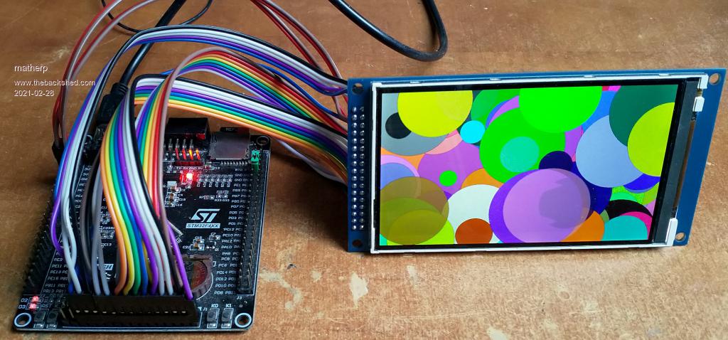 Edited 2021-02-28 03:15 by matherp |
||||
| RonnS Senior Member Joined: 16/07/2015 Location: GermanyPosts: 121 |
Hi Peter ; I have no access to the SD card with mminfo$(SDCARD) I only get "not present" what can be the reason for this? two cards tested thx Ron |
||||
OA47 Guru Joined: 11/04/2012 Location: AustraliaPosts: 982 |
I am not sure if this relates to RonnS problem but I have narrowed down a similar problem I have been chasing for some months. It seems if I use PC13 (Pin 7) for DIN it causes unreliability with the SDCARD. If I disconnect the connection from Pin 7 to the opto-coupler including its 3v3 supply and 10K pullup resistor the SDcard works ok. This may be something that MatherP could look into when it is convenient and he has the time. Here are some snippets of code that I have been using: Dim ValvePin(16) ' PINS USED FOR MONITORING THE CONTROLLER 24V AC OUTPUTS (1-16) VIA OPTO-COUPLERS ' PE2,PE3,PE4,PE5,PE6,PC13,PC0,PC1,PC2,PC3,PA0,PA1,PA2,PA3,PC4,PB0 Data 1, 2, 3 , 4 , 5 , 7, 15 ,16, 17, 18, 23, 24, 25, 26, 33, 35 For I = 1 To NumPorts Read ValvePin(I) SetPin ValvePin(I), DIN, Pulldown 'Valve sense pin numbers Next I If I let NumPorts=5 or swap out pin 7 with another pin, SD works OK. I have used the above sequence of I/O pins as I have made PCBs that connect to those pins. OA47 Edited 2021-02-28 13:05 by OA47 |
||||
| matherp Guru Joined: 11/12/2012 Location: United KingdomPosts: 10273 |
PC13 is on the same H/W port as the SDcard connection internal to the chip (next to the SD clock signal). I would suspect some sort of internal cross-talk in the chip. Nothing I can do about that, you could try making sure the input to PC13 is high impedance with a series resistor. Otherwise you will just have to avoid that pin. Faulty card , dry joint, poor power supply. Are you using the latest firmware? |
||||
| OA47 Guru Joined: 11/04/2012 Location: AustraliaPosts: 982 |
Thank you Peter for providing that information. I will make other arrangements to get the system up and reliable. OA47 PS with all the magic that you have produced with these chips I could only wonder if you were able to modify things in the die as well.  |
||||
| RonnS Senior Member Joined: 16/07/2015 Location: GermanyPosts: 121 |
tried 2 cards (32GB), I use the latest firmware, in an earlier version it worked with the same hardware.... will check it with an earlier version if I have time |
||||
| RonnS Senior Member Joined: 16/07/2015 Location: GermanyPosts: 121 |
im back..; it works with an 8GB SD Card... 32GB seems to much thx Ron |
||||
| Volhout Guru Joined: 05/03/2018 Location: NetherlandsPosts: 5072 |
I got the same surprize on the most recent ILI9341 ISP board I received. No touch screen, but the controller is soldered. They just didn't put the resistive foil on the glass. Edited 2021-03-01 03:15 by Volhout PicomiteVGA PETSCII ROBOTS |
||||
| lizby Guru Joined: 17/05/2016 Location: United StatesPosts: 3367 |
That explains a mystery. I've been getting "No SD card" (or similar). I had PC13 set as RESET for the ESP-01 (which does reset, but the ESP-01 hasn't worked off my breadboard). Unplugging PC13 from the F4 board has given me back the SD card. Ok, I'm going to declare PC13 out of bounds for my use--don't want to be scratching my head about unexplained behavior. ~ Edited 2021-03-01 03:42 by lizby PicoMite, Armmite F4, SensorKits, MMBasic Hardware, Games, etc. on fruitoftheshed |
||||
| Volhout Guru Joined: 05/03/2018 Location: NetherlandsPosts: 5072 |
Please note that PC13 is a special pin, together with PC14 and PC15 it has is't own low power domain (32kHz clock). It has limitted drive capabilities. 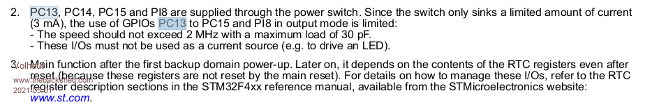 Maybe we should mark this in the manual. That PC13 should be avoided if possible. Note that in power down mode, PC13 could even supply voltage, since it is in the RTC domain, and is not reset. So put the line high, and you should have a 3V battery output. Edited 2021-03-01 04:23 by Volhout PicomiteVGA PETSCII ROBOTS |
||||
| lizby Guru Joined: 17/05/2016 Location: United StatesPosts: 3367 |
I had the PC13 pin connected to RESET on the ESP-01 through a 1.2K resistor (and RESET should not be power-draining anyway). Without this clue I would never have guessed that it could have caused my SD card problem. PicoMite, Armmite F4, SensorKits, MMBasic Hardware, Games, etc. on fruitoftheshed |
||||
| matherp Guru Joined: 11/12/2012 Location: United KingdomPosts: 10273 |
Attached is b5 ArmmiteF407.zip This implements pin(iref), pin(sref), pin(temp) and blocks pin(0). Thought these were in a previous release but apparently not based on comments above It also fixes CPU SLEEP [n] when using a USB console but to make this work you need to remove R21  otherwise this pullup resistor keeps the USB link active so the processor can't sleep. Related to this I've made changes to the USB initialisation so the firmware works much better on the mini STM32F407 board which doesn't have the pullup resistor  Edited 2021-03-01 05:07 by matherp |
||||
| Volhout Guru Joined: 05/03/2018 Location: NetherlandsPosts: 5072 |
Dear Peter, I did some work for disco4now who is creating the F4 manual. In this investigation I ran into something strange. setpin PE3,fin,10000 do print pin(PE3) pause 10000 loop allows measuring the input frequency. This works well up to 1.8MHz. When applying 2MHz at the input pin PE3 the system becomes unresponsive. No serial output anymore. Even ctrl-C can't stop the execution anymore. It feels like the CPU is so busy counting at high level, that lower tasks as serial do or the timer do not work anymore. Is this something that can be fixed, or is this inherent to the way frequencies are measured. There is plenty of margin from the 300kHz that is specified, so this should normally not happen. On the other hand, you measure a frequency because you don't know it...... Regards, Volhout PicomiteVGA PETSCII ROBOTS |
||||
| Volhout Guru Joined: 05/03/2018 Location: NetherlandsPosts: 5072 |
Hi Peter, With version b5, the list commands and list functions is nicely aligned (I did not test previous version where you fixed it, but I do confirm now). About iref and sref: Do a=Pin(sref) b=Pin(iref) v33=3.3*a/b Print a,b,v33 Pause 1000 Loop 1.207179487 1.203956044 3.308835341 1.207179487 1.208791209 3.2956 1.207179487 1.20959707 3.293404397 1.207179487 1.207985348 3.297798532 1.207179487 1.207985348 3.297798532 1.207179487 1.20959707 3.293404397 1.207179487 1.215238095 3.278116711 1.207179487 1.20959707 3.293404397 1.207179487 1.207985348 3.297798532 1.207179487 1.207179487 3.3 1.207179487 1.212014652 3.286835106 So it works. It even shows some variation. So they are not static. I have my doubt about the actual values, but since I typically calibrate in my own software this is not a big issue for me at all. Volhout edit: I did a new run, and measured with my Fluke multimeter Th actual board voltage did not vary (not even 1mV), so the jitter in above results is from the ADC sampling. The jitter measured is +/- 0.5%. This is quite a lot for a 12bit ADC. The steps in the 3.3V measurement are around 10 bit. But the value measured is 1.2V which is 1/3 of the ADC range, so you are actually using 12bit mode. Maybe the variation is due to ripple on the 3.3V. which would be 30mVpp then. Quite a lot for a linear regulator. Edited 2021-03-01 06:33 by Volhout PicomiteVGA PETSCII ROBOTS |
||||
| Volhout Guru Joined: 05/03/2018 Location: NetherlandsPosts: 5072 |
EDIT: I was wondering why the iref/sref mechanism exists, but I finally got it. This processor can also be used in battery powered applications, and then the VCC can vary from 3.6V....1.8V. In that case it is absolutely nice to know what your ADC range roughly is, and not only to measure the battery voltage... Hi Peter, This feedback on the iref/sref functionality is not meant to request a change, but my curiousity if it is usable, and practical. To check the variations on the sref/iref calibration I simply did very many (10000). h=0 l=4 For i=1 To 10000 a=Pin(sref) b=Pin(iref) v33=3.3*a/b h=Max(v33,h) l=Min(v33,l) Next i Print h,100*((h/3.3)-1);"%",l,100*((l/3.3)-1);"%" > The result is that the values from this calibration varies between > run 3.324411567 0.7397444519% 3.269444444 -0.9259259259% > Between +0.74% and -0.92%. In essennce this is inherent to the use of a 12bit ADC measuring at 1/3 of it's range (1.2V) so the error at 1.2V tripples for full range, doing 2 measurements, that each are +/- 1 lsb minimal (assume 12 effective bits). So your calibration is already +/- 6 lsb minimal on full range. That degrades the DC accuracy of the 12 bit ADC to 9 bits best case. I think the iref/sref calibration using OPTION VCC is not as accurate as simply measuring the VCC and using that in a simple multiplication or put that value in OPTION VCC Again, no criticism on the software, you may be able to implement some averaging on the sref value, but the iref value (half the error) is already programmed by ST, and looking at the value, it is also from a single ADC conversion. Edited 2021-03-01 23:47 by Volhout PicomiteVGA PETSCII ROBOTS |
||||
TassyJim Guru Joined: 07/08/2011 Location: AustraliaPosts: 6271 |
I think there is a bug in the INPUT$(x,#fn) function MMBasic Version 5.07.00b5 I can't read the last byte of any file. OPTION EXPLICIT OPTION DEFAULT NONE DIM f$ = "FTPserver.ini" DIM a$ DIM INTEGER x ,n OPEN f$ FOR INPUT AS #4 PRINT LOF(#4) SEEK #4,1 a$ = INPUT$(255,#4) PRINT LEN(a$) SEEK #4, LOF(#4) a$ = INPUT$(1,#4) PRINT LEN(a$) CLOSE #4 > RUN 235 234 0 > LOF(#4) and LEN(a$) should be the same. FTPserver.ini is a short text file about 240 bytes long. The problem occurs with files of any length. I tried reading one byte at a time but still no joy. I also noticed that PRINT to a file only adds <LF>. Is there an option to set it to <CRLF>? Jim Edited 2021-03-04 14:18 by TassyJim VK7JH MMedit |
||||
| TassyJim Guru Joined: 07/08/2011 Location: AustraliaPosts: 6271 |
It works correctly if I open the file as RANDOM instead of INPUT Jim VK7JH MMedit |
||||
| matherp Guru Joined: 11/12/2012 Location: United KingdomPosts: 10273 |
Attached is b6 ArmmiteF407.zip Fixes a bug in File handling as identified by Jim above. Also includes getscanline() function for both ILI9341-16 and OTM8009A_16 (thanks Gerry) Edited 2021-03-06 01:01 by matherp |
||||
| TassyJim Guru Joined: 07/08/2011 Location: AustraliaPosts: 6271 |
Thanks Peter, working much better now. Next Comment: CWD$ doesn't return any drive letter. It always starts with ':/' Then if you use the result for CHDIR there is an error because CHDIR doesn't like a path starting with ':' It needs either drive letter or starting with '/' I have coded around it by adding the missing 'A" to the paths. > chdir "/" > print cwd$ :/ > chdir ":/" Error : The logical drive number is inv > chdir "A:/" > print cwd$ :/ Jim VK7JH MMedit |
||||
goc30 Guru Joined: 12/04/2017 Location: FrancePosts: 435 |
Hi Peter with 2 last versions, I have same problem with SDCard, who said all time "Sd Card Not present" I have 2 differents boards (407VET6 and 407VGT6) and same problem with 2 cards I have nothing connected and no lcdpanel. I add an power card to have corrects volts +3.3v and +5v). Maybe just small detail who have no effects: In your old src files, I have seen that in "fileIo.c", you don't initialize Option.SD_CD when it is an F407 chip, and value =0 (=false??) For all other, very good job and thanke |
||||
| The Back Shed's forum code is written, and hosted, in Australia. | © JAQ Software 2025 |
