
|
|
Forum Index : Microcontroller and PC projects : ArmmiteF4 firmware V5.07.00b1 - major upgrade
| Author | Message | ||||
disco4now Guru Joined: 18/12/2014 Location: AustraliaPosts: 1001 |
Thanks Panky, Good to know in flash mode(i.e MMBasic) it needs no jumper at all. They are a bit fiddly when doing frequent firmware updates. I have a 4*2 socket with the right pins bridged that I put on when doing a firmware update,now I can forget about putting that jumper back each time. The new manual will link to your schematic. Regards Gerry PS. just noticed the table showing BOOT 0 and BOOT 1 settings is different in the English version. I think it should be like this. I just proved that you don't need to have a jumper for BOOT 1 at all. It tied to GND which satisfies both the Don't care and 0 settings. So jumper on Boot 0 pin is the only one you need to worry about. Can be missing for MMBasic mode, but needs to be jumpered to 3.3v for loading firmware.  Edited 2021-02-24 14:44 by disco4now Latest F4 Latest H7 FotS |
||||
| panky Guru Joined: 02/10/2012 Location: AustraliaPosts: 1114 |
Cheers Gerry, Corrected schematic STM32F407VET6_schematic-english-2.pdf I also have it in .ODG (Libre Office Draw) format so it can be edited if required - let me know if you want that to embed in your manual. Regards, Doug. ... almost all of the Maximites, the MicromMites, the MM Extremes, the ArmMites, the PicoMite and loving it! |
||||
CircuitGizmos Guru Joined: 08/09/2011 Location: United StatesPosts: 1427 |
Thanks! Micromites and Maximites! - Beginning Maximite |
||||
| CircuitGizmos Guru Joined: 08/09/2011 Location: United StatesPosts: 1427 |
Even better! Thanks! Edited 2021-02-25 09:49 by Gizmo Micromites and Maximites! - Beginning Maximite |
||||
| Zonker Guru Joined: 18/08/2012 Location: United StatesPosts: 767 |
Been getting updates and wondering if there is a PDF manual on this version... I am trying to collect all the data on this excellent project...  |
||||
| lizby Guru Joined: 17/05/2016 Location: United StatesPosts: 3367 |
See the first post, line 4. It's coming. PicoMite, Armmite F4, SensorKits, MMBasic Hardware, Games, etc. on fruitoftheshed |
||||
| Zonker Guru Joined: 18/08/2012 Location: United StatesPosts: 767 |
Wow.. Guess I missed it...  I for sure want to Matherp & Gerry Alardice and everyone for the awesome work on this project... Many fine things can be created with this MCU...  |
||||
| disco4now Guru Joined: 18/12/2014 Location: AustraliaPosts: 1001 |
Just a link the the draft of the Armmite F4 User Manual. Armmite F4 User Manual Latest F4 Latest H7 FotS |
||||
| matherp Guru Joined: 11/12/2012 Location: United KingdomPosts: 10273 |
Please note that currently the CPU SLEEP [n] command only works when the serial console is enabled and locks up if the console is running over USB. I'll try and fix but currently can't find a solution so this may become a limitation |
||||
| Volhout Guru Joined: 05/03/2018 Location: NetherlandsPosts: 5072 |
wauw disco4now, I am impressed !!! Just what I myself also planned to do. Do you want me to look into some of the red and yellow area's? Volhout edit: appart from the highlighted area's there could be issues with: - ADC part (refers to 480MHz and recording 3 ADC's simultaneous - ENDIF is double in the command list - CAT refers to the INC command ? - on F4 the command LIST FILES is still the older FILES - The PAGE #n command refers to CMM2 - GETSCANLINE refers to CMM2 Edited 2021-02-27 06:03 by Volhout PicomiteVGA PETSCII ROBOTS |
||||
| lizby Guru Joined: 17/05/2016 Location: United StatesPosts: 3367 |
I hooked up one of these amplifiers to the F4 DAC pins (through 4K7 series resistors), ran PLAY WAV "shuffle.wav", and got good sound on my earphones. 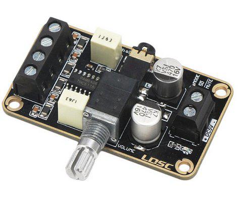 But it would reset the F4 when powered on, and when the volume was powered up more than about a third (which was plenty loud on the earphones). (5V power came from the F4.) Can someone recommend a less power-hungry amplifier (and perhaps one with a smaller footprint). And is there a smallish circuit which could go on a PCB to achieve the necessary amplification? Perhaps like this, twice, with a 5V supply instead of 9V? How would one adjust the volume? 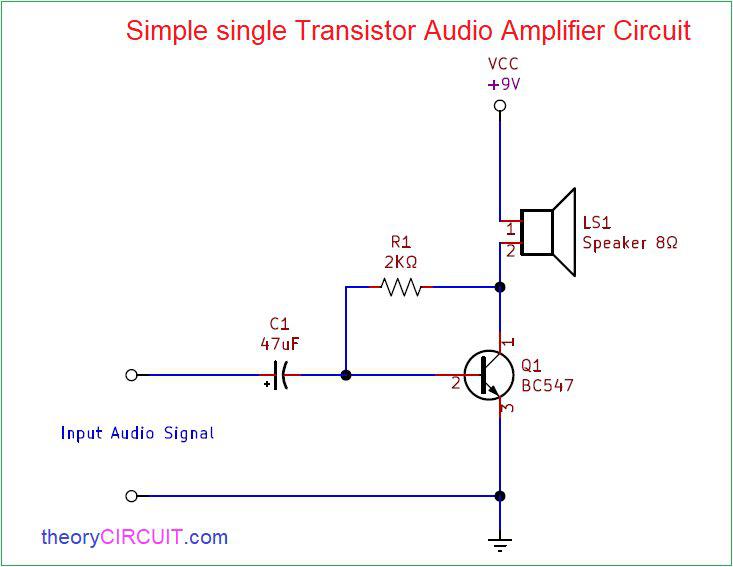 ~ Edited 2021-02-27 10:11 by lizby PicoMite, Armmite F4, SensorKits, MMBasic Hardware, Games, etc. on fruitoftheshed |
||||
| Volhout Guru Joined: 05/03/2018 Location: NetherlandsPosts: 5072 |
Hi Lizby, I used this: headphone out For 32 ohm headphones should be okay. Duplicate with input PA5 if stereo is needed. This is NOT for hifi. Especially noise reduction from the 5V line is little. If you have a backlight PWM at low frequency you can hear it in the speaker. For my tetris game this is not a problem, it gives a nostalgic feeling (try picking up an old game boy). You can improve by changing 22uF to 100uF (better low frequency) and add some 5V filter (i.e. 10 ohm and 100uf). Volume control is in MMBasic Volhout Edited 2021-02-27 17:43 by Volhout PicomiteVGA PETSCII ROBOTS |
||||
| Volhout Guru Joined: 05/03/2018 Location: NetherlandsPosts: 5072 |
@matherp The 5.07b3 firmware has "list commands" and "list functions" but these do not format well on the 80x24 screen of the default terminal. Could be a inheritance from CMM2 that has 100x50 screen. Maybe if you restrict to 4 columns (there are 5 columns now) it looks better. Regards, Volhout PicomiteVGA PETSCII ROBOTS |
||||
| lizby Guru Joined: 17/05/2016 Location: United StatesPosts: 3367 |
Ah, thank you. From the manual: Utility Commands: PLAY PAUSE PLAY RESUME PLAY STOP PLAY VOLUME L, R PicoMite, Armmite F4, SensorKits, MMBasic Hardware, Games, etc. on fruitoftheshed |
||||
| lizby Guru Joined: 17/05/2016 Location: United StatesPosts: 3367 |
And also, for the sake of those of us with OCD, could you strip off the trailing "(" in the functions list? PicoMite, Armmite F4, SensorKits, MMBasic Hardware, Games, etc. on fruitoftheshed |
||||
| matherp Guru Joined: 11/12/2012 Location: United KingdomPosts: 10273 |
No| Same on all versions and indicates the difference between functions with parameter and those not Thought I'd fixed that but missed something - try now ArmmiteF407.zip |
||||
| lizby Guru Joined: 17/05/2016 Location: United StatesPosts: 3367 |
In preparation for trying the SPI ILI9481 480x320 LCD when it arrives (slow boat shipping), I wired up an SPI ILI9341 320x240. > option lcdpanel disable > OPTION LCDPANEL ILI9341, L, 87, 97, 33 > GUI TEST LCDPANEL And it works--lots of disks, reasonably fast to my mind. But then to test LCD CONSOLE; > OPTION LCDPANEL CONSOLE Error : Display required Am I missing something? Is touch calibration required (I didn't wire that)? ~ Edited 2021-02-28 01:34 by lizby PicoMite, Armmite F4, SensorKits, MMBasic Hardware, Games, etc. on fruitoftheshed |
||||
| matherp Guru Joined: 11/12/2012 Location: United KingdomPosts: 10273 |
Console is only supported on parallel I/F displays otherwise scroll too slow Edited 2021-02-28 01:33 by matherp |
||||
| lizby Guru Joined: 17/05/2016 Location: United StatesPosts: 3367 |
Ok, then awaiting OTM8009A_16 3.97" IPS 800*480 display--probably even longer to arrive. PicoMite, Armmite F4, SensorKits, MMBasic Hardware, Games, etc. on fruitoftheshed |
||||
| lizby Guru Joined: 17/05/2016 Location: United StatesPosts: 3367 |
Here's the Christmas tree I'm working on pending arrival of the backpack PCB for the F4: 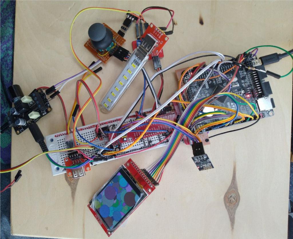 The red part plugged in at the right of the breadboard is a breakout for a 40-pin cable from the pi-type header (as on the CMM2). I've checked the pins and functions for many components. I will later be designing an "Experimenter's" breakout board for the 40-pin header that will allow many of the "37-sensor" kit parts to be plugged in, as well as servos and other toys. PicoMite, Armmite F4, SensorKits, MMBasic Hardware, Games, etc. on fruitoftheshed |
||||
| The Back Shed's forum code is written, and hosted, in Australia. | © JAQ Software 2025 |
