
|
|
Forum Index : Electronics : Circuit to flash one LED then the other at about a second each.
| Author | Message | ||||
| bob.steel Senior Member Joined: 27/02/2020 Location: AustraliaPosts: 188 |
Starting to think I'm the victim of a close knit leg pulling joke group actually.Ha Ha . Seriously though can anyone suggest some voltage test points I can probe for . I don't understand the operation of the circuits when you say components are doing double duty . I would like to understand that. Ive spent days now trying to get this circuit to work and it won't . Position is it flashes right led briefly then turns the left led on hard turning the right off. As good as I can do . Here it is on a breadboard , lets see if you can find a fault . 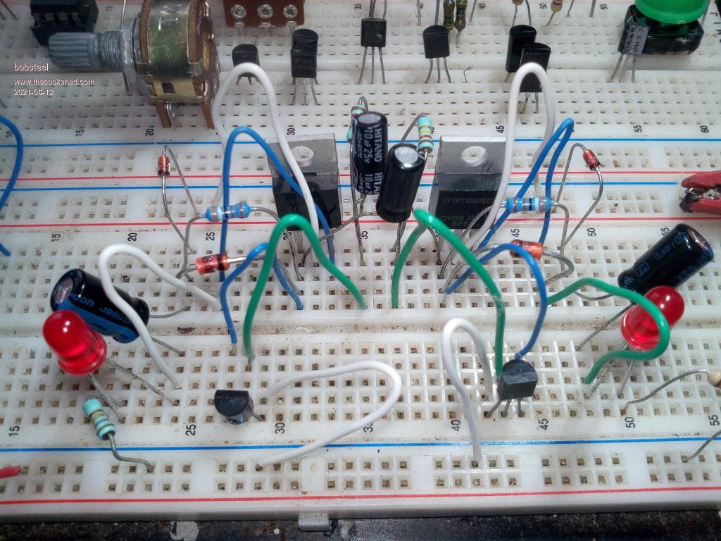 Another one a little later when inet not clogged here. Edited 2021-06-12 16:39 by bob.steel |
||||
| Warpspeed Guru Joined: 09/08/2007 Location: AustraliaPosts: 4406 |
Definitely not ! I have had similar problems with my solar hot water heater circuit. I suggested a circuit, built it, tested it, even had boards made that I supplied fully loaded and tested. But some people have never been able to make it work. I have no idea why that is so, it works fine here. I have no idea what the problem is, but its an uncomfortable situation for both yourself and Mike. Cheers, ĀTony. |
||||
| wiseguy Guru Joined: 21/06/2018 Location: AustraliaPosts: 995 |
That was a good idea to send the picture. What are the small transistors are they the C2655 - it looks like you have wired it as if they were 2N3904's ? If they are C2655's swap the green and blue wires on both small transistors and try again. (ie blue to the centre green to outer). If it gets too hard, maybe Ill go build mine again and take a picture of it. The more than 1 function comment is described a bit better below: The current limit resistors (3K9 on your board) for the FET gates are also the collector resistors for the multivibrator bipolar transistors. The zeners allow the 2 gate capacitors to charge when the transistor connected to its gate is on (they are forward biased ~0.65V) and then hold the gate voltage to the value of the zener voltage when the transistor is off. The 2 x bipolar transistors act as a multivibrator pair and also alternately control the connected FET to be on and off. Edited 2021-06-12 20:05 by wiseguy If at first you dont succeed, I suggest you avoid sky diving.... Cheers Mike |
||||
| bob.steel Senior Member Joined: 27/02/2020 Location: AustraliaPosts: 188 |
No joy there . ive tried it a few ways with a few transistors and a few Mosfets . It doen't work and I often get both led's on at the same time . I'm convinced its not going to work . If you build it again what might help is a few expected voltages on points of the circuit to check against Then if I'm not getting those I can track down my errors. I'm good at this . I built Forrest Mimms version on a breadboard and it worked fine but then I took the voltage over 20v and the mosfets died I think .I'll have to get something sorted soon. |
||||
| wiseguy Guru Joined: 21/06/2018 Location: AustraliaPosts: 995 |
That is taking this on with totally the wrong mindset. It DOES work ! See here One of the first things I learned in electronics is hmmm its not working - where did I stuff up. When it didnt work when I built it a second time I tested the transistors, one of the 2N3904's gave this reading from my tester: 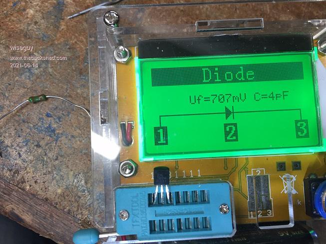 another one gave this better reading: 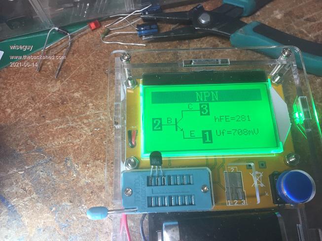 I wired it up as the following schematic with voltages shown, note that C3 & C4 are not wired up yet: 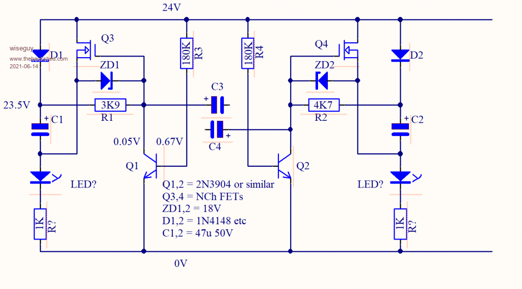 Voltage readings are the same for both sides. When C3 & C4 are connected the LEDs should begin to flash - when its working voltage readings are now useless - they are all in motion/unstable. Final wiring: 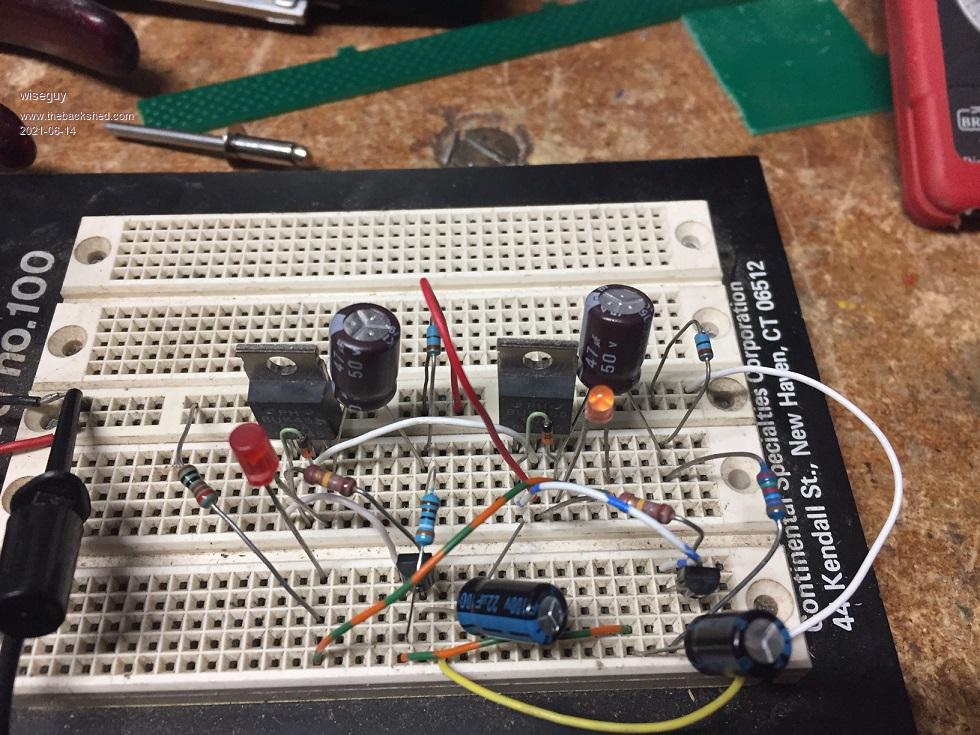 If you havent got a component tester I highly recommend one they are ~12$ from Ali. I recommend be very cautious buying semiconductors from any Ali source I have had lots of counterfit crap sent to me. A few cents saved = a few hours wasted. The component values are not critical to get it working, the 3k9s can be as high as 22K and the 180Ks can be from 100K - 270K Zener can be from 12V to 18V so don't get hung up on copying the schematic exactly. At this point I cant help any further - you need to attack it with a fresh mindset and known good parts. If at first you dont succeed, I suggest you avoid sky diving.... Cheers Mike |
||||
| wiseguy Guru Joined: 21/06/2018 Location: AustraliaPosts: 995 |
Component tester link: https://www.aliexpress.com/item/4000357301057.html?spm=a2g0o.productlist.0.0.742033e3iQOPC6&aem_p4p_detail=202106140141525615624926838730016732013 component tester case link : https://www.aliexpress.com/item/1005001292559487.html?spm=a2g0o.productlist.0.0.1556399dNXeey6&algo_pvid=6442513a-3648-4cbf-bb49-1205949d728b&algo_exp_id=6442513a-3648-4cbf-bb49-1205949d728b-0 Total price including shipping is now closer to $20, shop around it may be cheaper. If at first you dont succeed, I suggest you avoid sky diving.... Cheers Mike |
||||
| Pete Locke Senior Member Joined: 26/06/2013 Location: New ZealandPosts: 179 |
Hello Bob. If you have a basic digital multi meter with a diode test option, it's easy to verify the pin outs of bipolar transistors. Assume it's an NPN transistor as per the circuit. The positive lead of the multi meter will go on the base. You will get slightly different readings when you put the negative lead of the meter on the collector, and then on the emitter. The higher of the two readings is the emitter, and the lower is the collector. It's not a big difference. As an example you may see 0.655 indicated measuring base to collector, and 0.658 indicated measuring base to emitter. Depending on your meter the numbers may be different from the examples, but there is always a difference between the collector and emitter. Chers Pete'. |
||||
| bob.steel Senior Member Joined: 27/02/2020 Location: AustraliaPosts: 188 |
Thanks for that . with some working voltages I should be able to find the fault. The component tester looks handy.I'll get one of those. Thats not much difference at all Pete. Nver looked at them that way . My system is make sure there is a diode reading either side and none when neg on base. The mindset is not the problem . Doing the same thing over and over and expecting a different result is the problem . It leads to madness so you have to jump out of it . Getting working expected voltages at set points gives me a fresh approach . When I start my drill and compressor on the Inverter I use an inrush resistance in series with the line . 5 ohms seems to work well but I use 10 ohms ,2 devices in series on some. Edited 2021-06-14 19:29 by bob.steel |
||||
| wiseguy Guru Joined: 21/06/2018 Location: AustraliaPosts: 995 |
Peter is correct, for ~ 30 years I have tested FETs and Transistors with just a DVM on the diode test function and my tongue for confirming/testing gain....lol. But since buying this tester I have never looked back it gives NCH/PCH, NPN/PNP, gain, pinout and also tests inductors capacitors diodes all in a few seconds. I have found it cuts down my time to identify & assemble something that usually works first time considerably. I used it to confirm the first transistor, but not using it for the second transistor wasted ~ 15 minutes of my time - I assumed (Wrongly!) it was a good one being brand new. Edited 2021-06-14 19:28 by wiseguy If at first you dont succeed, I suggest you avoid sky diving.... Cheers Mike |
||||
| bob.steel Senior Member Joined: 27/02/2020 Location: AustraliaPosts: 188 |
Well with your help I got the transistors worked out . 2 of my new 2955's were shot and the replacements I had were different pinouts so I got new 2955's and checked them and put them in . Now at least the LED's are off . Now to work on the mosfet side and check the voltages . I ordered one of those component checkers too today.How do you check the gain with your tongue though? Edited 2021-06-15 18:37 by bob.steel |
||||
| wiseguy Guru Joined: 21/06/2018 Location: AustraliaPosts: 995 |
I was really hoping no one would ask - but since you did. Actual gain of course remains unknown but can be reliably determined to be bugger all or quite a lot. With the T092 pack, transistors pins 1 & 3, usually E & C are sometimes reversed (or even worse). A transistor still has a bit of gain with C & E reversed but MUCH lower. The resistance of my tongue is typically 50 - 150K. So after using the diode test to determine/confirm which lead is the base I set about determining which pins are the collector and emitter. (lets assume an NPN) I put the neg lead on what I believe is the emitter and the + lead on the collector. Now the fun part, touch the tip of your tongue between the +collector(?) and base. One of 2 things happen: You either feel a slight tingle and not much lowering of the voltage, or you feel almost nothing and get quite a low voltage reading (C&E are correctly identified). If the former reverse the + & - leads and use the tongue trick between the + and base again and it should result in C&E are now correctly identified. I can run the tongue test in a few seconds and it has never let me down - but the new part tester gives me the pinout, VBE, actual gain figure, npn/npn, and feels a tad more professional....... If at first you dont succeed, I suggest you avoid sky diving.... Cheers Mike |
||||
| Warpspeed Guru Joined: 09/08/2007 Location: AustraliaPosts: 4406 |
Sounds a bit tongue in cheek to me. But then what would I know ? Cheers, ĀTony. |
||||
| wiseguy Guru Joined: 21/06/2018 Location: AustraliaPosts: 995 |
 Of course you could use a 100K resistor but juggling 2 meter leads and the part and the resistor was a right pain so I improvised (way back in the days of moving coil meters - Sanwa U50?)....... Of course you could use a 100K resistor but juggling 2 meter leads and the part and the resistor was a right pain so I improvised (way back in the days of moving coil meters - Sanwa U50?).......If at first you dont succeed, I suggest you avoid sky diving.... Cheers Mike |
||||
| Pete Locke Senior Member Joined: 26/06/2013 Location: New ZealandPosts: 179 |
I still have one. Not sure if it still goes, but hopefully I remembered to take the battery out 30 years ago when it went on the 'Might be useful one day' shelf. |
||||
| bob.steel Senior Member Joined: 27/02/2020 Location: AustraliaPosts: 188 |
I am intrigued . The 28volts is on the cmos cchip and the zenner will drop that to 12volts but that wont stop the cmos getting 28 volts. ? I'm assuming the attached pin to the 28v is the voltage in pin and the two devices are channels in the one chip so its max volts in is 18 volts? . Would the zenner not best be placed berore the line into the chip feeding on the voltage over 12 volts passed by the zenner or about 16 volts? Edited 2021-06-16 19:15 by bob.steel |
||||
| wiseguy Guru Joined: 21/06/2018 Location: AustraliaPosts: 995 |
You need to take the whole circuit into consideration. Yes the + supply pin of the IC is tied to 28V but so is the cathode of a 12 V zener. The anode of the zener is tied to the IC's negative supply pin which due to the zener is 12V lower than the 28V supply pin - the Zener wont allow it to be more. The 1K at the bottom has the remaining 16V (of the original 28V) across it. For interest the current through the lower 1K negative connection is 16/1000 or ~16mA. So yes the IC has 28V supplied to the top but with 16V applied to the bottom it only ever sees the zeners 12V across the workings of the IC. The P channel Mosfets need the gate to go a few volts negative relative to the sources - which is tied to 28V. So as the CD4584 chip oscillates between 28V and 12V lower than 28V the gates are driven on with ~ 12V negative pulses with respect to their sources which causes them to switch the 28V on and off to the LEDs. For interest, the bulk of the 16mA available to the cmos IC circuit will just be warming up the zener for 90% of the time as very little current is required for the oscillator or gate switching. If at first you dont succeed, I suggest you avoid sky diving.... Cheers Mike |
||||
| Warpspeed Guru Joined: 09/08/2007 Location: AustraliaPosts: 4406 |
Mike beat me to it. The CD4584 chip just always sees the pretty much fixed 12v across the zener. The supply voltage can drop a fair way below 28v and go a bit higher than 28v, but the zener regulates the supply to the chip. The resistor and capacitor on the first stage causes it to oscillate at a low frequency which may need adjusting. Overall its a very simple circuit with very few parts, and should be very easy to get going. Cheers, ĀTony. |
||||
| bob.steel Senior Member Joined: 27/02/2020 Location: AustraliaPosts: 188 |
Well got it going . Thanks all. I tossed about 4 transistors after trying your tests on them . Had a couple blown ,at least one that gave a very low reading . I have a packet of 100 of them ,2655's so I'll have to go through them. Video proof at Mega Site This is with my actual LED dual lamp wired in as well.Next up that hard soldered board I made up. Tranies were shot so Ill put new in and check the board better. I'm trying to buy that CD4584 chip but have not found a cheap one yet.Ill make that circuit . I think that will control the lamp a bit better as far as one on and one off . The blinks are a bit blurred together on this on as you will see in the vid. Might take it out to 2 seconds on each. 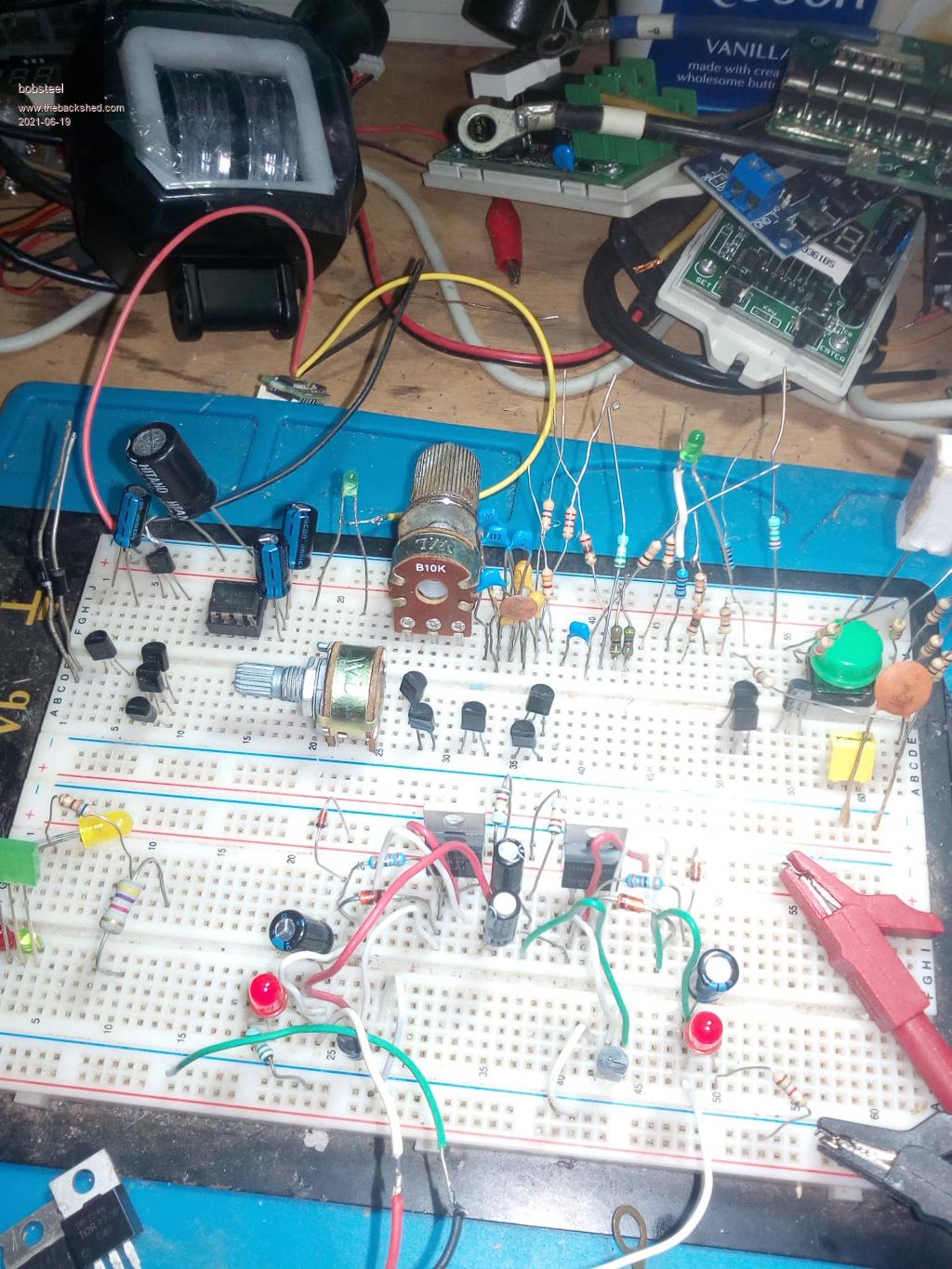 Edited 2021-06-19 20:06 by bob.steel |
||||
| Warpspeed Guru Joined: 09/08/2007 Location: AustraliaPosts: 4406 |
Altronics have a Z4584 for $1.05 Also a Z4093 which is functionally the same for $1.25 Jaycar also have 4093 for $1.65 Cheers, ĀTony. |
||||
| Pete Locke Senior Member Joined: 26/06/2013 Location: New ZealandPosts: 179 |
A CD4069 will also work. Cheers Pete'. |
||||
