
|
|
Forum Index : Microcontroller and PC projects : PicoMite Alpha Firmware
| Author | Message | ||||
Grogster Admin Group Joined: 31/12/2012 Location: New ZealandPosts: 9585 |
I use that tiny little RTC module in most of my projects, and always seems to work fine.  Smoke makes things work. When the smoke gets out, it stops! |
||||
| Volhout Guru Joined: 05/03/2018 Location: NetherlandsPosts: 5027 |
While Peter is having his well deserved rest, playing with the picomite surfaced some things to desired. Maybe this is not the right time, but here is what I desire for my area of interest. #1: in the editor, a larger buffer size (F4/F5 can only copy some 255 characters). Maybe it is possible to enlarge that to 1k ? #2: a "DAQ" command that autonomously captures ADC data with accurate sample rate. I have tried to write such (see my posts about calculating RMS on the MX170) in basic, but fail to get sufficient speed and timing accurate. General requirements: a/ programable sample frequency up to 4kHz b/ minimal 2 ADC's (i.e. measure voltage and current). c/ strict phase (or-time) relation between the 2 ADC's. Sampling simultaneous is best, but if there is X us between them that is also fine. Math can solve that, and for some applications that is not even critical. d/ put the raw ADC data into an integer array X(1,n) where n is the number of samples. nice to have: e/ optional external trigger (i.e GP1). f/ optional running in background #3: Nice to have: can be simple, but can also get as large as you want it. It would be nice to have a "GRAPH" command that can display a set of data in a window on the display. In it's simplest form it scales a single dimension array to the windows size and plots the datapoints using linear interpolation. Things that can be added are line color, axis, ticks, legend, X-Y graph, other graphing forms (histogram), 3d graph. Again, this is nice to have, because it can be done in a page of basic code, and is not time critical. And work arounds (like copying a CSV to excel) exist. Maybe more for CMM2 than pico. Volhout PicomiteVGA PETSCII ROBOTS |
||||
| Mixtel90 Guru Joined: 05/10/2019 Location: United KingdomPosts: 7821 |
I agree on point #1, Volhout. 255 chars can be pretty annoying at times and a bigger buffer would add to the usability of the editor immensely. However, I suspect that it might be using the string handling routines of MMBasic (I think it's the same on the other platforms). In that case we might be stuck with it. Mick Zilog Inside! nascom.info for Nascom & Gemini Preliminary MMBasic docs & my PCB designs |
||||
| Volhout Guru Joined: 05/03/2018 Location: NetherlandsPosts: 5027 |
CMM2 has a larger buffer, so unless CMM2 has a special patch, it should be possible. Volhout PicomiteVGA PETSCII ROBOTS |
||||
| Mixtel90 Guru Joined: 05/10/2019 Location: United KingdomPosts: 7821 |
CMM2 edits directly to the ASCII file on the SD card though. There's no user program in RAM during editing so all the resources are available too. Mick Zilog Inside! nascom.info for Nascom & Gemini Preliminary MMBasic docs & my PCB designs |
||||
| Volhout Guru Joined: 05/03/2018 Location: NetherlandsPosts: 5027 |
@Peter: there is something wrong with MATH FFT Yesterday I tested MATH FFT MAGNITUDE on the pico using a 1024 size array, and reported the output was a spectrum. I however did not fully trust the result, as there where spurious peaks in the spectrum I could not explain. Last night (yes, deep in the night) I tried to reproduce on the CMM2. But the CMM2 gave similar results. I was not sure if it was me, who did not understand FFT, or something wrong with both implementations. I noticed the peaks in the spectrum could be reduced by applying windowing on the input signal, so I experimented with windowing on both pico and CMM2, and bot behaved the same, but different from what I would expect. Here is a picture of the pico result of a windowed (sin^2 window) sine wave and the resulting spectrum. 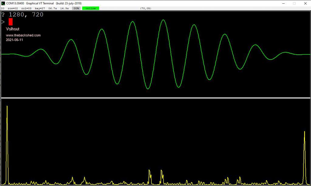 However, if I input the data in excel, and use the analysis toolpack (contains fft) on the same dataset, the result is different, and in line with what I would expect. 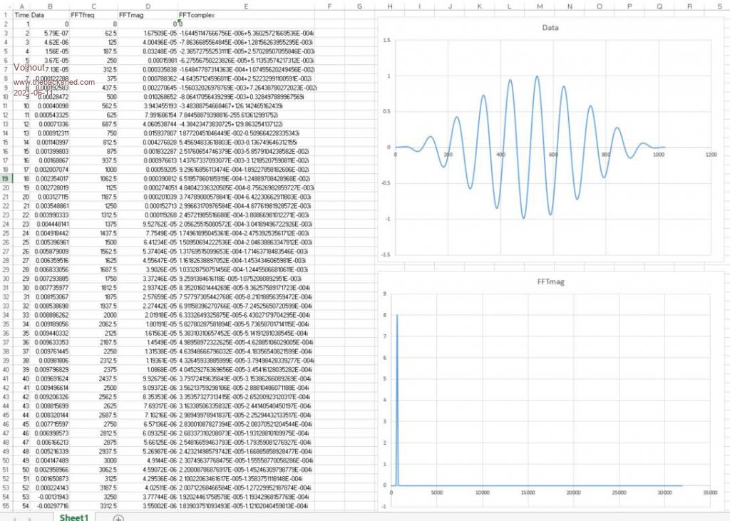 This is a difference I cannot explain. The excel magnitude graph is clean, no spurious. At least not in this linear magnitude view. The only thing I can think of that could explain a bit is that the MMBasic magitude plot is in some kind of logaritmic scale. But even then, the enormous peak at the right side should be visible in the linear view in excel. Note that both plots show 0-511 values of the 0-1023 fft array. Below the test program I used for this test. It is not nice formatted because I was constantly trying to find the bugs in it, and add debug routines. 'GFXterm - magnitude FFT 'init gfxterm parameters Const GFX=Chr$(16) Const ENQ=Chr$(5) Const ACK=Chr$(6) Print GFX "?" Input Gw, Gh Print GFX "clear" 0, 0, Gw, Gh GoSub drw 'defines n=1023 'samples for fft (multiple of 2 - 1) cy = 10 'cycles of sinewave in n samples Dim a!(n),fm!(n),fp!(n) GoSub sinfill 'GoSub sqrfill window=3 '1=trapezoid, 2=triangle, 3=sin^2 GoSub window 'if required 'GoSub sinlist 'End GoSub sinshow Math fft magnitude a!(),fm!() 'GoSub magnitudelog 'Math fft phase a!(),fp!() GoSub fftshow 'GoSub phshow End 'window the input signal to remove spurious window: If window=1 Then For i=0 To n/cy a!(i)=a!(i)*i/(n/cy) a!(n-i)=a!(n-i)*i/(n/cy) Next i ElseIf window =2 Then For i=0 To n/2 a!(i)=a!(i)*i/(n/2) a!(n-i)=a!(n-i)*i/(n/2) Next i ElseIf window=3 Then For i=1 To n a!(i)=a!(i)*Sin(Pi*i/n)*Sin(Pi*i/n) Next i EndIf Return 'show magnitude fft on graphics terminal fftshow: Print GFX "ink" 255, 255, 0, 2 'scan magnitude array mi!=0:ma!=0 'note: the fft array is symetrical, you only need look at first half For i=0 To n/2 mi!=Min(mi!,fm!(i)) ma!=Max(ma!,fm!(i)) Next i 'Print mi!, Ma! ygain=-Gh/(2.2*(ma!-mi!)) yoffset=Gh-ygain*mi! xgain=2*Gw/(n+1) xoffset=0 For i=0 To n/2-1 x1=i*xgain+xoffset x2=(i+1)*xgain+xoffset y1=fm!(i)*ygain+yoffset y2=fm!(i+1)*ygain+yoffset Print GFX "line" x1,y1,x2,y2 Next i Return magnitudelog: Print "magintude log" For i=0 To n fm!(i)=20*Log(fm!(i))/Log(10) Next i Return 'show the phase of the signal phshow: Print GFX "ink" 0, 0, 255, 1 'scan phase array mi!=0:ma!=0 'note: the fft array is symetrical, you only need look at first half For i=0 To n/2 mi!=Min(mi!,fp!(i)) ma!=Max(ma!,fp!(i)) Next i 'Print mi!,ma! ygain=-Gh/(2.2*(ma!-mi!)) yoffset=3*Gh/4 xgain=2*Gw/(n+1) xoffset=0 For i=0 To n/2-1 x1=i*xgain+xoffset x2=(i+1)*xgain+xoffset y1=fp!(i)*ygain+yoffset y2=fp!(i+1)*ygain+yoffset Print GFX "line" x1,y1,x2,y2 Next i Return 'fill input array a() with sine wave samples sinfill: For i=0 To n a!(i)=Sin(i*2*Pi*cy/n) ' a!(i)=a!(i)/2+0.5 'offset ' Print a!(i), Next i Return 'fill input array a() with square wave samples sqrfill: period=Int((n+1)/cy) For i=0 To cy-1 For j=0 To period/2 - 1 a!(i*period+j)=1 Next j For j=period/2 To period a!(i*period+j)=-1 Next j ' Print a!(i), Next i Return 'show the graph of the input signal sinshow: Print GFX "ink" 0, 255, 0, 2 ygain=-Gh/5 yoffset=Gh/4 xgain=Gw/(n+1) xoffset=0 For i=0 To n-1 x1=i*xgain+xoffset x2=(i+1)*xgain+xoffset y1=a!(i)*ygain+yoffset y2=a!(i+1)*ygain+yoffset Print GFX "line" x1,y1,x2,y2 Next i Return sinlist: For i=1 To n Print a!(i) Next i Return 'draw frames drw: Print GFX "ink" 255, 255, 255, 2 Print GFX "line" 0,Gh,0,Gh/2+1 Print GFX "line" 0,Gh,Gw,Gh Print GFX "line" 0,Gh/2+1,Gw,Gh/2+1 Print GFX "line" Gw,Gh,Gw,Gh/2+1 Print GFX "line" 0,0,0,Gh/2-1 Print GFX "line" 0,0,Gw,0 Print GFX "line" 0,Gh/2-1,Gw,Gh/2-1 Print GFX "line" Gw,0,Gw,Gh/2-1 Return PicomiteVGA PETSCII ROBOTS |
||||
| matherp Guru Joined: 11/12/2012 Location: United KingdomPosts: 10189 |
Is the basic FFT correct? |
||||
| Volhout Guru Joined: 05/03/2018 Location: NetherlandsPosts: 5027 |
I just tried running the normal FFT and calculate the magnitude samples from: Magn = sqr(Re^2+Im^2) and get the exact same result. Something fishy in the fft function. But it is the same in the CMM2. If you solve it there, you solve it in pico... Could it be something with the format of the float used ? But if I look at your earlier post for the H7 the FFT graph (magnitude) did not show the high peak at the right of the spectrum (and you also plotted 512 values from the 1024 array). Could it be something that was changed with the H7 -> CMM2 transition. And now pico inherits... Volhout Edited 2021-06-11 23:40 by Volhout PicomiteVGA PETSCII ROBOTS |
||||
| matherp Guru Joined: 11/12/2012 Location: United KingdomPosts: 10189 |
Do you have an H7 to test with, or can anyone else volunteer? Both with the older firmware and the 5.07 beta. |
||||
| Volhout Guru Joined: 05/03/2018 Location: NetherlandsPosts: 5027 |
Peter, I do not have an H7, someone else might be able to double check. This is the CMM2 progam I use to check FFT pressing "a" increases the number of sine waves per 1024 fft samples pressing "z" decreases pressing "w" cycles through some windows (none, triangular, (co)sine (=hann)) 'check fft magnitude function n=1023 'samples cy=10 'cycles dim a!(n),fm!(n) w=0 'window type, 0=none do cls 'draw 2 frames using mm.hres mm.vres box 50,0,(mm.hres-51),mm.vres/2-2 box 50,mm.vres/2,mm.hres-51,mm.vres-1 'prepare input signal sinfill if k$="w" then w=(w+1) mod 4 if w then window 'plot input signal plot_in 'do fft math fft magnitude a!(),fm!() 'plot fft plot_fft 'keyboard commands do k$=inkey$ loop until k$<>"" if k$="a" then cy=cy+1 if k$="z" then cy=cy-1:cy=max(cy,2) loop until k$="q" end 'subroutines 'fill the input array a!() with cy cycles of sinewave sub sinfill for i=0 to n a!(i)=sin(2*pi*cy*i/n) next i end sub 'apply a window over the input signal (triangle for now) sub window if w=1 then for i=0 to n/2 'linear a!(i)=(i/n)*a!(i) a!(n-i)=(i/n)*a!(n-i) next i ? @(60,5) "window linear" else if w=2 then for i=0 to n 'quadratic (do linear twice) a!(i)=(i/n)*a!(i) a!(n-i)=(i/n)*a!(n-i) next i ? @(60,5) "window quadratic" else if w=3 then for i=0 to n 'cosine window a!(i)=(1-cos(2*pi*i/n))*a!(i) next i ? @(60,5) "window cosine" end if end sub 'plot the input signal in the upper window sub plot_in 'find minimum and maximum mi!=0:ma!=0 for i=0 to n mi!=min(mi!,a!(i)) ma!=max(ma!,a!(i)) next i '? mi!,ma! 'calculate gain and offset to fit it into the window xgain=(mm.hres-50)/n xoffs=50 ygain=-(mm.vres/2.3)/(ma!-mi!) yoffs=mm.vres/4-ygain*(ma!+mi!)/2 'plot the actual samples using linear interpolation for i=0 to n-1 line i*xgain+xoffs,a!(i)*ygain+yoffs,(i+1)*xgain+xoffs,a!(i+1)*ygain+yoffs next i 'add legend ? @(mm.hres/2,5) "input linear" ? @(5,5) str$(ma!,2,2) ? @(5,mm.vres/2-20) str$(mi!,2,2) end sub 'plot the fft output in the lower window sub plot_fft 'find min and max and where max is mi!=0:ma!=0 for i=0 to n/2 'fft output is symetrical mi!=min(mi!,fm!(i)) ma!=max(ma!,fm!(i)) if ma!=fm!(i) then cf=i':? cf next i '? mi!,ma! 'calculate scaling to fit the window xgain=2*(mm.hres-50)/n xoffs=50 ygain=-(mm.vres/2.3)/(ma!-mi!) yoffs=mm.vres-20 'plot the fft graph for i=0 to n/2-2 line i*xgain+xoffs,fm!(i)*ygain+yoffs,(i+1)*xgain+xoffs,fm!(i+1)*ygain+yoffs next i 'add legend ? @(mm.hres/2,mm.vres/2+15) "magintude linear" ? @(5,mm.vres/2+5) str$(ma!,2,2) ? @(5,mm.vres-30) str$(mi!,2,2); 'put marker ticks in multiples of centre frequency for i=0 to n/2-2 step cf line i*xgain+xoffs,mm.vres/2,i*xgain+xoffs,mm.vres/2+5 if ((i mod(5*cy)) = 0) then line i*xgain+xoffs,mm.vres/2,i*xgain+xoffs,mm.vres/2+15 end if next i end sub PicomiteVGA PETSCII ROBOTS |
||||
| panky Guru Joined: 02/10/2012 Location: AustraliaPosts: 1114 |
I have full SD card access in a15 however, using a25 as follows gives an error SD card connected to GP2,3,4 and 5 (works fine in a15 with these pins - I can list directory contents OK) >OPTION RESET >UPDATE FIRMWARE - copy a25 to Pico - OK - power cycle >OPTION RESET >OPTION SYSTEM SPI GP2,GP3,GP4 -all good, no error message >OPTION SDCARD GP5 -all good, no error message >FILES Error : SD Card not found > also tried using GP1 as SD card CS but same error Doug. ... almost all of the Maximites, the MicromMites, the MM Extremes, the ArmMites, the PicoMite and loving it! |
||||
| lizby Guru Joined: 17/05/2016 Location: United StatesPosts: 3348 |
Works for me, so there's nothing wrong in theory with your setup: > option list OPTION SDCARD GP5 OPTION SYSTEM SPI GP2,GP3,GP4 > files A:/ 1351 bench.bas 26240 ccpico.bas 201 circles.bas 3164 gameoflife.bas 618 gettime.bas 636 grain.bas 11008 gui.bas 22 hello.bas 35 hello0.bas 1444 mcp23017.bas 817 menu.bas 364 pelican.bas 309 settime.bas 367 speed.bas 4515 ta.bas 4700 tain.txt 3017 taout.txt 0 directories, 17 files PicoMite, Armmite F4, SensorKits, MMBasic Hardware, Games, etc. on fruitoftheshed |
||||
| panky Guru Joined: 02/10/2012 Location: AustraliaPosts: 1114 |
Can't put my finger on what I am doing wrong, particularly as it works fine under a15 and other than updating the firmware to a25 (and doing the reset thing), everything else is the same. Is there any way to read which alpha version is loaded? After the firmware upgrade, I have to close TerraTerm then reset the Pico and restart TerraTerm so I never see the sign-on banner. D. Edit: To explain the last para, everytime I reset or power cycle, I loose the USB connection thus I never auto reconnect like others have indicated happens for them. I am running Win7 pro on an Acer laptop and connect to the Pico direct from USB port (ie. no external hub). I have to close TerraTerm before the reset then restart after the reset/power cycle, and it then comes up online however, the startup banner has passed me by at this stage. Edited 2021-06-12 11:30 by panky ... almost all of the Maximites, the MicromMites, the MM Extremes, the ArmMites, the PicoMite and loving it! |
||||
| panky Guru Joined: 02/10/2012 Location: AustraliaPosts: 1114 |
Anyone else out there driving the Pico from a Win7 Pro machine? If so, can you advise what driver you are using? Doug ... almost all of the Maximites, the MicromMites, the MM Extremes, the ArmMites, the PicoMite and loving it! |
||||
TassyJim Guru Joined: 07/08/2011 Location: AustraliaPosts: 6266 |
https://www.raspberrypi.org/forums/viewtopic.php?f=146&t=300053 Worth a try. Jim VK7JH MMedit |
||||
| led-bloon Senior Member Joined: 21/12/2014 Location: AustraliaPosts: 207 |
No troubles here with a25 and SDCard (with defaults too) When all else fails, try flash_nuke.uf2 and start afresh. Part of the pico-sdk and can post if you haven't got it led Miss you George |
||||
| panky Guru Joined: 02/10/2012 Location: AustraliaPosts: 1114 |
Loaded drivers as per Jim's suggestion above. Reloaded a25 and sdcard is now working although I can not see how that would fix the problem. Note I had reloaded a25 numerous times before and carried out identical configuration without any success till now. I still loose the USB connection on every reset or power cycle so I still never see the sign on banner but at least I have access to the sd card. Thanks for the assist. D. ... almost all of the Maximites, the MicromMites, the MM Extremes, the ArmMites, the PicoMite and loving it! |
||||
| Mixtel90 Guru Joined: 05/10/2019 Location: United KingdomPosts: 7821 |
Have you tried messing with cpuspeed, Doug? It defaults to 125000 from a17, which *should* be fine for all Picos. It can go down to 48000 though. You can see the alpha version in the banner on power-up or by doing a hardware reset by grounding the RUN pin. Mick Zilog Inside! nascom.info for Nascom & Gemini Preliminary MMBasic docs & my PCB designs |
||||
| lizby Guru Joined: 17/05/2016 Location: United StatesPosts: 3348 |
I haven't yet found the magic for TEMPR to read a DS18B20. I think I have it wired right, with a pullup resistor, but with multiple pins attempted, I get like this: ?tempr(27) Error : Invalid configuration > setpin 27,din > ?tempr(27) Error : Pin 27 is in use Same with DOUT. I know that the DS18B20 requires both input and output. How do I get a reading with the picomite? (User error is always a possibility.) PicoMite, Armmite F4, SensorKits, MMBasic Hardware, Games, etc. on fruitoftheshed |
||||
| matherp Guru Joined: 11/12/2012 Location: United KingdomPosts: 10189 |
Sounds like I may have b....ed it. Try the version where I announced it was working. You should not set the pin prior to using TEMPR Edited 2021-06-12 23:00 by matherp |
||||
| The Back Shed's forum code is written, and hosted, in Australia. | © JAQ Software 2025 |
